1
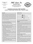
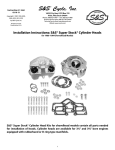
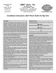
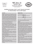
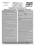
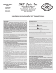
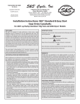
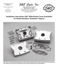
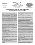
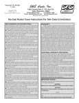
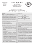
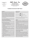
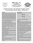
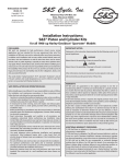
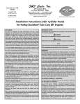
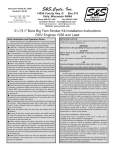
S&S Cycle, Inc.
®
Instruction 51-1114
5-10-06
Copyright © 2002, 2006
by S&S Cycle, Inc.
All rights reserved.
Printed in the U.S.A.
235 Causeway Blvd.
La Crosse, Wisconsin 54603
Phone: 608-627-1497 • Fax: 608-627-1488
Technical Service Phone: 608-627-TECH (8324)
Technical Service Email: [email protected]
Website: www.sscycle.com
Because every industry has a leader
Installation Instructions: 106” S&S® Stroker Kits for
Harley-Davidson® Twin Cam 88® Engines
DISCLAIMER:
IMPORTANT NOTICE:
S&S parts are designed for high performance, off road, racing
applications and are intended for the very experienced rider only. The
installation of S&S parts may void or adversely effect your factory
warranty. In addition such installation and use may violate certain
federal, state, and local laws, rules and ordinances as well as other laws
when used on motor vehicles used on public highways, especially in
states where pollution laws may apply. Always check federal, state, and
local laws before modifying your motorcycle. It is the sole and exclusive
responsibility of the user to determine the suitability of the product for
his or her use, and the user shall assume all legal, personal injury risk and
liability and all other obligations, duties, and risks associated therewith.
Statements in this instruction sheet preceded by the following words
are of special significance.
The words Harley®, Harley-Davidson®, H-D®, Sportster®, Evolution®, and
all H-D part numbers and model designations are used in reference only.
S&S Cycle is not associated with Harley-Davidson, Inc.
SAFE INSTALLATION AND OPERATION RULES:
Before installing your new S&S part it is your responsibility to read and
follow the installation and maintenance procedures in these
instructions and follow the basic rules below for your personal safety.
● Gasoline is extremely flammable and explosive under certain
conditions and toxic when inhaled. Do not smoke. Perform installation
in a well ventilated area away from open flames or sparks.
● If motorcycle has been running, wait until engine and exhaust pipes
have cooled down to avoid getting burned before performing any
installation steps.
● Before performing any installation steps disconnect battery to
eliminate potential sparks and inadvertent engagement of starter while
working on electrical components.
● Read instructions thoroughly and carefully so all procedures are
completely understood before performing any installation steps.
Contact S&S with any questions you may have if any steps are unclear
or any abnormalities occur during installation or operation of
motorcycle with a S&S part on it.
WARNING
Means there is the possibility of injury to yourself or others.
CAUTION
Means there is the possibility of damage to the part or motorcycle.
NOTE
Other information of particular importance has been placed in italic type.
S&S recommends you take special notice of these items.
WARRANTY:
All S&S parts are guaranteed to the original purchaser to be free of
manufacturing defects in materials and workmanship for a period of
twelve (12) months from the date of purchase. Merchandise that fails
to conform to these conditions will be repaired or replaced at S&S’s
option if the parts are returned to us by the purchaser within the 12
month warranty period or within 10 days thereafter.
In the event warranty service is required, the original purchaser must
call or write S&S immediately with the problem. Some problems can be
rectified by a telephone call and need no further course of action.
A part that is suspect of being defective must not be replaced by a
Dealer without prior authorization from S&S. If it is deemed necessary
for S&S to make an evaluation to determine whether the part was
defective, a return authorization number must be obtained from S&S.
The parts must be packaged properly so as to not cause further damage
and be returned prepaid to S&S with a copy of the original invoice of
purchase and a detailed letter outlining the nature of the problem, how
the part was used and the circumstances at the time of failure. If after
an evaluation has been made by S&S and the part was found to be
defective, repair, replacement or refund will be granted.
ADDITIONAL WARRANTY PROVISIONS:
● Consult an appropriate service manual for your motorcycle for correct
disassembly and reassembly procedures for any parts that need to be
removed to facilitate installation.
(1) S&S shall have no obligation in the event an S&S part is modified by
any other person or organization.
● Use good judgement when performing installation and operating
motorcycle. Good judgement begins with a clear head. Don't let
alcohol, drugs or fatigue impair your judgement. Start installation
when you are fresh.
(2) S&S shall have no obligation if an S&S part becomes defective in
whole or in part as a result of improper installation, improper
maintenance, improper use, abnormal operation, or any other misuse
or mistreatment of the S&S part.
● Be sure all federal, state and local laws are obeyed with the
installation.
● For optimum performance and safety and to minimize potential
damage to carb or other components, use all mounting hardware that
is provided and follow all installation instructions.
(3) S&S shall not be liable for any consequential or incidental damages
resulting from the failure of an S&S part, the breach of any warranties,
the failure to deliver, delay in delivery, delivery in non-conforming
condition, or for any other breach of contract or duty between S&S and
a customer.
● Motorcycle exhaust fumes are toxic and poisonous and must not
be inhaled. Run motorcycle in a well ventilated area where fumes
can dissipate.
(4) S&S parts are designed exclusively for use in Harley-Davidson® and
other American v-twin motorcycles. S&S shall have no warranty or
liability obligation if an S&S part is used in any other application.
Introduction
Installation of the S&S® 37⁄8” bore Stroker kit for Harley-Davidson®
Twin Cam 88® engines is relatively straight forward. Assembly
Procedures for the S&S Stroker kit are essentially the same as for
assembly of a stock engine. In addition, a torque plate kit, part
number H-D® #39786, is available from Kent-Moore, through
Harley-Davidson, for fitting the S&S 37⁄8” bore pistons to stock
Twin Cam 88 cylinders.
All reference to Harley-Davidson® part numbers is for
identification purposes only. We in no way are implying that any
of S&S® Cycle’s products are original equipment parts or that they
are equivalent to the corresponding Harley-Davidson® part
number shown.
NOTE- The 106” kit requires stroker flywheels which are included
with the kit. S&S® flywheels for Twin Cam 88® engines are
supplied assembled and balanced. The procedure for installing
an S&S flywheel assembly is the same as for stock flywheels.
Installation Steps
1. Prepare camside crankcase.
2. Check internal engine clearances and assemble crankcases.
3. Final assembly.
4. Engine break-in procedure.
Installation
1. Prepare Camside Crankcase
A.
Refer to appropriate service manual. Remove engine
from frame. Disassemble engine and split crankcases.
B.
Temporarily install cams to be used in camside
crankcase. Refer to S&S cam installation instructions.
Turn cams at least one full rotation, and note any
clearance problems between the cam lobes and the
crankcase. Pay particular attention to pinion bearing
boss and tappet guide boss areas.
C.
Machine material from crankcase to achieve .030”
clearance between cam lobes and crankcase. See
Picture 1 & 2.
Picture 1
CAUTION
Clearance between cam lobes and crankcase must be checked
at pinion bearing boss and tappet guide boss. Machine case
to achieve .030” minimum clearance.
D.
2.
Install piston oiler kit, S&S Part #31-2026. Lubricate oring with engine oil. Apply Loctite® 243 to threads of
machine screws. Install and torque to 25 in-lbs. See
Picture 3.
Check internal engine clearances and assemble crankcases.
Many clearance checks can be made at the same time that
some assembly steps are performed. This can save time for
the engine builder.
A.
Cylinder to piston fitment.
1.
2.
3.
4.
The 106” Stroker 37⁄8” bore pistons, S&S piston series
92-1210, require a clearance of .002”-.0025” to
cylinder bore. S&S recommends that torque plates
be installed on cylinders when boring and honing
to achieve proper fitment tolerance.
Identify front and rear pistons. The rear piston will
have a notch machined into the piston skirt for
clearance with the front piston. This notch must
face the center of the engine, towards the front of
the motorcycle.
Check piston ring gap. Install piston ring into
finished cylinder and square-up ring to bore using
the piston. The required ring gaps are as follows:
Top two compression rings .016” - .022”
Oil control rings (rails) .015” - .035”
File or grind ring ends as necessary to establish
proper end-gap.
Wash finished cylinder in hot, soapy water to
remove honing abrasive from cylinder bore. Rinse
with clean water and apply a light oil to the bore to
prevent rust.
Picture 2
Clearance between cam lobes and crankcase must be checked at pinion bearing boss and tappet guide boss. Grind or machine case
to achieve .030” minimum clearance.
2
Picture 3
CAUTION
Cylinders that have not been cleaned with soap and hot
water will release abrasive into the oil as the engine reaches
operating temperature, resulting in accelerated wear of
internal engine components, greatly reducing engine life.
Picture 4
NOTE - If clearancing is required. Tape off the pinion and cam
bearings to prevent chips from getting into bearings.
D.
Piston to piston clearance.
1.
B. Piston to head clearance,
1.
2.
Install flywheel assembly in right crankcase only.
Assemble pistons without rings on their proper
connecting rods. Installation of wristpin clips is
not necessary.
NOTE - A minimum of .060” clearance is required between
pistons at the closest point.
2.
NOTE - Rear piston has piston to piston clearance notch machined
in piston skirt, place notch toward center of engine.
3.
4.
Install both cylinders and temporarily secure each
with one nut.
Rotate flywheel to position where pistons are at
TDC. Piston deck should be flush with cylinder head
gasket surface.
NOTE - The stroker engine is designed with .045” piston to head
clearance (squish), which is provided by thickness of head gasket.
Therefore, pistons at TDC should be flush with head gasket
surface of cylinders. If pistons are higher than cylinders at TDC,
then something is wrong and S&S® should be notified.
Rotate flywheel to position where pistons are
closest to each other. See Picture 5. Check clearance
between pistons.
E.
If additional clearancing is needed, disassemble
cylinders and pistons and carefully file edge of
piston skirts until clearance is obtained. Clean
all parts.
Piston to piston oiler clearance. This step can be done at
the same time as Step C above.
1.
2.
3.
4.
Rotate flywheel to position where rear piston is at
bottom of travel.
Check clearance between piston skirt and piston
oiler. See picture 6.
Repeat for front piston.
If clearance between piston skirts and piston oilers
is less than .060”, file notch in piston skirt to achieve
required clearance.
CAUTION
Insufficient clearance between piston domes and cylinder
heads will damage pistons, heads and/or other engine
components.
C.
Connecting rod to crankcase clearance.
1.
2.
Rotate flywheel to positions where connecting rods
are closest to crankcase and cylinder spigots in front
and rear. There must be a minimum of .060”
clearance between connecting rods and crankcases
or cylinder spigots. See Picture 4.
Clearance crankcases or cylinder spigots if needed.
Connecting rod to crankcase clearance is usually not
a problem with S&S Stroker kits, but if engines are
built with longer strokes or heavier connecting rods
a potential for contact exists.
Picture 5
3
H.
Check Valve to piston clearance at TDC.
1.
2.
Picture 6
F.
Assemble lower end - final assembly.
1.
2.
Disassemble cylinders and pistons. Remove flywheel
assembly from right crankcase.
Clean all lower end parts for final assembly.
NOTE - Cleaning parts prior to and during assembly and keeping
parts clean after final assembly are imperative to minimize
contaminants that may circulate in oil and shorten engine life.
Many parts can be cleaned with soap and water first. Then,
reclean all internal parts and gasket mating surfaces using high
quality solvent that does not leave any harmful residues.
3.
4.
5.
G.
Install flywheel assembly. Follow factory procedure.
Bolt crankcases together. Use S&S® torque specs for
crankcase bolts. Torque case bolts in two stages to
10 ft-lb. and finally 15 ft-lb. in the sequence shown
in Figure 1.
Assemble gear case components. Follow S&S
instructions if installing S&S gear drive cams. Follow
factory procedures for all other components.
Spread layer of putty into valve pockets in
both pistons.
Assemble cylinder heads and bolt on cylinders with
head gaskets in place. Install rocker covers and
pushrods. Adjust pushrods so the hydraulic piston
in tappet is bottomed in the tappet bore or on the
HL2T washer if used. This insures that tappets can
not bleed down so valve position will be accurate
for clearance check.
NOTE- The earlier Harley-Davidson® Twin Cam 88® lifters, H-D®
part numbers 18538-99 & 99A, require the S&S HL2T kit number
33-5339. Later lifters, H-D® part number 18538-99B, require the
S&S HL2T kit number 33-5338. Both kits are included with the
stroker engine kits, and either kit is installed & adjusted the same
way - remove the retaining clip from the top of the lifter, and
remove the piston assembly and spring from lifter body. Place the
appropriate HL2T travel limiter into the bore of the lifter and
replace removed components in the order that they were
removed. See Picture 7.
All reference to Harley-Davidson part numbers is for
identification purposes only. We in no way are implying that any
of S&S® Cycle’s products are original equipment parts or that they
are equivalent to the corresponding Harley-Davidson part
number shown.
3.
4.
Turn engine over in normal direction of travel two
complete revolutions.
Disassemble engine and check thickness of putty in
valve pockets.
Check valve pocket fit.
1.
2.
3.
4.
5.
6.
7.
Install pistons without piston rings on correct
connecting rods. Install cylinders.
Turn engine over until piston in front cylinder is at
top dead center. Paint area around valve pockets
on pistons with machinist’s blue.
Place valves in cylinder head leaving off springs and
retainers. Place head on cylinder and secure with
one bolt.
Lower valves until they contact piston. Rotate valve,
marking painted area.
Remove head and check points of contact. Valve
should fit in valve pocket machined in piston dome.
If insufficient clearance exists, remove piston and
machine valve pocket until head of valve fits flush.
Repeat procedure for other cylinder head.
Torque In Sequence
Shown In Two Stages.
Stage 1 - 10 ft-lb.
Stage 2 - 15 ft-lb.
9
4
6
2
7
5
8
Figure 1
4
3
1
NOTES:
● S&S® recommends at least .060” clearance around periphery
of valve.
● S&S recommends at least .060” clearance between intake
valve and piston valve pocket recess, and .080” between
exhaust valve and piston valve pocket recess.
● When checking valve to piston clearance pushrods must be
adjusted so the hydraulic piston in tappet is bottomed in the
tappet bore or on the HL2T washer if used. This insures that
tappets can not bleed down so valve position will be
accurate for clearance check.
CAUTION
Insufficient clearance between piston and valves may cause
them to contact each other during operation resulting in
damage to piston and valve train components.
5.
6.
3.
If insufficient clearance exists, machine piston until
proper clearance is achieved.
Disassemble top end and clean all parts for
final assembly.
CAUTION
Manufacturing chips, dirt and/or other contaminants
circulating in engine oil may possibly damage engine
components resulting in shorter engine life and possible
engine failure.
WARNING
● Some solvents, degreasers and other chemicals are harmful to
skin, eyes and other body parts. Many items are flammable
and present a fire hazard. Read manufacturer’s instruction
label for proper use. Use in well ventilated area and wear
protective clothing when using them to avoid personal
injury.
● Compressed air and particles dislodged by compressed air
are harmful to eyes and body. Wear protective goggles
when using compressed air and always direct air stream
away from yourself and other people near you.
A.
Head gasket surface flatness check. Before top end is
assembled, head gasket to cylinder mating surfaces
should be checked.
Final assembly.
NOTE - Cleaning parts prior to and during assembly and keeping
parts clean after final assembly are imperative to minimize
contaminants that may circulate in oil and shorten engine life.
Many parts can be cleaned with soap and water first. Then,
reclean all internal parts and gasket mating surfaces using high
quality solvent that does not leave any harmful residues.
CAUTION
Incomplete contact between gasket surfaces of cylinders and
cylinder heads may cause combustion leakage possibly
resulting in damage to cylinders and/or other engine
components.
1.
Be sure to read and follow manufacturer’s instruction label
before use. Use drill bits and compressed air to clean all oil
passageways of dirt, filings, etc. whenever possible. All iron or
steel parts should be coated with engine oil immediately after
cleaning to prevent rust. During actual final assembly, recoat all
internal parts with high quality engine oil.
2.
3.
33-5339
Thoroughly clean head and cylinder gasket
surfaces.
Place straight edge across head gasket surface at
different places around diameter to determine
flatness.
If unevenness is revealed, machine head gasket
surface just enough to make complete contact.
18539-99A
18539-99B
33-5338
Picture 7
5
CAUTION
Improper torquing sequence and head bolt torque values may
cause head gasket failure.
6.
Bolt heads on cylinders. Follow the stock bolt tightening
sequence, and use stock three stage procedure and
torque values shown in Figure 2. See Figure 2.
IMPORTANT NOTE - Proper first time engine start-up and breakin is critical to achieve permanent and lasting head gasket seal.
Follow “Engine Break-In” procedures at end of section.
CAUTION
Picture 8
B.
Top end assembly procedure.
1.
2.
Thoroughly clean all top end parts and blow dry
with compressed air. Use high grade lacquer
thinner on gasket surfaces.
Apply an assembly lube to the wristpin and wristpin
bushing in the connecting rod. Install pistons on
connecting rods, keeping note of proper placement
and orientation. Install piston rings.
a. Install oil ring support rail in the bottom of
the oil ring groove. See Picture 8.
b.
Install oil ring separator and the oil control
rings.
c.
The plain cast ring is to be installed in the
second ring groove, dot facing up.
d.
The chrome-faced ring is to be installed in the
top ring groove, either side up.
Install wristpin retaining clips.
NOTE - S&S® recommends the use of clip installer, part number
H-D® 42317, available from Kent-Moore, through HarleyDavidson®, or similar tool, for clip installation.
All reference to Harley-Davidson® part numbers is for
identification purposes only. We in no way are implying that any
of S&S® Cycle’s products are original equipment parts or that they
are equivalent to the corresponding Harley-Davidson® part
number shown.
3.
4.
5.
Coat piston skirts with engine oil and install
cylinders.
Install head gaskets dry. Be sure head gaskets are
properly positioned.
Before installing heads spin each head bolt down
on its respective stud to be sure threads are clean
and free of contamination. Place a drop or two of
oil on threads and under head of each head bolt
just prior to final assembly.
NOTE - Light coating of oil on head bolt threads minimizes
friction so torque values will not be distorted. It cannot be
emphasized enough that these steps must be done carefully.
Maintaining a good head gasket seal depends on it.
Improper first time engine start-up and break-in procedure
may cause head gasket failure.
7.
Finish assembling top end per Harley-Davidson® specs.
Install pushrods and adjust.
NOTE - The earlier Harley-Davidson Twin Cam 88® lifters, H-D®
part numbers 18538-99 & 99A, require the S&S HL2T kit number
33-5339. The later lifters, H-D® part number 18538-99B, require
the S&S HL2T kit number 33-5338. Both kits are included with the
Stroker engine kits, and either kit is installed & adjusted the same
way - remove the retaining clip from the top of the lifter, and
remove the piston assembly and spring from lifter body. Place the
appropriate HL2T travel limiter into the bore of the lifter and
replace removed components in the order that they were
removed. To adjust pushrod, rotate engine until the lifter is at its
lowest point, collapse the lifter with the pushrod until it bottoms
against the travel limiter, and then shorten the pushrod one
complete turn (6 flats of the adjuster). Tighten the locknut of the
pushrod adjuster. Repeat for remaining pushrods.
NOTE - If S&S compression releases are to be installed, it is much
easier to install them before rocker covers are installed and the
engine is installed in the frame. S&S die-cast rocker covers for
Harley-Davidson Twin Cam 88 or similar rocker covers with a
center hole must be used if S&S electric compression releases are
to be installed.
Top View
Driveside
2
1
Rear Head
3
4
1
2
Front Head
4
Camside
S&S® Heads or Stock Heads
Stage 1
7 Ft.-Lbs.
Stage 2
14 Ft.-Lbs.
Stage 3
Turn additional 90˚
Figure 2
6
3
8.
Clean oil tank and oil cooler, if applicable, and flush or
replace oil lines before installing engine in frame.
CAUTION
If engine is run with foreign material in the oil tank, engine
damage will occur. Engine damage caused by foreign material
in the oil tank is not covered under the S&S® warranty.
4.
CAUTION
Lugging or running engine prematurely at sustained high rpm
may result in damage to pistons and other engine components.
S&S voids its guarantee if engine is not broken in properly.
G.
For the balance of the first 1000 miles the motor can be
run in a normal but conservative manner. You can be
more liberal with the rpm range and motorcycle can be
operated at normal highway speeds. Avoid overheating
or putting any hard strain on the engine: no drag
racing, dyno runs, excessive speed, trailer towing or
sidecar operation.
H.
After 1000 miles, verify carburetor jetting and
adjustment. Change the engine oil. Motorcycle can now
be operated normally.
I.
Have Fun!
Engine break-in procedure.
NOTE - S&S engines are designed for high performance and as
such are not tolerant of inadequate break-in. Correct break-in
will assure longer engine life and will prevent unnecessary
engine damage. Engine damage caused by improper break-in is
not covered under the S&S warranty.
A.
Initial start up. Run engine approximately one minute at
1250-1750 rpm. DO NOT crack throttle or subject to any
loads during this period as head gaskets are susceptible
to failure at this time. During this time, check to see that
oil pressure is normal, that oil is returning the oil tank,
and that no leaks exist.
B.
Shut off engine and thoroughly check for any leaks or
other problems. Let engine cool to the touch.
C.
After engine has cooled, start up again and allow the
motor to build some heat. Engine should be run no
longer than three to four minutes. When the cylinders
become warm/hot to the touch (approximately 150°)
shut the motor down and let it cool to room temp.
Follow the same cautions as for the initial start-up, and
continue to watch for problems.
D.
Repeat this procedure 3 or 4 times. Each successive time
it should take slightly longer to warm up and you can
increase the temp slightly each time (+10°). You can be
more liberal each time with the rpm, gently vary rpm
continuously from idle up to 2500 rpm in the final cycle.
Don’t be too concerned with final carb settings at this
time because idle speed and mixture cannot be correctly
set until the motor reaches full operating temperature.
The motor should not reach that temperature during
these cycles. Do not allow engine temperature to
become excessive. After the motor has cooled to room
temperature for the final time you are ready to start the
1000 mile engine break-in process.
E.
The first 50 miles are most critical for new rings and
piston break-in. Engine damage is most likely to occur
during this period. Keep heat down by not exceeding
2500 rpm. Avoid lugging the motor, riding in hot
weather or in traffic. Vary the engine speed. Do not lug
the engine. We recommend changing the oil at 50 miles.
F.
The next 500 miles should be spent running engine
no faster than 3500 rpm or 60 mph. Avoid continuous
steady speeds, and do not lug the engine. Vary
engine rpm. We recommend changing the oil again
at 500 miles.
Performance Notes:
● Ignition system - S&S engine kits for Harley-Davidson® Twin
Cam 88®, we recommend that an aftermarket or high
performance ignition module be used. Engines built with
S&S kits have higher than stock compression ratios,
performance cams, and in some cases cylinder heads with
combustion characteristics that are different from stock.
These and other factors effect the ignition requirements of
the engine. Programmable ignition systems allow ignition
maps to be optimized for a specific application, but should
be programmed by a qualified technician. Consult the
ignition manufacturer for recommendations regarding use
of a specific ignition system with large displacement high
compression engines.
● Spark plugs - Use spark plugs and wires that are compatible
with the ignition system. Dual plug installations in S&S Super
Stock® heads are not generally necessary.
● All S&S test engines are run using S&S carburetors. S&S Super
E and G carburetors are recommended for most applications
with the Super G being used more often on larger
displacement, freer breathing engines with higher
compression ratios. Typically, engines equipped with S&S
heads require the same or slightly leaner jetting than those
engines fitted with stock heads. Consult the carburetor
jetting instructions for specific jetting recommendations.
● If another type carburetor is used, it must be made to run
rich enough to operate properly and to prevent engine
damage. If you have a problem with another carburetor, S&S
cannot help you and recommends you call the carb
manufacturer with any questions you may have.
● If the motorcycle is used exclusively on a drag strip where
engine temperatures vary, slightly richer jets may be
necessary for best performance. Larger jets/richer mixtures
will enable one to run a colder engine which is sometimes
desirable. This is best determined by experimentation.
7
Performance notes, continued
● Carburetor jetting and spark plug color - While spark plug
color may be used to help determine carburetor jetting, S&S®
recommends that our instructions be used as primary jetting
guide and that plug color indications be used only as
secondary aid. We have found that different brands of
gasoline, gasoline additives, engine heat (due to ignition
timing), and brands of plugs and heat range used distort
plug color drastically making plug reading difficult for the
average tuner. Also, new plugs usually require a road test of
10 miles or more to properly develop the color which means
that quarter mile tests may not be long enough and hence,
not always a good indication of carb jetting. It is best to use
recommended spark plug type and to consult the spark plug
manufacturer if you have questions.
Exhaust Systems
● Drag pipes - While drag pipes can be used with good results
to achieve top end horsepower, they are generally not
recommended for street applications. Carburetor
adjustment and jetting is generally easier for engines with
muffled exhaust systems.
● Muffler systems: Most stock and many aftermarket exhaust
systems are too restrictive and made exclusively for looks
with little consideration given to performance. A very good,
economical street system consists of the stock header pipes
with the crossover tube and a set of low restriction S&S
mufflers. These mufflers work very well in most situations
and offer an inexpensive alternative to a whole new exhaust
system. Low restriction S&S mufflers and stock header pipes
will typically produce 10 hp more than drag pipes in the
midrange. Since the midrange is where the vast majority of
normal riding occurs, it makes this system ideal for the street.
Gearing
● Gearing depends on the total weight of the machine and
rider, the size of the engine, cam, exhaust system and type of
riding to be done. Most high performance engines, and
particularly those with larger displacements, are capable of
pulling more gear. We suggest you break the engine in with
stock gearing to minimize the load on the engine. After the
engine is broken in, you will have a better feel of its
potential and can change gearing accordingly.
● For those who wish to determine their final drive gear ratio
the formula is as follows:
Engine Revolutions per One Revolution of Rear Wheel=
(Clutch Sprocket*) x (Rear Wheel Sprocket*)
(Motor Sprocket*) x (Transmission Sprocket*)
* Number of teeth on each sprocket.
Compression
● Generally speaking, while engines with higher compression
ratios make more horsepower and perform better, they also
tend to lose that performance edge faster, require more
maintenance, are harder to start, and require better
gasoline. As a rule, we recommend a compression ratio of no
greater than 11:1 for engines used in normal street
operation. A word of caution is in order. Before building an
engine that may be unsuitable for your application, carefully
consider your riding needs, riding style and overall
performance objectives.
Because every industry has a leader
8