1
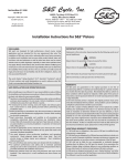
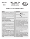
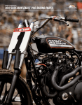
Instruction 510-0087
09-30-13
Copyright © 2013
by S&S® Cycle, Inc.
S&S Cycle, Inc
®
.
14025 Cty Hwy G PO Box 215
Viola, Wisconsin 54664
Phone: 608-627-1497 • Fax: 608-627-1488
All rights reserved.
Printed in the U.S.A.
Technical Service Phone: 608-627-TECH (8324)
Technical Service Email: [email protected]
Website: www.sscycle.com
Installation Instructions:
S&S® Piston and Cylinder Kits
for all 1986-up Harley-Davidson® Sportster® Models
DISCLAIMER:
S&S parts are designed for high performance, closed course, racing
applications and are intended for the very experienced rider only. The
installation of S&S parts may void or adversely affect your factory warranty.
In addition such installation and use may violate certain federal, state, and
local laws, rules and ordinances as well as other laws when used on motor
vehicles used on public highways, especially in states where pollution laws
may apply. Always check federal, state, and local laws before modifying your
motorcycle. It is the sole and exclusive responsibility of the user to determine
the suitability of the product for his or her use, and the user shall assume all
legal, personal injury risk and liability and all other obligations, duties, and
risks associated therewith.
The words Harley®, Harley-Davidson®, H-D®, Sportster®, Evolution®, and all
H-D part numbers and model designations are used in reference only. S&S
Cycle is not associated with Harley-Davidson, Inc.
IMPORTANT NOTICE:
Statements in this instruction sheet preceded by the following words are of
special significance.
WARNING
Means there is the possibility of injury to yourself or others.
CAUTION
Means there is the possibility of damage to the part or motorcycle.
NOTE
Other information of particular importance has been placed in italic type.
S&S recommends you take special notice of these items.
WARRANTY:
SAFE INSTALLATION AND OPERATION RULES:
Before installing your new S&S part it is your responsibility to read and follow
the installation and maintenance procedures in these instructions and
follow the basic rules below for your personal safety.
•• Gasoline is extremely flammable and explosive under certain conditions
and toxic when breathed. Do not smoke. Perform installation in a well
ventilated area away from open flames or sparks.
•• If motorcycle has been running, wait until engine and exhaust pipes
have cooled down to avoid getting burned before performing any
installation steps.
•• Before performing any installation steps disconnect battery to eliminate
potential sparks and inadvertent engagement of starter while working
on electrical components.
•• Read instructions thoroughly and carefully so all procedures are
completely understood before performing any installation steps.
Contact S&S with any questions you may have if any steps are unclear or
any abnormalities occur during installation or operation of motorcycle
with a S&S part on it.
•• Consult an appropriate service manual for your motorcycle for correct
disassembly and reassembly procedures for any parts that need to be
removed to facilitate installation.
•• Use good judgment when performing installation and operating
motorcycle. Good judgment begins with a clear head. Don’t let
alcohol, drugs or fatigue impair your judgment. Start installation when
you are fresh.
•• Be sure all federal, state and local laws are obeyed with the installation.
•• For optimum performance and safety and to minimize potential
damage to carb or other components, use all mounting hardware that is
provided and follow all installation instructions.
•• Motorcycle exhaust fumes are toxic and poisonous and must not be
breathed. Run motorcycle in a well ventilated area where fumes can
dissipate.
All S&S parts are guaranteed to the original purchaser to be free of
manufacturing defects in materials and workmanship for a period of twelve
(12) months from the date of purchase. Merchandise that fails to conform to
these conditions will be repaired or replaced at S&S’s option if the parts are
returned to us by the purchaser within the 12 month warranty period or within
10 days thereafter.
In the event warranty service is required, the original purchaser must call or
write S&S immediately with the problem. Some problems can be rectified by a
telephone call and need no further course of action.
A part that is suspect of being defective must not be replaced by a Dealer
without prior authorization from S&S. If it is deemed necessary for S&S to
make an evaluation to determine whether the part was defective, a return
authorization number must be obtained from S&S. The parts must be packaged
properly so as to not cause further damage and be returned prepaid to S&S
with a copy of the original invoice of purchase and a detailed letter outlining
the nature of the problem, how the part was used and the circumstances at
the time of failure. If after an evaluation has been made by S&S and the part
was found to be defective, repair, replacement or refund will be granted.
ADDITIONAL WARRANTY PROVISIONS:
(1) S&S shall have no obligation in the event an S&S part is modified by any
other person or organization.
(2) S&S shall have no obligation if an S&S part becomes defective in whole or
in part as a result of improper installation, improper maintenance, improper
use, abnormal operation, or any other misuse or mistreatment of the S&S part.
(3) S&S shall not be liable for any consequential or incidental damages
resulting from the failure of an S&S part, the breach of any warranties, the
failure to deliver, delay in delivery, delivery in non-conforming condition, or
for any other breach of contract or duty between S&S and a customer.
(4) S&S parts are designed exclusively for use in Harley-Davidson® and other
American v-twin motorcycles. S&S shall have no warranty or liability obligation
if an S&S part is used in any other application.
1. Remove the cylinder heads, cylinders, and pistons according to
the procedures in the Harley-Davidson® service manual.
2. For 2004-up models – prior to installing the new S&S pistons
and cylinders, move tappet covers as far as possible to toward
the outside of the engine (away from the cylinders) to ensure
adequate clearance between the tappet covers and cylinder
bases.
a. Remove tappet covers from crankcase
b. Clean tappet covers, reusable gaskets, crankcase gasket
surface, and hardware with solvent and a clean rag.
c. Apply blue thread locking compound to tappet cover screws.
d. Reinstall tappet cover gaskets, covers, and screws, but do not
final tighten.
e. Hold the tappet cover as far away from the cylinders as
possible. See Picture 1, below.
f. Torque screws to 120 In*lb in a criss-cross pattern.
Suggested ring end gaps
Ring
Ring Gap Tolerance (inches)
Target Gap
Min
Max
Top
0.016
0.022
0.017
2nd
0.016
0.026
0.021
Oil ring rails
0.010
0.050
0.010 to 0.050
NOTE: Wristpin must be thoroughly cleaned before installation, paying
particular attention to bore. Pass clean, lint-free cloth back and forth
through wristpin bore several times to insure removal of all contaminants.
b. Apply assembly lube to connecting rod bushings, wristpins, and piston wristpin holes.
c. Install pistons with the FWD arrow mark pointing toward the
front of the engine. See Picture 2, below, left.
d. Ensure that wristpin clip groove in piston is free of burrs
and foreign matter. Install wire clips using procedure
recommended in a Harley-Davidson® service manual. End
of clip must rest over notch in piston below wristpin hole to
allow removal of clip in future. Be sure clip is fully seated in
groove.
NOTE: Round “wire” style clips supplied with this kit are identical to and
interchangeable with stock clips in Harley-Davidson® Evolution® engines.
4. Install Piston Rings
NOTE: Ring widths on some piston series may change from time to time.
Part numbers of rings originally supplied with pistons should be recorded
for future reference in the event replacement rings are required.
Picture 1
3. Install S&S Pistons
a. Measure ring end gap by pushing ring about 1 inch into the
cylinder bore from the head end of the cylinder, using the
piston to insert the ring squarely in the bore. See Picture 3,
below. Measure the gap between the ends of the ring with
a feeler gauge. See Picture 4, next page. Compression ring
end gap should be between .016" to .026". Oil ring rail end
gap should be between .010 to .050". If there is insufficient
ring end gap, file the end of the piston ring to achieve the
desired gap. Ends of piston ring must be deburred after filing.
b. Thoroughly clean the piston rings after filing and deburring
and install on pistons.
NOTES:
•These S&S piston scan be used in either the front or rear position.
However, when purchased in a kit with cylinders, each piston must be
kept with the cylinder it was delivered in, as each cylinder is individually
honed to fit a specific piston.
•Rebalancing is not required when installing this kit.
a. Clean pistons and wrist pins with solvent.
Picture 3
Picture 2
2
Incorrect overlap
Incorrect orientation
Correctly butted tips facing up
Figure 1
• Second compression ring gap should be 135° or
approximately 41⁄2" to right of oil expander gap. (See
Figure 5, next page).
• Top compression ring gap should be 135° or approximately
41⁄2" to left of oil expander gap. (See Figure 5 , next page)
CAUTION
Failure to remove burrs from piston ring ends after filing to size,
may cause engine damage. Incorrect installation of rings may
result in poor performance, excessive oil consumption or engine
damage.
Picture 4
c. Install Oil rings (See Figure 4, page 4)
1. Install the oil ring expander in the bottom groove of the
piston. The expander ring has a gold finish. Make sure
the ends of the expander ring are pointed upward and
butted together. Ends must not overlap (See Figure
1, above left). If the tips are overlapped, excessive oil
consumption will occur.
2. Bottom rail gap should be approximately 1.5" or 45° to
right of expander gap.
3. Top rail gap should be approximately 1.5" or 45° to left
of expander gap.
5. Reassemble cylinders, cylinder heads, pushrods, and fuel system
according to procedures in the Harley-Davidson® service manual
or in instructions included with any aftermarket components
used. If high performance cams are installed, valve to piston
clearance must be checked.
NOTE: In all cases it is the engine builder’s responsibility to confirm
proper clearances when assembling an engine. This is especially critical
with performance components such as higher compression pistons and
high lift camshafts. In addition to clearances mentioned, .060" valve-topiston clearance must be confirmed.
NOTE: Confirm that ends of expander do not overlap during installation.
Properly installed expander will appear larger than piston but will
compress when cylinder installed. In some cases, same expander is used
for several bore sizes. Oversize rings will not necessarily have a larger
expander.
d.
CAUTION
Failure to establish proper clearances can result in severe engine
damage not covered under warranty.
6. Engine Break-In Procedure
Install compression rings observing the following:
• Second compression ring is cast iron regular or reverse
torsion type. This ring has a darker, charcoal gray finish.
• Top compression ring may be either moly faced or
chrome faced. This ring has a gray finish that is relatively
light in color.
• Any identifying “pip” marks, dots or oversize marks go to
top of piston.
• If ring has dot and inside diameter bevel, dot goes to top
of piston. See Figure 2, below.
• If ring has no dot but does have inside diameter bevel,
bevel goes to top of piston. See Figure 3, below.
• If ring has no dots and no bevel, it can go either way. See
Figure 4, below.
Figure 2
NOTE: S&S® engine kits are designed for high performance and as such
are not as tolerant of inadequate break-in as a stock engine. Correct
break-in will assure longer engine life and will prevent unnecessary
engine damage. Engine damage caused by improper break-in is not
covered under the S&S warranty.
Figure 3
3
Figure 4
traffic. Vary the engine speed, but do not lug the engine. We
recommend changing the oil at 50 miles.
EXPANDER GAP
TOP RAIL GAP
BOTTOM RAIL GAP
CAUTION
Lugging or running engine prematurely at sustained high rpm
may result in damage to pistons and other engine components.
S&S® voids its guarantee if engine is not broken in properly.
FRONT PISTON
TOP COMPRESSION
RING GAP
f. The next 500 miles should be spent running engine no faster
than 3500 rpm or 60 mph. Avoid continuous steady speeds,
and do not lug the engine. Vary engine rpm. We recommend
changing the oil again at 500 miles.
g.For the balance of the first 1000 miles the motor can be
run in a normal but conservative manner. You can be more
liberal with the rpm range and motorcycle can be operated
at normal highway speeds. Avoid overheating or putting
any hard strain on the engine: no drag racing, dyno runs,
excessive speed, trailer towing or sidecar operation.
h.After 1000 miles, verify carburetor jetting and adjustment.
Change the engine oil. Motorcycle can now be operated
normally.
i. Have Fun!
SECOND COMPRESSION
RING GAP
EXPANDER GAP
TOP RAIL GAP
BOTTOM RAIL GAP
REAR PISTON
TOP COMPRESSION
RING GAP
Additional Information:
The following information is provided in case pistons must be
replaced as in the event of an engine overhaul, or if the engine is
to be set up for immediate severe duty such as drag racing or other
competition application. See Piston Fit Specification chart below.
SECOND COMPRESSION
RING GAP
Figure 5: GAP PLACEMENT ILLUSTRATION
1. For maximum piston and ring life, fit pistons using close fit
dimensions. Close fit requires absolute adherence to new engine
break-in as described in Step 6.
2. For immediate drag strip use, fit pistons using loose fit dimensions.
Break in rings and pistons with 50 easy miles if possible. Piston
and ring life will be reduced with loose fit dimensions.
3. Measure all pistons at widest point across thrust face,
perpendicular to wristpin hole. Several measurements should be
taken to locate widest point. Typically, this will be at bottom of
piston skirt, and approximately 1⁄2" below level of wristpin hole.
4. S&S® recommends #220-#280 grit stone for final honing of S&S
bore cylinders.
5. Follow procedure recommended in Harley-Davidson® service
manual for boring and honing S&S cylinders, or follow instructions
included with S&S Cylinder Torque Plate Kit. Torque plates must
be used to simulate compressive stress in an assembled engine.
Cylinders will distort if torque plates are not used.
a.Initial start up. Run engine approximately one minute at
1250-1750 rpm. DO NOT crack throttle or subject to any loads
during this period as head gaskets are susceptible to failure
at this time. During this time check to see that oil pressure is
normal, that oil is returning to the oil tank, and that no leaks
exist.
b.Shut off engine and thoroughly check for any leaks or other
problems. Let engine cool to the touch
c. After engine has cooled, start up again and allow the motor
to build some heat. Engine should be run no longer than
three to four minutes. When the cylinders become warm/hot
to the touch (approximately 150°) shut the motor down and
let it cool to room temp. Follow the same cautions as for the
initial start-up, and continue to watch for problems.
d.Repeat this procedure 3 or 4 times. Each successive time it
should take slightly longer to warm up and you can increase
the temp slightly each time (+10°). You can be more liberal
each time with the rpm, gently vary rpm continuously from
idle up to 2500 rpm in the final cycle. Don’t be too concerned
with final carb settings at this time because idle speed and
mixture cannot be correctly set until the motor reaches
full operating temperature. The motor should not reach
that temperature during these cycles. Do not allow engine
temperature to become excessive. After the motor has
cooled to room temperature for the final time you are ready
to start the 1000-mile engine break-in process.
e.The first 50 miles are most critical for new rings and piston
break-in. Engine damage is most likely to occur during this
period. Keep heat down by not exceeding 2500 rpm. Avoid
lugging the engine, riding in hot weather, or in stop and go
CAUTION
Failure to follow instructions and perform required clearancing,
installation and/or break-in procedures may result in damage
to pistons and/or other engine components not covered under
warranty.
PISTON FIT SPECIFICATIONS
PART #
DESCRIPTION
CLOSE FIT
LOOSE FIT
106-5548 – STD
106-5549 – +.010"
106-5550 – +.020"
883 TO 1200 CONVERSION PISTON
1986-UP XL 31⁄2" BORE DISHED
DOME
.0025" TO.0030"
0035" TO.0045"
920-0070
1250CC PISTON 1986-UP XL
39/16" BORE FLAT DOME
.0025" TO.0030"
0035" TO.0045"
920-0071
1250CC PISTON 1986-UP XL
39/16" BORE 5.5CC RAISED DOME
.0025" TO.0030"
0035" TO.0045"
*NOTE: FIT WRISTPINS AT .0007" TO .0014".
4