1
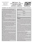
S&S Cycle, Inc.
®
Instruction 51-1025
4-21-06
235 Causeway Blvd.
La Crosse, Wisconsin 54603
Copyright © 1995, 1996,
2002, 2005, 2006
Phone: 608-627-1497 • Fax: 608-627-1488
by S&S Cycle, Inc.
Technical Service Phone: 608-627-TECH (8324)
Technical Service Email: [email protected]
Website: www.sscycle.com
All rights reserved.
Printed in the U.S.A.
Because every industry has a leader
Installation Instructions: S&S® Connecting Rods
DISCLAIMER:
IMPORTANT NOTICE:
S&S parts are designed for high performance, off road, racing
applications and are intended for the very experienced rider only. The
installation of S&S parts may void or adversely effect your factory
warranty. In addition such installation and use may violate certain
federal, state, and local laws, rules and ordinances as well as other laws
when used on motor vehicles used on public highways, especially in
states where pollution laws may apply. Always check federal, state, and
local laws before modifying your motorcycle. It is the sole and exclusive
responsibility of the user to determine the suitability of the product for
his or her use, and the user shall assume all legal, personal injury risk and
liability and all other obligations, duties, and risks associated therewith.
Statements in this instruction sheet preceded by the following words
are of special significance.
The words Harley®, Harley-Davidson®, H-D®, Sportster®, Evolution®, and
all H-D part numbers and model designations are used in reference only.
S&S Cycle is not associated with Harley-Davidson, Inc.
SAFE INSTALLATION AND OPERATION RULES:
Before installing your new S&S part it is your responsibility to read and
follow the installation and maintenance procedures in these
instructions and follow the basic rules below for your personal safety.
● Gasoline is extremely flammable and explosive under certain
conditions and toxic when inhaled. Do not smoke. Perform installation
in a well ventilated area away from open flames or sparks.
● If motorcycle has been running, wait until engine and exhaust pipes
have cooled down to avoid getting burned before performing any
installation steps.
● Before performing any installation steps disconnect battery to
eliminate potential sparks and inadvertent engagement of starter while
working on electrical components.
● Read instructions thoroughly and carefully so all procedures are
completely understood before performing any installation steps.
Contact S&S with any questions you may have if any steps are unclear
or any abnormalities occur during installation or operation of
motorcycle with a S&S part on it.
WARNING
Means there is the possibility of injury to yourself or others.
CAUTION
Means there is the possibility of damage to the part or motorcycle.
NOTE
Other information of particular importance has been placed in italic type.
S&S recommends you take special notice of these items.
WARRANTY:
All S&S parts are guaranteed to the original purchaser to be free of
manufacturing defects in materials and workmanship for a period of
twelve (12) months from the date of purchase. Merchandise that fails
to conform to these conditions will be repaired or replaced at S&S’s
option if the parts are returned to us by the purchaser within the 12
month warranty period or within 10 days thereafter.
In the event warranty service is required, the original purchaser must
call or write S&S immediately with the problem. Some problems can be
rectified by a telephone call and need no further course of action.
A part that is suspect of being defective must not be replaced by a
Dealer without prior authorization from S&S. If it is deemed necessary
for S&S to make an evaluation to determine whether the part was
defective, a return authorization number must be obtained from S&S.
The parts must be packaged properly so as to not cause further damage
and be returned prepaid to S&S with a copy of the original invoice of
purchase and a detailed letter outlining the nature of the problem, how
the part was used and the circumstances at the time of failure. If after
an evaluation has been made by S&S and the part was found to be
defective, repair, replacement or refund will be granted.
● Consult an appropriate service manual for your motorcycle for correct
disassembly and reassembly procedures for any parts that need to be
removed to facilitate installation.
ADDITIONAL WARRANTY PROVISIONS:
● Use good judgement when performing installation and operating
motorcycle. Good judgement begins with a clear head. Don't let
alcohol, drugs or fatigue impair your judgement. Start installation
when you are fresh.
(2) S&S shall have no obligation if an S&S part becomes defective in
whole or in part as a result of improper installation, improper
maintenance, improper use, abnormal operation, or any other misuse
or mistreatment of the S&S part.
● Be sure all federal, state and local laws are obeyed with the
installation.
● For optimum performance and safety and to minimize potential
damage to carb or other components, use all mounting hardware that
is provided and follow all installation instructions.
(3) S&S shall not be liable for any consequential or incidental damages
resulting from the failure of an S&S part, the breach of any warranties,
the failure to deliver, delay in delivery, delivery in non-conforming
condition, or for any other breach of contract or duty between S&S and
a customer.
● Motorcycle exhaust fumes are toxic and poisonous and must not
be inhaled. Run motorcycle in a well ventilated area where fumes
can dissipate.
(4) S&S parts are designed exclusively for use in Harley-Davidson® and
other American v-twin motorcycles. S&S shall have no warranty or
liability obligation if an S&S part is used in any other application.
(1) S&S shall have no obligation in the event an S&S part is modified by
any other person or organization.
S&S® connecting rods are stronger than stock and most other
types of rods because:
1. S&S rods have wider I-beams, heavier radiuses in critical
areas, and extra gusseting.
2.
S&S heavy duty and SUPREME 34-7900 rods are forged from
4140 chrome moly steel. All other SUPREME rods are forged
from 4130EQ chrome moly steel.
3.
S&S rods are heat treated to harder specifications.
4.
S&S rods are shot peened.
IMPORTANT NOTES
● S&S SUPREME rods require additional clearancing in all stock
flywheel assemblies, and stock cases when most stroker kits
are installed. It is the responsibility of the motor builder to
check for any interference in all applications.
● Whenever clearancing is performed during any installation
checks, follow recommended procedures only. Remove
material only from specified areas.
● Thoroughly inspect, debur and clean all parts before
final assembly. Blow air through oil passageways to
check for blockages.
● Read manufacturer's instruction label before using solvents
or degreasers when cleaning and assembling parts.
● Any modification performed to S&S rods other than
those specified in these instructions voids any and all
S&S warranties.
Flywheel and Crankcase Clearancing
Due to increased front to rear I-beam width, crankpin end bulk,
and gusseting of S&S rods, additional rod to flywheel and rod to
crankcase clearancing will be required. Prior to flywheel
rebalancing and final assembly, each flywheel must be mocked
up with mainshaft and rods to check clearances. Places to note
for contact are:
1. Female rod crankpin end to mainshaft nuts - .030" minimum
clearance recommended.
A.
B.
C.
D.
E.
2.
Female rod crankpin end to inner flywheel rim - .060"
clearance recommended.
A.
B.
3.
CAUTION
B.
WARNING
●
●
●
Unwarranted connecting rod clearancing may weaken a
connecting rod possibly causing it to break. A broken
connecting rod may cause the engine to stop suddenly
without warning during operation possibly causing loss of
control of motorcycle and personal injury to you or others.
Some solvents, degreasers, and other chemicals are toxic
and/or harmful to skin and eyes. Many items are
flammable and present a fire hazard. Read manufacturer's
instruction label for proper use. Use in well ventilated area
and wear protective clothing when using them to avoid
personal injury.
Compressed air and particles dislodged by compressed air
are harmful to eyes and body. Wear protective goggles
when using compressed air and always direct air stream
away from body parts such as hands and eyes. Never direct
compressed air toward other people.
Flywheel Balance
All S&S rods, because of their beefier construction, weigh more
than comparable stock types. Therefore, it is recommended to
check and rebalance flywheels when replacing other rods with
S&S types.
4.
While checking female rod to mainshaft clearance,
observe clearance between crankpin end of female rod
and rim of both flywheels.
If additional clearance is required, remove material from
flywheel at point of contact. Do not remove material
from connecting rod.
Wristpin end of both female and male rods to flywheel edge
- .060" minimum clearance recommended.
A.
Failure to follow recommended clearancing procedures and to
use recommended clearances may cause damage to rods
and/or other engine components.
Install sprocket shaft and crankpin in driveside flywheel.
Snug nuts only. Do not torque to final specs.
Slide connecting rods and bearings over crankpin.
Rotate rods on crankpin, and observe clearance
between rod and sprocket shaft nut.
If additional clearance is needed, remove material from
sprocket shaft nut. Do not remove material from
connecting rod.
Repeat procedure for camside flywheel and pinion shaft.
While checking female rod to mainshaft clearance,
observe clearance between wristpin end of both rods
and rim of both flywheels.
If additional clearance is required, remove material from
flywheel at point of contact. Do not remove material
from connecting rod.
Wristpin end to crankcase and cylinder - .060" is
recommended in these areas.
A.
B.
C.
D.
With the camside flywheel and rods mocked up, install
the assembly in the right crankcase half with pistons
(less rings) and cylinders in place.
Rotate flywheel through one full revolution and check
for rod to crankcase and cylinder spigot contact on both
the front and rear of each cylinder.
File or grind crankcase or cylinder spigot as needed to
achieve .060" clearance. Do not remove more material
than needed.
Repeat for left crankcase half.
NOTE: Whenever clearancing is performed in any of these areas,
do not remove any material from the connecting rods as
clearancing on the rods may unnecessarily weaken them. Make
adjustments to the point of contact on the mainshaft nut,
flywheel rim, crankcase, cylinder spigot, etc.
CAUTION
Connecting rods weakened by clearancing may fail causing
serious engine damage.
2
Rod Side Play - Recommended rod side play is .015" to .035". If
on assembly, side play is found to be less than .015", surface
grind equal amounts off thrust faces on both sides of female
rod. The recommended bearing cage width is .008" to .020" less
than the female rod width. This must be checked if female rod
has been narrowed.
Rod to Rod Clearance - S&S® rods have been machined to fit
stroker flywheels up to and including 5" stroke without
additional rod to rod clearance. If a longer stroke is to be used,
this clearance must be checked and increased as necessary - .060"
clearance is recommended and must be removed from the point
of contact on the female rod. Remove only enough material to
obtain recommended clearance. Smooth blend all clearance
contours to avoid stress risers.
Roller Bearing Clearance - S&S rods for street applications have
been honed to .001-.0012" running clearance. These rods require
a new engine break-in period of at least 2000 miles.
NOTE: If connecting rods are to be used in a racing application
where proper engine break-in is not possible, rod bearing races
must be honed to provide a minimum of .0005" additional roller
bearing clearance. S&S can supply rod sets with racing clearance
on request at no additional charge.
SPECIFICATIONS AND RECOMMENDATIONS
Centerline Measurement - All S&S rod sets except 34-7800 and
34-7900 measure 7.440" from wristpin centerline to crankpin
centerline. This dimension is the same as that of stock big twin
rods from 1974 to present and stock Harley-Davidson® Ironhead
Sportster® model rods from 1957 to 1985. This is .030" less than
stock 1936 to 1973 big twin rods. S&S big twin rods can be used
in applications replacing earlier, longer stock rods with the most
noticeable effect being a drop in compression of about 1⁄3 to 1⁄2
point. Piston to piston and piston to flywheel clearances should
be checked.
Rod set 34-7800 measures 6.926" from centerline to centerline.
These rods are the same length as stock 1983 XR-1000® and
1986 and later Sportster® model rods. Rod set 34-7900
measures 7.113" from centerline to centerline and are a special
length
designed
exclusively
for
S&S
four
cam
Sidewinder®/stroker applications.
S&S racing connecting rods utilize a 0.892” diameter wristpin.
Refer to Chart 1 for applications and part numbers. To alter a
bushed S&S rod set to be used with S&S racing pistons which are
equipped with a 0.892” diameter wristpins, the wristpin
bushing must be pressed out, and a 3⁄32” diameter hole drilled on
each side of the I-beam into the pin boss as close to parallel
with the I-beam as possible. See Figure 1. After these holes are
drilled, the wristpin hole of each rod must be honed to provide
0.001” running clearance.
Part #
Application
Rod
Wrist Pin
Bearing
Length Diameter Cage Type
34-7000
1941-'81 bt
7.440"
34-7003
1936-'52 61" bt
7.440"
.791"
Iron
34-7004
1941-'81 bt
7.440"
.791"
Iron
34-7010
34-7011
34-7012
34-7013
34-7200
34-7203
34-7206
34-7210
34-7211
34-7212
34-7213
34-7214
34-7500
34-7510
34-7700
1981-'84 bt
1981-'84 bt
1984-Up bt
1984-Up bt
1941-'81 bt
1941-'81 bt
1941-'81 bt
1981-'84 bt
1981-Up bt
1981-'84 bt
1984-Up bt
1984-Up bt
1957-'81 xl
1981-'85 xl
1957-'81 xl BB
7.440"
7.440"
7.440"
7.440"
7.440"
7.440"
7.440"
7.440"
7.440"
7.440"
7.440"
7.440"
7.440"
7.440"
7.440"
.791"
.791"
.792"
.792"
.791"
.892"
.791"
.791"
.892"
.791"
.792"
.792"
.791"
.791"
.791"
Alloy
Iron
Alloy
Iron
Alloy
Iron
Iron
Alloy
Iron
Iron
Alloy
Iron
Alloy
Alloy
Alloy
34-7703
34-7710
1957-'81 xl BB
1957-'81 xl SB
7.440"
7.440"
.892"
.791"
Alloy
Alloy
34-7720
34-7721
34-7722
34-7730
34-7800
1981-'85 xl BB
1981-'85 xl BB
1986-Up BB
1981-'85 xl SB
1986-Up xl
7.440"
7.440"
7.440"
7.440"
6.926'
.791"
.892"
.792
.791"
.792"
Alloy
Alloy
Alloy
Alloy
Alloy
7.113"
.792"
Alloy
34-7903 1984-Up bt (Spec.) 7.113"
Chart 1
.792"
Alloy
34-7900 1986-Up xl (Spec.)
.791"
Alloy
Wristpin Bushings - Connecting rods for Evolution® engines
are sized for .792" diameter wrist pins. Connecting rods for
pre-1984 engines are sized for .791" diameter wrist pins.
Refer to Chart 1 for part numbers, applications, and wrist pin
diameters. When the correct style wristpin is used a running
clearance is .001".
NOTE: If connecting rods fit for Evolution® wristpins are used
with pre-1984 style wristpins, running clearance will be .002".
Our experience has been that this amount of clearance will not
cause problems, however correct clearance should provide better
engine life and less possibility of noise.
Figure 1
3
NOTE: S&S® offers connecting rod sets which are pre-fit to .892"
diameter wrist pins. S&S also offers .001" and .002" oversize
replacement wristpins for this application. See S&S catalog for
part numbers.
S&S SUPREME Rods for Harley-Davidson® Sportster® modelsThese rods have wristpin ends machined to the same width as big
twin rods (1.073") for 3-5⁄16" or larger bore sizes where more
wristpin support is desired.
NOTE: In applications where less than a 3-5⁄16" bore is used, the
width of the wristpin end is machined to .946”. See the S&S
catalog for part numbers.
CAUTION
Supreme rods with wristpin ends machined to 1.073" width
must not be used in applications where bore size is less than
3-5⁄16" as contact with piston pins boss may result.
Polishing - All S&S rods and are shot peened to increase fatigue
resistance. Grinding and polishing the surfaces reduces this effect
and is not recommended.
Figure 2
Figure 3
CAUTION
●
Do not bend rod by using a tool in wristpin hole as this
method may distort wristpin bushing.
Failure to check and correct rod misalignment can lead to
connecting rod thrusting and potential engine damage.
NOTE: S&S voids its guarantee if any S&S connecting rods are
ground, polished or modified in any way.
●
Crankpin Nuts - All S&S big twin crankpins manufactured after
May 1, 1990 are machined for late 1981 and later style crankpin
nuts. The increased number of threads per inch (1"-20) and the
larger nut surface area provide a stronger crankpin/nut
assembly. Early style stock flywheels may require additional nut
and socket clearance.
Checking Pin Procedure
1. Insert checking pin into wristpin hole. Place strips of paper
between checking pin and crankcase cylinder gasket surface
and apply slight downward pressure to wristpin end of rod
by rotating flywheels. Pull papers out slowly. Drag on
papers should be equal.
2.
NOTE: When this combination is used in some early S&S
flywheels, additional crankpin nut socket to flywheel clearance
may be required. In these instances, S&S recommends removing
the required material from the flywheels before balancing.
Rotate flywheels in opposite direction until checking pin
contacts cylinder gasket surface again. Repeat procedure for
same rod again. If drag on papers is equal no bending is
required. If one paper is loose, use rod bending tool to tweak
rod in direction of loose paper and recheck. See Picture 1.
Torque Specifications - Use green grade Loctite® on the
threads during assembly. Tighten all big twin and Sportster®
model nuts to stock Harley-Davidson® factory specifications in
cast iron flywheels. When using S&S forged flywheels, tighten
big twin nuts to 400 ft. lbs. minimum and Sportster® models to
300-350 ft. lbs..
Preassembly Cleaning - Disassemble and thoroughly clean all
parts in lacquer thinner to remove dirt, filings, etc. Pay particular
attention to the crankpin oil passageways. Reassemble using
high quality break-in grease.
Connecting Rod Alignment
After flywheel assembly has been installed in crankcase, rods
should be checked for alignment. S&S Rod Checking Pin, Part
53-0002, was designed to help perform this procedure. It may
also be necessary to fabricate a rod bending tool as illustrated in
Figure 2. The purpose of this procedure is to compensate for
machining tolerance discrepancies in component parts which
may lead to pistons not running true in cylinder bores. While
the rods are straight and true, it is sometimes necessary to bend
them slightly to compensate for these conditions. Figure 3
shows an exaggerated view.
NOTE: We feel that using a piston in lieu of a checking pin may
prove inaccurate due to variations in lengths of piston skirts from
one side of piston to the other.
4
Picture 1
3.
Repeat checking and bending procedure for other rod.
While disassembling an engine for rebuild or top end work,
observe pistons for wear spots on sides above top compression
ring. If one side near wristpin is worn clean while side opposite
is carboned up, then piston was not running straight and true in
cylinder bore. Piston will also generally show diagonal wear
pattern on thrust faces of skirts and possibly signs of connecting
rod to wristpin boss contact inside piston.
NOTE: We feel that not enough emphasis is given to checking
piston alignment in the cylinder bore. More attention to this
should result in better ring sealing and piston life while promoting
less connecting rod side thrusting and longer rod bearing life.