1
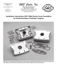
S&S Cycle, Inc.
®
Instruction 51-1052
5-7-06
Copyright © 1999, 2006
by S&S Cycle, Inc.
All rights reserved.
Printed in the U.S.A.
235 Causeway Blvd.
La Crosse, Wisconsin 54603
Phone: 608-627-1497 • Fax: 608-627-1488
Technical Service Phone: 608-627-TECH (8324)
Technical Service Email: [email protected]
Website: www.sscycle.com
Because every industry has a leader
Installation Instructions: S&S® Billet Rocker Covers
for Harley-Davidson® Twin Cam 88®
DISCLAIMER:
IMPORTANT NOTICE:
S&S parts are designed for high performance, off road, racing
applications and are intended for the very experienced rider only. The
installation of S&S parts may void or adversely effect your factory
warranty. In addition such installation and use may violate certain
federal, state, and local laws, rules and ordinances as well as other laws
when used on motor vehicles used on public highways, especially in
states where pollution laws may apply. Always check federal, state, and
local laws before modifying your motorcycle. It is the sole and exclusive
responsibility of the user to determine the suitability of the product for
his or her use, and the user shall assume all legal, personal injury risk and
liability and all other obligations, duties, and risks associated therewith.
Statements in this instruction sheet preceded by the following words
are of special significance.
The words Harley®, Harley-Davidson®, H-D®, Sportster®, Evolution®, and
all H-D part numbers and model designations are used in reference only.
S&S Cycle is not associated with Harley-Davidson, Inc.
SAFE INSTALLATION AND OPERATION RULES:
Before installing your new S&S part it is your responsibility to read and
follow the installation and maintenance procedures in these
instructions and follow the basic rules below for your personal safety.
● Gasoline is extremely flammable and explosive under certain
conditions and toxic when inhaled. Do not smoke. Perform installation
in a well ventilated area away from open flames or sparks.
● If motorcycle has been running, wait until engine and exhaust pipes
have cooled down to avoid getting burned before performing any
installation steps.
● Before performing any installation steps disconnect battery to
eliminate potential sparks and inadvertent engagement of starter while
working on electrical components.
● Read instructions thoroughly and carefully so all procedures are
completely understood before performing any installation steps.
Contact S&S with any questions you may have if any steps are unclear
or any abnormalities occur during installation or operation of
motorcycle with a S&S part on it.
WARNING
Means there is the possibility of injury to yourself or others.
CAUTION
Means there is the possibility of damage to the part or motorcycle.
NOTE
Other information of particular importance has been placed in italic type.
S&S recommends you take special notice of these items.
WARRANTY:
All S&S parts are guaranteed to the original purchaser to be free of
manufacturing defects in materials and workmanship for a period of
twelve (12) months from the date of purchase. Merchandise that fails
to conform to these conditions will be repaired or replaced at S&S’s
option if the parts are returned to us by the purchaser within the 12
month warranty period or within 10 days thereafter.
In the event warranty service is required, the original purchaser must
call or write S&S immediately with the problem. Some problems can be
rectified by a telephone call and need no further course of action.
A part that is suspect of being defective must not be replaced by a
Dealer without prior authorization from S&S. If it is deemed necessary
for S&S to make an evaluation to determine whether the part was
defective, a return authorization number must be obtained from S&S.
The parts must be packaged properly so as to not cause further damage
and be returned prepaid to S&S with a copy of the original invoice of
purchase and a detailed letter outlining the nature of the problem, how
the part was used and the circumstances at the time of failure. If after
an evaluation has been made by S&S and the part was found to be
defective, repair, replacement or refund will be granted.
ADDITIONAL WARRANTY PROVISIONS:
● Consult an appropriate service manual for your motorcycle for correct
disassembly and reassembly procedures for any parts that need to be
removed to facilitate installation.
(1) S&S shall have no obligation in the event an S&S part is modified by
any other person or organization.
● Use good judgement when performing installation and operating
motorcycle. Good judgement begins with a clear head. Don't let
alcohol, drugs or fatigue impair your judgement. Start installation
when you are fresh.
(2) S&S shall have no obligation if an S&S part becomes defective in
whole or in part as a result of improper installation, improper
maintenance, improper use, abnormal operation, or any other misuse
or mistreatment of the S&S part.
● Be sure all federal, state and local laws are obeyed with the
installation.
● For optimum performance and safety and to minimize potential
damage to carb or other components, use all mounting hardware that
is provided and follow all installation instructions.
(3) S&S shall not be liable for any consequential or incidental damages
resulting from the failure of an S&S part, the breach of any warranties,
the failure to deliver, delay in delivery, delivery in non-conforming
condition, or for any other breach of contract or duty between S&S and
a customer.
● Motorcycle exhaust fumes are toxic and poisonous and must not
be inhaled. Run motorcycle in a well ventilated area where fumes
can dissipate.
(4) S&S parts are designed exclusively for use in Harley-Davidson® and
other American v-twin motorcycles. S&S shall have no warranty or
liability obligation if an S&S part is used in any other application.
Kit Contents:
Base, rocker cover, S&S
Chrome billet (2 each) . . . . . . . . . . . . . . . . . . . . . . . .#90-4068
Polished billet (2 each) . . . . . . . . . . . . . . . . . . . . . . .#90-4074
Plain Billet (2 each) . . . . . . . . . . . . . . . . . . . . . . . . . .#90-4066
®
Cover, top rocker, S&S
Chrome billet (2 each) . . . . . . . . . . . . . . . . . . . . . . . .#90-4069
Polished billet (2 each) . . . . . . . . . . . . . . . . . . . . . . .#90-4076
Plain billet (2 each) . . . . . . . . . . . . . . . . . . . . . . . . . .#90-4067
Capscrew, socket head, 1⁄4-20 x 3⁄4”
(12 each, H-D® #4069A) . . . . . . . . . . . . . . . . . . . . . . .#50-0067
Capscrew, socket head w/flat washer
5
⁄16-18 x 3⁄4” (12 each) . . . . . . . . . . . . . . . . . . . . . . . . .#50-0099
Washer, flat 1⁄4” x 7⁄16” x 1⁄16” (12 each)
H-D® #6099 . . . . . . . . . . . . . . . . . . . . . . . . . . . . . . . . .#50-7017
NOTES
● Threads should be cleaned with Loctite® primer or equivalent
prior to applying Loctite®.
● It remains engine builder’s responsibility to check operating
clearances. Clearances should be checked between valve
spring/collar and rocker housing base as well as between
rocker arm and top rocker cover. S&S recommends
minimum of .060” between rocker arm and top collar. A
distance of .025” is sufficient between valve spring/top
collar and rocker housing base. Cylinder head must also be
set up for correct lift.
CAUTION
●
●
Gasket set, rocker cover billet (1 each) . . . . . . . . . . . . . .#90-4073
Failure to establish correct operating clearances can result in
extensive engine damage not covered under warranty.
It is installer’s responsibility to use Loctite® and tighten fasteners
to correct torque values. Failure to install fastener correctly may
result in fastener vibrating loose and causing extensive engine
damage not covered under warranty.
Loctite® 243, 0.5ml. tube (1 each) . . . . . . . . . . . . . . . . . .#51-9003
WARNING
NOTE: All reference to Harley-Davidson® part numbers is for
identification purposes only. We in no way are implying that any
of S&S® Cycle’s products are original equipment parts or that they
are equivalent to the corresponding Harley-Davidson part
number shown.
Sparks from motorcycle electrical system can ignite gasoline fumes.
To prevent sparks as well as prevent electric starter from becoming
engaged inadvertently and causing personal injury, disconnect
battery and remove from motorcycle before proceeding.
1.
Introduction
S&S rocker covers for Harley-Davidson Twin Cam 88® engines
utilize original Harley-Davidson rocker arm support plates and
breather assemblies. Otherwise this kit includes all hardware and
gaskets required for installation.
S&S rocker covers can be installed with engine in frame. S&S
Rocker Cover Wrench Set #53-0040 is helpful in areas where
motorcycle frame prevents use of conventional tools. S&S
strongly recommends use of torque wrench and Loctite® 243 (S&S
#51-9003, included in kit) on all fasteners.
S&S also recommends the installer become familiar with Twin
Cam 88® “Top End Overhaul Procedure” section in HarleyDavidson® Service Manual before beginning installation. Refer
to Harley-Davidson® Service Manual for additional information
as needed. S&S rocker covers are designed to accept valve springs
up to 1.660” O.D. with no modification. In most instances, they
will accept valve lifts to .710” without modification.
Picture 1
2
Wash motorcycle, taking care to remove dirt from engine
and surrounding area of motorcycle. Remove gas tank and
clean engine and surrounding area with compressed air.
CAUTION
Dirt and other contaminants can cause extensive damage if
allowed to fall into engine.
WARNING
High pressure air is potentially hazardous. Wear eye protection
during use and direct air stream away from face and others nearby.
2.
3.
Picture 2
Remove stock top rocker covers. Remove pushrod cover
retainers from front cylinder pushrods and collapse
pushrod covers.
Remove spark plugs, place motorcycle in gear, and rotate
engine to place intake and exhaust pushrods for front
cylinder at lowest point on cam. Confirm that both pushrods
can be rotated with light finger pressure. See Picture 1.
Picture 3
Driveside
Driveside
4
1
Camside
Figure 1
Figure 2
Loosen bolts in sequence and in 1⁄4-turn increments for first 3⁄4 turn.
Bolts can then be removed according to normal procedure.
7.
Remove breather cover and baffle assembly. See Picture 2.
Remove rocker arm/rocker support plate. See Picture 3.
NOTE - Gradually loosen rocker arm support bolts in following
sequence (See Figure 1):
Left (driveside) rear
Right (camside) front
Right (camside) rear
Left (driveside) front
Remove lower rocker housing and gasket from head.
Remove oil and any remaining gasket material from
cylinder head gasket surface and clean gasket surface with
lacquer thinner.
WARNING
Lacquer thinner is extremely flammable, potentially explosive,
and the fumes toxic when inhaled. Read manufacturer’s cautions
on container and use only in a well-ventilated area away from
sparks and open flame.
8.
Loosen bolts in sequence and in 1⁄4-turn increments for first 3⁄4 turn.
Bolts can then be removed according to normal procedure.
6.
5
Camside
Failure to confirm pushrod/lifter placement before proceeding
with installation can result in damage to rocker arm support
plates and other parts. With pushrods at lowest point, front
piston will be at TDC on Compression stroke.
1.
2.
3.
4.
6
2
CAUTION
4.
5.
3
Front
3
Front
4
1
2
Place S&S® lower rocker housing gasket on cylinder head.
Gasket must cover breather channel in cylinder head.
NOTE - It is possible to install gasket incorrectly. Before
proceeding, confirm that gasket is correctly placed and covers
breather channel in cylinder head. See Pictures 4A and 4B.
Remove lower rocker housing bolts.
Prepare threads of six 5⁄16-18 x 3⁄4 S&S rocker housing screws
according to Loctite® instructions and apply Loctite® 243
supplied with kit.
10. Install screws in front and rear driveside holes of lower
rocker housing and install housing on cylinder head.
Screws will hold gasket in correct position as remaining
screws are installed.
11. Install four remaining lower rocker housing screws and
gradually tighten to 15-18 ft-lbs. using sequence described in
Step 6. Measure clearance between valve spring and rocker
cover with feeler gauge. Minimum is .025”. See Picture 5.
9.
NOTE - Gradually loosen lower rocker housing bolts in following
sequence (See Figure 2):
1.
2.
3.
4.
5.
6.
Right (camside) front
Left (driveside) rear
Left (driveside) front
Right (camside) rear
Center front
Center rear
Correct
Picture 4A
Incorrect
Picture 4B
Check clearances
indicated by arrows
in
areas
Picture 5
3
12. Place stock rocker support plate assembly in rocker arm
housing. Prepare stock bolts for Loctite® according to
manufacturer’s instructions and apply Loctite® to threads.
Insert two short rocker support plate bolts in holes in left
(driveside) of plate and two long support plate bolts in
right (camside) holes. Gradually tighten support plate bolts
to 15-18 ft-lbs. according to sequence described in Step 5.
NOTE - Hydraulic lifters may require a few minutes to bleed
down after rocker assembly is installed. Do not rotate engine
until pushrods can be turned with light finger pressure.
13. Prepare breather cover/baffle assembly bolts for Loctite® and
apply Loctite® according to manufacturer’s instructions.
14. Separate top and bottom halves of breather cover/baffle
assembly, clean gasket surfaces, and install center gasket
supplied with S&S® rocker housing kit. See Picture 6. Place
other gasket supplied with kit on lower rocker housing and
install breather cover and baffle assembly. See Picture 7.
Tighten bolts evenly to 90-120 in-lbs.
15. Confirm clearance between rocker arm and top rocker cover
by applying layer of clay at least .060” thick inside areas of
cover that will come closest to rocker arm at maximum lift.
Temporarily install cover with four screws and rotate engine
through two complete revolutions. Remove cover and
examine clay. Layer of clay above rocker arm must remain at
least .060” thick. If dented, indentation must leave at least
.060” of clay between rocker arm and cover. Remove all
traces of clay and thoroughly clean rocker and cover with
clean, lint-free cloth.
16. Install one flat and one fiber washer on each of six 5⁄16-18 x 3⁄4
rocker cover screws.
NOTE - Install flat washer on screw first. Fiber washer goes
between flat washer and rocker cover.
Prepare rocker cover screws for Loctite® and apply Loctite® to
threads. Install rocker cover and gradually tighten screws to 9-12
ft-lbs. in following sequence (See Picture 8):
Right (camside) front
1.
2.
3.
4.
5.
Left (driveside) rear
Left (driveside) front
Right (camside) rear
Left (driveside) center
Right (camside) center
17. Extend pushrod covers and replace retainer clips.
18. Remove covers from rear cylinder pushrods. Rotate engine
to place pushrods at lowest point on cam with rear piston at
TDC. Repeat procedure described above.
19. Replace parts removed for installation, start motorcycle and
inspect for gas and oil leaks.
Gasket
Picture 6
4
Picture 7
Picture 8