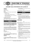
1
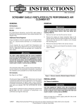
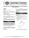
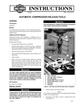
-J04779
REV. 2011-06-06
SCREAMIN' EAGLE PRO STAGE II PERFORMANCE KIT
Prepare the Motorcycle for Service
GENERAL
Kit Number
30076-09
Models
This kit is designed to fit 2008 and later V-Rod model motorcycles.
NOTE
The kit is intended for High Performance applications only.
Engine related performance parts are intended for the experienced rider only.
Additional Parts Required
To prevent accidental vehicle start-up, which could cause
death or serious injury, remove main fuse before proceeding. (00251b)
1.
Remove the right side cover and the main fuse.
2.
Follow service manual instructions to remove the airbox
assembly.
3.
Disconnect the battery, negative (-) cable first.
INSTALLATION
NOTES
Valve shims; see a Harley-Davidson dealer for selection:
Shims 1.825mm through 3.000mm, available from a HarleyDavidson dealer.
The cam removal and installation procedure does not require
the removal of the engine from the frame.
Shims larger than 3.000mm available from sources like
www.hotcamsinc.com
Follow the service manual valve lash procedures in the VRSC
service manual.
SuperTuner recalibration for the ECM. See a Harley-Davidson
Dealer for your model year.
Valve lash specifications will be found in the engine specifications section.
Each service manual or supplement procedure will require
special tools. These tools are called out in the service manual
or supplement and are available through the SPX Kent-Moore
Special Service Tools catalog.
1.
The rider's safety depends upon the correct installation
of this kit. Use the appropriate service manual procedures.
If the procedure is not within your capabilities or you do
not have the correct tools, have a Harley-Davidson dealer
perform the installation. Improper installation of this kit
could result in death or serious injury. (00333a)
NOTE
This instruction sheet references service manual information.
A service manual for your model motorcycle is required for this
installation and is available from a Harley-Davidson Dealer.
Rotate engine toward front cylinder only. Do not rotate
engine toward rear cylinder, as engine damage can result.
(00409c)
2.
Remove the cams per the service manual procedure for
adjusting the valve lash.
3.
Install the new cams and check valve lash per service
manual procedure.
4.
Complete assembly per valve lash procedure.
5.
Follow service manual procedure to time the cams to the
cam drive.
6.
Follow service manual procedures to verify the valve lash.
7.
If required, use a copy of the Valve Lash Calculation
Worksheet found in the Appendix of the service manual.
Adjust the valve lash following service manual MAINTENANCE: VALVE LASH, Verify Cam Timing, and Lash
Adjustment.
8.
After verifying lash adjustment, install and tighten spark
plugs to 17 ft-lbs (23 Nm).
You must recalibrate the ECM when installing this kit.
Failure to properly recalibrate the ECM can result in severe
engine damage. (00399b)
ECM recalibration is required using a SuperTuner. Motorcycle
must not be started until the recalibration is done. See a HarleyDavidson dealer.
Follow the service manual valve lash procedure to reposition the engine in the chassis.
Kit Contents
See Figure 1 and Table 1.
-J04779
1 of 2
Optional Airbox Modifications
1.
Using service manual instructions, remove the airbox
assembly. After removing the intake air temperature sensor
(IAT) and grommet, discard the airbox top cover.
2.
Using the right, left and front side airbox templates (see
last page for templates), lay a template in place and prickpunch the center of the crosshairs. Use a 1 inch hole saw
to drill the larger holes and a 17/32 inch drill bit for the IAT
hole.
3.
Clean lower airbox and install the airbox assembly, velocity
stacks, air filter and cover according to service manual
instructions.
4.
Install IAT grommet and IAT to the airbox and connect the
IAT harness.
SERVICE PARTS
is06246a
B
3
5
4
Return the Motorcycle to Service
1.
Install the main fuse and the right side cover.
2.
Reconnect the battery, positive (+) cable first.
A
NOTE
Calibration can be supplied through any authorized HarleyDavidson dealer.
3.
Before starting the engine, recalibrate the ECM.
2
1
When closing the seat, make sure the ignition switch is in
the FUEL position. If the ignition switch is in any other
position when the seat is closed, the seat latch mechanism
could be damaged. (00196a)
4.
1
2
Close the seat.
7
After installing seat, pull upward on seat to be sure it is
locked in position. While riding, a loose seat can shift
causing loss of control, which could result in death or
serious injury. (00070b)
Test Run Motorcycle
1.
Test start engine. If the oil pressure indicator lamp illuminates, follow the service manual procedure to troubleshoot
the problem.
2.
If there is a rattle heard during engine start-up, follow
service manual procedure to adjust the secondary cam
chain.
Figure 1. Service Parts: VRSC STAGE II PERFORMANCE
KIT
Table 1. Service Parts
Item
Description (Quantity)
Part Number
1
Camshaft assembly, intake (2)
17470-09
2
Camshaft assembly, exhaust (2) 17473-09
3
Air filter element
29793-02C
4
Front velocity stack
30078-09
5
Rear velocity stack
30079-09
6
Cam cover gasket kit (not
shown)
17010-01K
7
Lower airbox drill templates (3) Not Sold Separately
Items mentioned in text, but not included in kit.
-J04779
A
Lower airbox shown with template holes drilled
B
Air filter element cover
2 of 2