1
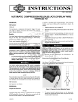
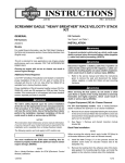
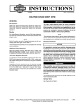
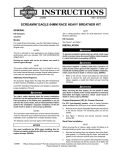
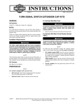
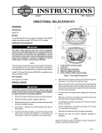
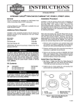
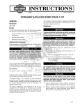
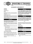
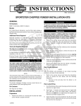
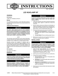
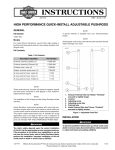
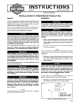
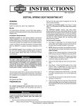
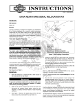
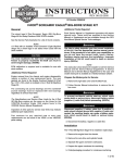
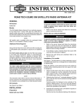
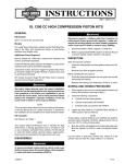
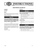
-J03993
REV. 2006-07-27
EFI RACE FUELER
GENERAL
Kit Number
Disconnect negative (-) battery cable first. If positive (+)
cable should contact ground with negative (-) cable connected, the resulting sparks can cause a battery explosion,
which could result in death or serious injury. (00049a)
32136-05A, 32136-06A, and 32136-07
Models
These kits fit the following models:
2.
Table 1. Models
Kits
VRSC models: Remove right side cover and maxi-fuse.
Refer to MAXI-FUSE in Service Manual.
Models
32136-05A
2001-2005 Twin Cam;
2003-2006 VRSC
equipped with EFI
32136-06A
2006 EFI Models
32136-07
2007 XL 1200 and XL
883 equipped with EFI
Softail and Dyna models: Disconnect battery cables,
negative (-) cable first.
XL models: Remove left side cover and maxi-fuse. Refer
to Maxi-Fuse in Service Manual.
Install Race Fueler Box on All EFI Models
When servicing the fuel system, do not smoke or allow
open flame or sparks in the vicinity. Gasoline is extremely
flammable and highly explosive, which could result in
death or serious injury. (00330a)
The rider's safety depends upon the correct installation
of this kit. Use the appropriate service manual procedures.
If the procedure is not within your capabilities or you do
not have the correct tools, have a Harley-Davidson dealer
perform the installation. Improper installation of this kit
could result in death or serious injury. (00333a)
1.
Loosen the fuel tank mounts and rotate tank forward to
gain access to the fuel injector connectors located on the
induction module.
is01107
1
NOTE
This instruction sheet references Service Manual information.
A Service Manual for your model motorcycle is required for
this installation and is available from a Harley-Davidson dealer.
There are no Service Parts available with this kit.
INSTALLATION
Prepare Motorcycle
1.
Softail and Dyna models: Remove seat according to the
instructions in the Service Manual.
1. Wire form
VRSC models: Open the seat.
Figure 1. Connector With Wire Form
2.
To prevent accidental vehicle start-up, which could cause
death or serious injury, disconnect battery cables (negative
(-) cable first) before proceeding. (00307a)
-J03993
Remove fuel injector connector:
a.
See Figure 1. Kit 32136-05A, press wire form to
remove connector.
b.
See Figure 2. Kit 32136-06A, press gray release tab
to remove connector.
c.
See Figure 3. Kit 32136-07, press release tabs to
remove connector.
1 of 5
is01109
is03550
1
2
3
1
1. Male connector
2. Release tab
Figure 2. Connector With One Release Tab
is03551
2
1
2
1. Race fueler box
2. Hook and loop strip
3. Black wire to ground
2
Figure 4. Racer Fueler Box (Typical)
1. Male connector
2. Release tab (2)
6.
Attach black wire (3) on EFI race fueler box to ground.
7.
See Figure 5. Connect male yellow/white lead (1) on fueler
box to yellow/green and white/yellow injector wires (2).
8.
Connect female yellow/white lead (3) on fueler box to front
cylinder injector.
9.
Connect male green/yellow lead (4) on fueler box to
yellow/green and green/grey injector wires (5).
Figure 3. Connector With Two Release Tabs
3.
4.
5.
See Figure 4. Determine best location for mounting race
fueler box (1). The location will vary depending on motorcycle model. The race fueler box must be mounted with
the wires facing down. The connections from the race
fueler box will connect to each fuel injector and harness.
Determine best routing for the race fueler box wires
between the induction module and mounting location. This
will vary depending on motorcycle model.
Attach hook and loop strip (2) to back of race fueler box
and attach box with wires down to desired location (near
fuse box or in front of battery, etc.). Do not mount to battery.
NOTE
Connect black (gnd) lead to ground only. If black lead is connected to positive side of battery, the EFI race fueler box will
fail.
10. Connect female yellow/green lead (6) on fueler box to rear
cylinder injector.
11. Keep wires out of the way of hot or moving parts with cable
ties provided in kit.
Connect positive (+) battery cable first. If positive (+) cable
should contact ground with negative (-) cable connected,
the resulting sparks can cause a battery explosion, which
could result in death or serious injury. (00068a)
12. Connect battery cables, positive (+) cable first.
13. Verify initial power-up and monitor mode and make initial
RPM threshold, fuel adjuster and accelerator enrichment
settings. See "Tune Race Fueler Box" topic.
14. Return fuel tank to its original position and tighten fuel tank
mounts to specification.
-J03993
2 of 5
is01211
2
3
1
7
5
4
6
8
1. Male connector, front cylinder
2. Wiring harness, front connector (grey/yellow/white
wire)
3. Female connector, front cylinder
4. Female connector, rear cylinder
5. Wiring harness, rear connector (light
green/yellow/dark green wire)
6. Male connector, rear cylinder
7. Battery ground (Do not attach to positive terminal)
8. Delphi injector body
Figure 5. Race Fueler Box Connections (Typical)
Install Race Fueler Box on VRSC Models
1.
Remove airbox cover following the instructions in the
Service Manual.
2.
Remove front side covers to gain access to wiring.
Remove horn to access fuel injector.
is01213
1
2
1. Race fueler box
2. Wires at the bottom
Figure 6. Fueler Box Wire Location
3.
-J03993
Route race fueler box wires from injector connectors to
front of vehicle by inserting wires under air box.
3 of 5
4.
See Figure 6. Mount race fueler box (1) with wires facing
down (2) in most accessible location using hook and loop
strip.
NOTE
Connect black (gnd) lead to ground only. If black lead is connected to positive side of battery, the EFI race fueler box will
fail.
5.
See Figure 5. Connect male yellow/white lead (1) on fueler
box to yellow/green and white/yellow injector wires (2).
6.
Connect female yellow/white lead (3) on fueler box to front
cylinder injector.
7.
Connect male green/yellow lead (4) on fueler box to
yellow/green and green/grey injector wires (5).
8.
Connect female yellow/green lead (6) on fueler box to rear
cylinder injector.
9.
Keep wires out of the way of hot or moving parts with cable
ties provided in kit.
10. Install maxi-fuse and right side cover. Refer to MAXI-FUSE
in Service Manual.
11. Verify initial power-up and monitor mode and make initial
RPM threshold, fuel adjuster and accelerator enrichment
settings. See "Tune Race Fueler Box" topic.
12. Install airbox cover following the instructions of the Service
Manual.
TUNE RACE FUELER BOX
the race fueler box has power and that all three LEDs are
operating.
2.
The race fueler box will then enter the monitor mode,
waiting for the engine to start running. During monitor
mode, the center (yellow) LED will flash about twice per
second.
3.
When the engine is first started, the monitor mode will
track each engine revolution and flash the two outer (red
and green) LEDs. Both the red and green LEDs should
be flashing during this period; if not, turn off the engine
and check the connections to the fuel injector.
4.
Monitor mode will be active while the engine stabilizes for
the first 100 revolutions. After that time, the race fueler
box will switch into run mode and the LEDs will no longer
flash.
Run Mode Operation
In the run mode, the race fueler box is fully operational and
may be adjusted by the user. During the run mode, only one
LED will be active at a time and that LED will indicate which
RPM range is active:
•
Red - Low RPM range
•
Yellow - Mid RPM range
•
Green - High RPM range
Adjust RPM Ranges
NOTES
Ground yourself to the motorcycle by touching a metal portion
of the vehicle before adjusting the Fueler potentiometers. For
example, touch battery ground or the engine cases.
Initial Power-Up and Monitor Mode Operation
is01214
1
Solid state electronic components can be damaged by electrostatic discharge. Ground yourself to the motorcycle before
adjusting any of the potentiometers to avoid electrostatic
damage.
2
3
4
5
1. Potentiometer dial adjuster, low/mid/high range
fuel
2. LED indicators, low/mid/high range
3. Potentiometer dial adjuster, low/mid range rpm
4. Potentiometer dial adjuster, mid/high range rpm
5. Potentiometer dial adjuster, accelerator pump
output
Figure 7. Race Fueler Box
1.
See Figure 7. The race fueler box is powered when the
ignition key is turned to ON. All three LEDs (2) will flash
rapidly together for about one second. This indicates that
-J03993
4 of 5
2.
is01216
3.
3
The initial starting point threshold is set at:
a.
Low to mid potentiometer dial adjuster: 2500 RPM
b.
Mid to high potentiometer dial adjuster: 5000 RPM
With the engine idling (less than 1550 RPM), the red LED
should be lit. As the engine is revved to a higher RPM,
you will see the three LEDs light up in sequence as the
RPM crosses each threshold.
Adjust Fuel Setting
2
1
1. When dial is fully rotated counterclockwise to
the silver dot, adjustment is -10%.
2. When dial is fully rotated clockwise, adjustment
is +40%.
3. When dial is so direction indicator is pointing
to the left, parallel with the long edge of the EFI
Race Fueler Box, adjustment is 0%.
Figure 8. Potentiometer Dial
NOTE
If after adjustment the motorcycle does not start, you can simply
remove the Fueler and re-connect the injectors.The motorcycle
will function in the same manner as before installation of the
Race Fueler.
1.
See Figure 7. The race fueler box divides the engine rpm
range into three segments, which are selected by two
potentiometer dial adjusters. The RPM segment ranges
are:
a.
Low to mid potentiometer dial adjuster (3): 900 to
3500 RPM
b.
Mid to high potentiometer dial adjuster (4): 4500 to
7100 RPM
See Figure 8. Each of three RPM ranges has a corresponding
fuel adjuster (LOW, MID, and HIGH) (Figure 7, Item 1). When
the engine is running in a particular RPM range, adjusting the
fuel potentiometer dial adjuster for that range can change from
-10% to +40% fuel. The race fueler box uses a load-based
algorithm that tracks exactly how much fuel the PCM is calling
for, and changes the fuel percentage based on the potentiometer dial adjuster setting. The fuel adjustment is linear.
Adjust Accelerator Enrichment (AE) Fuel
See Figure 7. Use the AE potentiometer dial adjustor (5) to
eliminate stumble when opening the throttle. The AE fuel is
added only when the race fueler box detects a sudden increase
in engine load and acts like an accelerator pump on a carburetor. The fuel is added over a brief period of time and the
amount of fuel is adjusted from 0% to 100% by the AE potentiometer dial adjuster.
Return Motorcycle to Service
1.
After installing seat, pull upward on seat to be sure it is
locked in position. While riding, a loose seat can shift
causing loss of control, which could result in death or
serious injury. (00070b)
When closing the seat, make sure the ignition switch is in
the FUEL position. If the ignition switch is in any other
position when the seat is closed, the seat latch mechanism
could be damaged. (00196a)
2.
-J03993
Softail and Dyna models: Install seat according to the
instructions in the Service Manual.
VRSC models: Close and lock the seat.
5 of 5