1
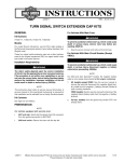
-J05656
REV. 2013-04-18
BOOM! AUDIO 6.5 IN FRONT FAIRING SPEAKER KIT
See the service manual to remove the main fuse. Turn ignition
switch OFF.
GENERAL
Kit Number
REMOVAL
76000317
Models
For model fitment information, see the P&A retail catalog or
the Parts and Accessories section of www.harley-davidson.com
(English only).
NOTE
The speakers in this kit are for use ONLY on specific 2014 and
later Harley-Davidson audio systems. See the P&A retail
catalog or the Parts and Accessories section of www.harleydavidson.com (English only).
Using these speakers on 2005 or earlier Harley-Davidson audio
systems WILL permanently damage those systems.
1.
Remove the outer fairing and windshield per the service
manual.
2.
See Figure 1. Remove the harness anchor (2) from each
speaker enclosure (1). Retain all fasteners for installation.
3.
Unplug the speaker connector (3) on one enclosure.
4.
Right side only: Unplug the power outlet connector
[C132B] (not shown).
Left side only, CB-equipped models: Unplug the CB
connector [184] (4) and CB antenna. See the service
manual.
5.
Remove the three screws (6) securing the lower portion
of the enclosure to the fairing support bracket (5).
6.
Remove two screws (8) securing the upper portion of the
enclosure to the upper support bracket (7).
Installation Requirements
The rider's safety depends upon the correct installation
of this kit. Use the appropriate service manual procedures.
If the procedure is not within your capabilities or you do
not have the correct tools, have a Harley-Davidson dealer
perform the installation. Improper installation of this kit
could result in death or serious injury. (00333a)
NOTE
This instruction sheet refers to service manual information. A
service manual for this year/model motorcycle is required for
this installation. One is available from a Harley-Davidson dealer.
7.
Remove three screws (9) securing the speaker enclosure
to the inner fairing. Remove the speaker enclosure from
the vehicle.
8.
Remove four screws (12) to free the speaker (11) from
the enclosure.
9.
Disconnect wires (13). Remove the speaker from the
enclosure.
10. Remove the three screws (15) securing the speaker grille
(14) to the inner fairing. Remove the speaker grille from
the fairing.
Kit Contents
See Figure 2 and Table 1.
PREPARATION
NOTE
For vehicles equipped with security siren: With security fob
present, turn ignition switch ON.
To prevent accidental vehicle start-up, which could cause
death or serious injury, remove main fuse before proceeding. (00251b)
-J05656
NOTE
Do not remove any of the screws (10) securing the speaker
enclosure halves together.
11. Repeat steps 3-10 to remove the remaining speaker
enclosure.
NOTE
Never operate the vehicle with the speaker enclosures
removed. The enclosures provide important structural support
to the fairing. Operating without the enclosures in place can
result in damage to the fairing assembly.
Many Harley-Davidson® Parts & Accessories are made of plastics and metals which can be recycled.
Please dispose of materials responsibly.
1 of 3
14
is07432
7
17
15
1
11
12
10
9
16
1
2
8
6
13
5
4
3
1.
2.
3.
4.
5.
6.
7.
8.
9.
10.
11.
12.
13.
14.
15.
16.
17.
Speaker enclosure
Fairing harness anchor
Speaker connector
CB connector
Fairing support bracket
Screw, hex head socket, 5/16-18 x 3/4 in (19 mm) long (3)
Upper support bracket
Screw, hex socket, 1/4-20 x 1/2 in (13 mm) long (2)
Screw, hex socket, 1/4-20 x 3/4 in (19 mm) long (3)
DO NOT remove these screws (13)
Original 5-1/4 in (133 mm) speaker
Screw, TORX, #10 x 1/2 in (13 mm) long (4)
Speaker wire connectors
Speaker grille
Screw, TORX, #10 x 3/8 in (10 mm) long (3)
Alignment pin
View in direction of arrow
Figure 1. Speaker Enclosure Removal (Left Side Shown)
INSTALLATION
3.
Attach the speaker wire connectors (13) inside one of the
speaker enclosures to the spade terminals on the back of
the new speaker. Different size spade contacts prevent
improper assembly.
NOTES
See Figure 2. The new speaker grilles are side-specific.
•
The shortest mounting tab (A) mounts to the inboard side
of the opening in the fairing.
4.
Install the speaker. Secure with four TORX screws (12)
removed earlier. Tighten to 14-20 in-lbs (1.6-2.3 Nm).
•
Verify proper orientation of the Bar & Shield emblem before
proceeding.
5.
1.
Install the correct speaker grille (2 or 3) from the kit into
each side of the inner fairing. Secure with three TORX
screws (Figure 1, Item 15) removed earlier. Tighten to
9-13 in-lbs (1.0-1.4 Nm).
Install the speaker enclosure to the inner fairing. Secure
with three hex socket screws (9) removed earlier. Tighten
to 48-60 in-lbs (5.4-6.8 Nm).
6.
Secure the lower portion of the enclosure to the fairing
support bracket (5) with three hex head socket screws (6)
removed earlier. Tighten to 20-24 ft-lbs (27.1-32.5 Nm).
7.
Secure the enclosure to the upper support bracket with
two hex socket screws (8). Tighten to 48-60 in-lbs (5.46.8 Nm).
8.
Repeat steps 2-7 with the remaining enclosure.
9.
Mate the speaker and power outlet connectors. Secure
the harness anchors to the speaker enclosures.
2.
See Figure 2. Rotate the speaker assembly (1) so the
tweeter bridge (B) is 45 degrees outboard from the top.
Verify that hole (C) in the speaker frame mates with the
alignment pin (Figure 1 inset, Item 16) on the speaker
enclosure. Hole is marked "B" on left speaker, "A" on right
speaker.
-J05656
2 of 3
10. Left side only, CB-equipped models: Plug in the CB
connector [184] and CB antenna. See the service manual.
COMPLETION
SERVICE PARTS
is07433a
B
NOTE
1
To prevent possible damage to the sound system, verify that
the ignition is OFF before installing the main fuse.
1.
See the service manual to install the main fuse.
2.
Turn the ignition ON, but do not start the motorcycle.
C
B
NOTE
Before installing outer fairing, check that speakers are operating
correctly. Understand that buzzing, squeaks and rattles may
be heard until outer fairing is installed.
3.
4.
1
Refer to the PREMIUM SOUND SYSTEM section of the
owner's manual and turn the radio ON. Make sure that all
speakers are working and front/rear fader function is
operating correctly. If not, check speaker wiring.
2
A
3
See the service manual to install the outer fairing and
windshield.
C
After installing seat, pull upward on seat to be sure it is
locked in position. While riding, a loose seat can shift
causing loss of control, which could result in death or
serious injury. (00070b)
5.
Figure 2. Service Parts, Boom! Audio 6.5 in Front Fairing
Speaker Kit
See the service manual to install the seat.
IN USE
Avoid direct contact with speaker grilles by a pressure washer.
Damage to speakers can result.
Table 1. Service Parts
Item
Description (Quantity)
Part Number
1
Speaker assembly (2)
76000320
2
Woofer grille, left
76000322
3
Woofer grille, right
76000321
Item mentioned in text.
-J05656
A
Short mounting tab
B
Tweeter bridge
C
Alignment hole in speaker frame
Marked "A" (right speaker), "B" (left speaker)
3 of 3