1
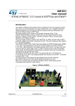
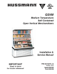
Hussmann® Impact™
Hot Food Merchandiser
MODEL WDCHI, SSWHI, TSWHI, CSWHI
Service Manual
Serial Numbers 121736 and Higher
Warranty Information
LIMITED ONE YEAR WARRANTY
BKI (The “Company”) warrants to the original purchaser/user, that at time of shipment from the
Company factory, this equipment will be free from defect in materials and workmanship. Written
notice of a claim under this Warranty must be given within ONE YEAR AND THREE MONTHS
from date of shipment from the factory. Defective conditions caused by abnormal use or misuse,
lack of maintenance, damage by third parties, alterations by unauthorized personnel, acts of God,
failure to follow installation instructions or any other events beyond the control of the company will
NOT be covered under Warranty. The obligation of the Company under this Warranty shall be
limited to repairing or replacing (at the option of the company) any part that is defective in
reasonable opinion of the Company. The user will have the responsibility and expense of
removing and returning the defective part to the Company as well as the cost of reinstalling the
replacement or repaired part.
IN NO EVENT SHALL THE COMPANY BE LIABLE FOR LOSS OF USE, LOSS OF REVENUE
OR LOSS OF PRODUCT OR PROFIT OR FOR INDIRECT OR CONSEQUENTIAL DAMAGES
INCLUDING BUT NOT LIMITED TO, FOOD SPOILAGE OR PRODUCT LOSS. WARRANTY
DOES NOT COVER GLASS BREAKAGE. THE ABOVE WARRANTY IS EXCLUSIVE AND ALL
OTHER WARRANTIES, EXPRESS OR IMPLIED, ARE EXCLUDED INCLUDING THE IMPLIED
WARRANTIES OF MERCHANTABILITY AND FITNESS FOR A PARTICULAR PURPOSE.
THIS WARRANTY SHALL APPLY ONLY WITHIN THE CONTINENTAL UNITED STATES, ITS
TERRITORIES, AND POSSESSIONS AND IN CANADA.
LIMITED NINETY DAY LABOR WARRANTY
All labor necessary to repair or replace factory defective parts will be performed, without charge,
to the end user, by service personnel of a BKI Authorized Distributor during the first ninety days
after the date of installation of the new equipment.
Replacement parts: Any appliance replacement part, except lamps and fuses, which proves to
be defective in material or workmanship within 90 days from date of original installation will be
repaired or replaced without charge F.O.B. Factory, Simpsonville, S.C. or F.O.B. authorized
distributor.
Hussmann® Impact™ Hot Food Merchandiser
Table of Contents
Table of Contents
Table of Contents........................................................................................................................................ 1
Introduction ................................................................................................................................................. 2
Safety Precautions.................................................................................................................................... 2
Safety Signs and Messages................................................................................................................. 2
Safe Work Practices ............................................................................................................................. 3
Safety Labels ............................................................................................................................................ 5
Installation ................................................................................................................................................... 6
NSF Certification....................................................................................................................................... 6
Location .................................................................................................................................................... 6
Shipping Damage ..................................................................................................................................... 7
Shipping Braces........................................................................................................................................ 7
Shipping Rider .......................................................................................................................................... 7
Case Leveling ........................................................................................................................................... 8
Preparation ........................................................................................................................................... 8
Leveler Adjustment............................................................................................................................... 8
Glass Positioning ...................................................................................................................................... 9
Raising/Lowering Glass Using Adjustment Bolt ................................................................................. 11
Joining Instructions ................................................................................................................................. 14
Wiring...................................................................................................................................................... 20
Installing Splashguard And Lower Front Panel ...................................................................................... 21
Splashguards...................................................................................................................................... 21
Lower Front Panel .............................................................................................................................. 21
Installing Bottom Rear Panel .................................................................................................................. 22
Replacement Parts.................................................................................................................................... 23
Control Plate ........................................................................................................................................... 23
Electrical Raceway ................................................................................................................................. 24
Canopy & Lift Hardware.......................................................................................................................... 25
Heated Shelf ........................................................................................................................................... 26
Wiring Diagrams........................................................................................................................................ 27
Notes .......................................................................................................................................................... 56
1
Hussmann® Impact™ Hot Food Merchandiser
Introduction
Introduction
Congratulations! You have chosen a Hot Food Merchandiser. It consists of thermostatically controlled hot
food waterless wells, canopy heaters/lighting, customer side curved glass service door with lift hardware,
operator side service doors, bumpers, splashguards and electronic controls.
This unit is manufactured by BKI which assures you of the finest in design and engineering -- that it has
been built with care and dedication -- using the best materials available. Attention to the operating
instructions regarding proper installation, operation, and maintenance will result in long lasting
dependability to insure the highest profitable return on your investment.
PLEASE READ THIS ENTIRE MANUAL BEFORE OPERATING THE UNIT. If
you have any questions, please contact your BKI Distributor. If they are unable to
answer your questions, contact the BKI Technical Service Department, toll free:
1-800-927-6887. Outside the U.S., call 1-864-963-3471.
This unit is to be sealed to the floor after installation to conform to NSF
requirements. (Dow Corning RTV #732 Multi purpose Sealant.)
Safety Precautions
Always follow recommended safety precautions listed in this manual. Below is the safety alert symbol.
When you see this symbol on your equipment, be alert to the potential for personal injury or property
damage.
Safety Signs and Messages
The following Safety signs and messages are placed in this manual to provide instructions and identify
specific areas where potential hazards exist and special precautions should be taken. Know and
understand the meaning of these instructions, signs, and messages. Damage to the equipment, death or
serious injury to you or other persons may result if these messages are not followed.
This message indicates an imminently hazardous situation which, if not avoided,
will result in death or serious injury.
This message indicates a potentially hazardous situation, which, if not avoided,
could result in death or serious injury.
This message indicates a potentially hazardous situation, which, if not avoided,
may result in minor or moderate injury. It may also be used to alert against unsafe
practices.
This message is used when special information, instructions or identification are
required relating to procedures, equipment, tools, capacities and other special
data.
2
Hussmann® Impact™ Hot Food Merchandiser
Introduction
Safe Work Practices
Beware of High Voltage
This equipment uses high voltage. Serious injury can occur if you or
any untrained or unauthorized person installs, services, or repairs this
equipment. Always Use an Authorized Service agent to Service Your
Equipment
Keep this manual with the Equipment
This manual is an important part of your equipment. Always keep it
near for easy access.
If you need to replace this manual, contact:
BKI
Technical Services Department
P.O. Box 80400
Simpsonville, S.C. 29680-0400
Or call toll free: 1-800-927-6887
Outside the U.S., call 864-963-3471
Protect Children
Keep children away from this equipment. Children may not understand
that this equipment is dangerous for them and others.
NEVER allow children to play near or operate your equipment.
Keep Safety Labels Clean and in Good Condition
Do not remove or cover any safety labels on your equipment. Keep all
safety labels clean and in good condition. Replace any damaged or
missing safety labels. Refer to the Safety Labels section for illustration
and location of safety labels on this unit. If you need a new safety
label, obtain the number of the specific label illustrated on page 5,
then contact:
BKI
Technical Services Department
P.O. Box 80400
Simpsonville, S.C. 29680-0400
Or call toll free: 1-800-927-6887
Outside the U.S., call 864-963-3471
3
Hussmann® Impact™ Hot Food Merchandiser
Introduction
Be Prepared for Emergencies
Be prepared for fires, injuries, or other emergencies.
911
Keep a first aid kit and a fire extinguisher near the equipment. You
must use a 40-pound Type BC fire extinguisher and keep it within 25
feet of your equipment.
Keep emergency numbers for doctors, ambulance services, hospitals,
and the fire department near your telephone.
Know your responsibilities as an Employer
• Make certain your employees know how to operate the equipment.
• Make certain your employees are aware of the safety precautions
on the equipment and in this manual.
• Make certain that you have thoroughly trained your employees
about operating the equipment safely.
• Make certain the equipment is in proper working condition. If you
make unauthorized modifications to the equipment, you will reduce
the function and safety of the equipment.
4
Hussmann® Impact™ Hot Food Merchandiser
Introduction
Safety Labels
5
Hussmann® Impact™ Hot Food Merchandiser
Installation
Installation
NSF Certification
This merchandiser is manufactured to meet ANSI/National Sanitation Foundation (NSF®) Standard #7
requirements. Proper installation is required to maintain certification.
Location
This merchandiser is designed for displaying products in air-conditioned stores where temperature is
maintained at or below the ANSI/NSF-7 specified level and relative humidity is maintained at or below
55%.
This merchandiser is sensitive to air disturbances. Air currents passing around the merchandiser will
seriously impair its operation. Do NOT allow air conditioning, electric fans, open doors or windows, etc. to
create air currents around the merchandiser.
The product should always be maintained at 145° F to maximize its display life.
Read before raising front glass.
The top cylinders, which allow the raising and lowering of this glass, have been
carefully installed and tested for the proper tension before shipment. However,
during shipment and storage, the lubricant inside the cylinders may have settled.
This settling can cause excessive or uneven tension on the glass to the point of
breakage.
To avoid any damage, please do the following before completely raising the
front glass.
1. Slowly raise and lower each glass section 6 times to a height of 6 in.
(152 mm).
2. Increase the height to about 12 in. (305 mm) and raise and lower the
glass 6 times.
3. Then raise the glass to the full extension and lower.
This should release any settled lubricant in the cylinders and prevent any stress
on the front glass.
Do NOT remove shipping braces until the merchandisers are positioned for
installation.
6
Hussmann® Impact™ Hot Food Merchandiser
Installation
Shipping Damage
YOU are responsible for filling all freight claims with the delivering truck line. Inspect all cartons and
crates for damage as soon as they arrive. If damage to cartons or crates is found, or if a shortage is
found, note this on the bill of lading (all copies) prior to signing.
If damage is found when the equipment is opened, immediately call the delivering truck line and follow up
the call with a written report indicating concealed damage to your shipment. Ask for an immediate
inspection of your concealed damage item. Packaging material MUST be retained to show the inspector
from the truck line.
Do not walk or put heavy object on top of merchandisers.
Damage to the merchandisers and serious personal injury could occur.
Merchandisers ARE NOT STRUCTURALLY DESIGNED TO SUPPORT EXCESSIVE
EXTERNAL LOADING such as the weight of a person. Do not place heavy objects
on the case.
Shipping Braces
Note: Be careful not to damage the factory-installed end while moving the case. Make sure that tools are
positioned past the end and beneath the merchandiser’s support bar.
Move the fixture as close as possible to its permanent location and then remove all packaging and
shipping braces. Check for damage before discarding packaging. Remove all separately packed
accessories such as kits, and shelves.
Remove all nut retainers used with shipping braces. NSF certification requires the use of ANSI Standard
nuts and bolts with not more than 2 threads showing after installation.
Shipping Rider
Each case is shipped on a rider to protect factory-installed legs, and to make positioning the case easier.
Remove the rider after the case has been positioned.
Note: Once the rider is removed, the case must be lifted –NOT PUSHED– to reposition.
To remove the rider, remove screws attaching each leg to rider. Remove screws holding rider crossmembers, then slide cross-members out from between sides. Once cross-members are out, slide the
sides out.
7
Hussmann® Impact™ Hot Food Merchandiser
Installation
Case Leveling
Merchandisers must be installed level to ensure proper operation. During all steps of setting, joining and
leveling cases, close attention to glass position and operation must be maintained. Please review all
steps and photos before making any adjustments. DO NOT make any glass adjustments until individual
case is set and level.
Preparation
1. Using store blueprints, measure off and mark on floor the exact dimensions/locations of the case
footprint.
2. Snap a chalk line for the front and rear positions of the base legs.
3. Mark the location of each joint from front to back lines.
4. FLOORS ARE NOT LEVEL!!! When working with two or more cases to be joined, the whole
lineup must be leveled on the same plane, left to right and front to back. This means that the
entire lineup must be brought up to the level of the highest case in the lineup.
Along the lines previously marked, find the highest point of the floor by:
•
•
•
Walking the floor and noticing any dips or mounds;
Using a string level; and
Using a transit.
Leveler Adjustment
Position the first case at the highest point. Set a long level (4 ft [1220 mm] or more) on the upper front
panel of the case. Use an open-end wrench to turn leg levelers until the case is level from end to end and
from front to back. Check all 6 legs on 8 ft (2438 mm) cases, or 8 legs on 12 ft (3658 mm) cases.
Note: To avoid removing concrete flooring, begin lineup leveling from the highest point of the store floor
8
Hussmann® Impact™ Hot Food Merchandiser
Installation
Attention to glass position is critical during the leveling process.
Adjusting leg levelers will affect the position of the glass. Make certain that the glass is square with the
case, avoiding interference with other glass and case ends.
If the glass is still out of alignment, refer to the following Glass Positioning instructions.
Glass must be properly supported when adjusting.
Glass Positioning
Follow the procedures below to improve the opening and closing of the case front glass.
1. Ensure the case has been leveled according to the Case Leveling procedure.
2. Ensure that the glass handle is installed correctly.
Verify the glass is bottomed out the length of the handle. A bowed handle indicates the glass may
not be bottomed out at the center of the handle.
The handle must be removed before it can be repositioned. The handle is held in place with
silicone that must be completely removed from the handle and the glass. Remove the handle by
pulling it away from the glass (do not use tools to pry this loose). A damaged or bent handle must
be replaced. Apply new silicone into the handle and firmly press onto the glass.
3. Ensure that the glass is seated in the clamp hardware correctly.
Verify glass is bottomed out in clamp hardware.
9
Hussmann® Impact™ Hot Food Merchandiser
Installation
If the glass is not bottomed out in the clamp hardware it can be re-positioned as follows:
a.
Remove the glass and clamp hardware from the case by opening the glass and loosening
set screws in hinge, (Metric 3 millimeter set screws).
b.
Slide the glass and clamp hardware to the side, out of the hinges, and lay them on an
appropriate work surface.
Note: adjacent glass must be closed.
c.
Loosen the 8 set screws on the underside of the clamp hardware.
d.
Push the clamp hardware onto the glass until bottomed out.
e.
The clamp hardware must overhang the glass by an equal amount on each side.
f.
Tighten set-screws and re-install on case.
4. Slowly open and close the glass to make sure that it is not hitting the end or adjacent glass. If the
glass is hitting the end or adjacent glass it may not be positioned correctly from left to right. This
can be adjusted as follows:
a.
Loosen the 2 screws holding the hinge to the clamp hardware (Metric 3 millimeter screws).
b.
Slide the clamp hardware to either side as needed.
10
Hussmann® Impact™ Hot Food Merchandiser
c.
Installation
Tighten the screws and check glass for proper operation.
5. Slowly open and close the glass to make sure that it is still not hitting adjacent glass.
Each glass has been shipped with a flexible wiper gasket attached to each side. These are
designed to overlap each other, sealing the gap between the glass and allowing side-to-side
glass adjustment. After all glass has been adjusted as defined in Step 4, the flexible portion of
one gasket at a joint may be trimmed with a razor knife. Be sure that the remaining wiper gasket
seals the gap. Verify proper operation.
Raising/Lowering Glass Using Adjustment Bolt
If the glass still does not open or close correctly, adjustment of the top frame may be necessary.
This case is equipped with an adjustment bolt at the top rear of the case to raise or lower the glass. This
allows for improvements in the glass operation and sealing. The following outlines how to access the
adjustment bolt. The top must be free to move as the adjustment bolt is turned.
1. Loosen joining or end bolts at top of case, (2 at each end of case).
2. If caulk or silicone has been applied between case joints or ends in the top area it must be
removed.
3. Remove rear doors.
11
Hussmann® Impact™ Hot Food Merchandiser
Installation
4. Remove screws at top of rear doorframe. The bottom screws do not need to be removed.
5. Pull back the top of the doorframe approximately 2 inches. This will allow clearance for removal of
the stainless steel top liner and trim pieces.
6. Some models have a Phillips truss head screw holding the stainless steel liner to the trim. These
screws are visible from the rear of the case to the side of the door frame. These must be
removed.
7. Remove stainless steel top liner by grabbing the rear flange and pulling back. Note: It is possible
to access the adjusting bolt by using a small swivel socket without removing the stainless top
liner. To do this, the stainless steel trim and foam noted in Step 8 must be removed.
8. Remove stainless steel trim pieces and foam insulation on each side of the doorframe.
9. The set screw and adjusting bolt are now accessible.
•
•
•
•
•
The set screw must be backed out before turning the adjusting bolt, (1/8 inch set screw). The
set screw serves as a positive stop.
The adjusting bolt should be turned no more than a half-turn before inspecting glass position
and operation.
Turning the adjusting bolt clockwise will raise the front glass.
Turning the adjusting bolt counter-clockwise will lower the front glass.
Once the glass position is set, tighten the set screw (positive stop).
12
Hussmann® Impact™ Hot Food Merchandiser
Installation
10. Once glass is positioned and operating correctly, re-install components and hardware removed.
Note: the doorframe is designed to have a tight fit. A putty knife between the top of the frame and the
insulated panel will help guide it into position.
11. Re-apply caulk or silicone as required.
12. Verify glass is positioned and operating correctly.
13
Hussmann® Impact™ Hot Food Merchandiser
Installation
Joining Instructions
1. Install the Top Gasket Pad (Item 4 and DETAIL F) and apply Silicone (Item 3 and DETAIL H-a).
14
Hussmann® Impact™ Hot Food Merchandiser
Installation
2. The complete lineup must be leveled to the highest point of the floor. After the first merchandiser
has been set, position the second so the end frames touch.
a. Set a long level (4 foot or more) on the upper front panel of the merchandisers. Adjust case
height by rotating the Adjustable Leg Leveler until the merchandisers are flush and level.
b. Also check each joint area to be sure that the panels of adjoining merchandisers are flush to
each other.
15
Hussmann® Impact™ Hot Food Merchandiser
Installation
3. Align the top extrusion and insert Joining Plate (Item 7).
4. Use 8-18 x 3/8 Truss Head SM Screws (Item 8) to fasten the plate using the predrilled pilot holes
as shown below.
5. Align the Rear Sill and attach Joining Bracket (Item 9) with 10-24 x ½ Washer Head Machine
Screws (Item 10). Use only specified fasteners. Longer screws will penetrate the Rear Sill
causing damage.
16
Hussmann® Impact™ Hot Food Merchandiser
Installation
6. Bolt the cases together according to the sequence illustrated below.
Note: Make sure that no more than (2) threads are exposed when the cases are bolted
together. If this does occur, the bolt should be shortened, replaced with a shorter bolt or
capped off according to NSF specifications.
Use caution when installing fasteners around wiring.
a. Fasten the fronts together using 5/16-18 x 1 Hex Head Cap Screws, 5/16 Flat Washers and
5/16 Lock Washers.
b. Fasten the rear of the cases together at two locations shown above using 5/16-18 x 1
Hex Head Cap Screws, 5/16 Flat Washers, 5/16 Lock Washers and 5/16-18 Hex Nut.
c.
Fasten the top rear of the cases together using 5/16-18 x 3 1/2 Cap Screws, 5/16 Flat
Washers, 5/16 Lock Washers and 5/16-18 Hex Nut.
17
Hussmann® Impact™ Hot Food Merchandiser
Installation
7. Apply a smooth continuous bead of silicone over the Exterior Top Joint (A.) of the cases.
Continue sealing down the Rear Mullion Joint (B.) of the cases and finally seal the Rear Sill Joints
(C.), as illustrated below.
18
Hussmann® Impact™ Hot Food Merchandiser
Installation
8. Install the Splashguard Joint Support (Item 25) to the splashguard retainer using #8 x 1/2 Hex
Head Sheet metal Screws (Item 26).
19
Hussmann® Impact™ Hot Food Merchandiser
Installation
Wiring
Electrocution, equipment failure or property damage could result if an unlicensed
electrician performs the electrical installation. Ensure that a licensed electrician
performs the electrical installation.
A wiring diagram for the specific model is shipped with the merchandiser. The wiring diagram provides
electrical specifications, an electrical schematic and a parts list. Refer to this wiring diagram and the
merchandiser serial number plate for electrical information.
Field wiring must be sized for the components amperes printed on the serial number plate. Actual ampere
draw may be less than specified.
All electrical connections should be in compliance with the NEC and all applicable local codes by a
licensed electrician. Refer to the wiring diagram furnished with your merchandiser for the electrical
specifications.
Follow the steps below to connect the power supply to the merchandiser. Refer to the figure below.
1. Remove the electrical raceway cover.
2. Two ¾” x 1” knockouts are provided for routing of power supply wiring. Route power supply wiring
through the knockout holes.
3. A power supply terminal block (TB0083) is located on the electrical raceway. Connect the wiring
to power supply terminal block (TB0083) according to the schematic provided.
4. Reattach the electrical raceway cover.
20
Hussmann® Impact™ Hot Food Merchandiser
Installation
Installing Splashguard And Lower Front Panel
Make certain that the end assemblies; end splashguards and end panels have been installed
according to the End Kit instruction.
The splashguard and lower front panel are shipped inside each case. After merchandisers have been
leveled, joined and electrical work has been completed, install the splashguard and lower front panel.
Splashguards
1. At front of merchandiser, attach a splashguard retainer/bracket to each leg with sheet metal
screws.
2. Position top of splashguard over the top edge of the retainer/bracket as shown below.
3. Push the lower edge of the splashguard toward the bottom of the bracket until it snaps into place.
Lower Front Panel
1. Position the lower front panel with the top angled as shown in the illustration. Tabs extending
from the upper front assembly are designed to fit into the slots on the top of the lower front panel.
21
Hussmann® Impact™ Hot Food Merchandiser
Installation
2. Once the top is positioned, lift the panel up and drop it into the groove at the top of the
splashguard.
Do not use additional fasteners or sealant to hold splashguards or panels in place. To meet NSF
cleaning requirements, splashguards and panels must be removable without tools.
Installing Bottom Rear Panel
For fixed installation:
1. Align slots in bottom rear panel with center of legs.
2. Drive a hex head sheet metal screw through each slot into each leg.
22
Hussmann® Impact™ Hot Food Merchandiser
Replacement Parts
Replacement Parts
Use the information in this section to identify replacement parts. To order replacement parts, call your
local BKI sales and service representative. Before calling, please note the serial number on the rating tag
affixed to the unit.
Control Plate
ITEM #
1
2
3
4
5
6
7
PART #
C0285
C0286
C0296
C0298
T0095
K0049
S0141*
K0040
TB0064
TB0065
TB0066
TB0067
TB0068
TB0069
PL0004
DESCRIPTION
CALROD, 208V 1000W
CALROD, 240V 1000W
CALROD, 208V 1112W
CALROD, 240V 1112W
THERMOSTAT, 250V 450 DEG
KNOB (FOR T0095)
SWITCH, INFINITE 240V-1245W
KNOB (FOR S0141)
TERM BLOCK 4 CONDUCTOR CTR
TERM BLOCK 4 CONDUCTOR W/MTG FOOT
TERM BLOCK 2 CONDUCTOR CTR
TERM BLOCK 2 CONDUCTOR
TERM BLOCK END PLATE
TERM BLOCK JUMPER BAR
PILOT LIGHT, ROUND 250V
* - Replace S0141 with assembly AN6778710S containing the S0141switch, B0058 bracket and NUT282
nut.
23
Hussmann® Impact™ Hot Food Merchandiser
Replacement Parts
Electrical Raceway
ITEM #
1
2
3
4
5
6
7
8
PART #
B0084
R0150
CB0065
S0356
TB0083
TB0024
TB0025-2
F0111
TB0066
TB0064
TB0065
TB0068
DESCRIPTION
BALLAST, 3XF32T8 OR 2XF40T8
RELAY, 4 POLE 208-240 60 HZ
BREAKER, CIRCUIT 2.5A 250V 2P
SWITCH, ROCKER 16A 250V
TERM BLOCK MDM10/5 70A 600V
TERM BLOCK JUMPER
TERM BLOCK
TERMINAL GROUNDING LUG
TERM BLOCK 2 CONDUCTOR CTR
TERM BLOCK 4 CONDUCTOR CTR
TERM BLOCK 4 CONDUCTOR W/MTG FOOT
TERM BLOCK END PLATE
24
Hussmann® Impact™ Hot Food Merchandiser
Replacement Parts
Canopy & Lift Hardware
ITEM #
1
2
3
4
5
6
PART #
FL0038*
FL0040*
HI0014
HI0013
C0057
I0029
HI0105**
HI0108**
VH0432**
VH0433**
DESCRIPTION
LAMP, FLUORESCENT F32T8/TL835/HV/ALTO
LAMP, FLUORES F25T8/TL835
LAMPHOLDER SHROUD, HI TEMP
HARNESS, 8FT LIGHT CHANNEL
CERAMIC HEATER 400W FULL SIZE 220/240V
FIBERGLASS SLEEVING SIZE 2 3.5"
GAS RAM 400N HUSSMANN IMPACT
GAS RAM 100N HUSSMANN IMPACT
GAS RAM 200 RADIAL HDWE
GAS RAM 300N RADIAL HDWE
* - To maintain NSF compliance, replace with BKI lamps only
** - Requires HI0110 Installation Tool
25
Hussmann® Impact™ Hot Food Merchandiser
Replacement Parts
Heated Shelf
ITEM #
1
2
3
4
5
6
7
8
PART #
FL0041*
FL0042*
FL0043*
HI0014
HI0013
C0081
C0082
C0085
C0086
T0006
G0108
G0110
G0112
G0113
G0109
G0111
K0050
DESCRIPTION
LAMP, FLUORESCENT GS U83001F25/T8 830
LAMP, FLUORESCENT GS U83321F32/T8 830
LAMP, FLUORESCENT GS U84001F40/T8 830
LAMPHOLDER SHROUD, HI TEMP
HARNESS, 8FT LIGHT CHANNEL
CALROD, 208V 1000W TSW4/8 SHELF
CALROD, 208V 1500W TSW6 SHELF
CALROD, 240V 1000W TSW4/8 SHELF
CALROD, 240V 1500W TSW6 SHELF
THERMOSTAT, 110/208 300 DEG
GUARD, FRONT SHELF TSW 48"
GUARD, FRONT SHELF TSW 72" CASE
GUARD, FRONT SHELF DRTSW 48"
GUARD, FRONT SHELF DRTSW 72"
GUARD, REAR SHELF TSW4-8
GUARD, REAR SHELF TSW6
KNOB (FOR T0006)
* - To maintain NSF compliance, replace with BKI lamps only.
26
Hussmann® Impact™ Hot Food Merchandiser
Wiring Diagrams
Wiring Diagrams
Refer to the table below to find the wiring diagram associated with your unit.
Wiring Diagram
Model SSWHI-4/CSWHI-4 208/220/240
Model SSWHI-6/CSWHI-6 208/220/240
Model SSWHI-8/CSWHI-8 208/220/240
Model TSWHI-4 208/220/240
Model TSWHI-6 208/220/240
Model TSWHI-8 208/220/240
Model WDCHI-3 208/220/240
Model WDCHI-4 208/220/240
Model WDCHI-4/2L
Model WDCHI-4/2R 208/220/240
Model WDCHI-4/4L 208/220/240
Model WDCHI-4/4R 208/220/240
Model WDCHI-5 208/220/240
Model WDCHI-6/2L 208/220/240
Model WDCHI-6/2R 208/220/240
Model WDCHI-7 208/220/240
Drawing #
SB68294600
SB68294700
SB68294800
SB68295100
SB68295200
SB68295300
SB68293600
SB68293700
SB68294000
SB68294100
SB68294200
SB68294300
SB68293800
SB68294400
SB68294500
SB68293900
27
Figure #
Figure 1
Figure 2
Figure 3
Figure 4
Figure 5
Figure 6
Figure 7
Figure 8
Figure 9
Figure 10
Figure 11
Figure 12
Figure 13
Figure 14
Figure 15
Figure 16
Page #
28
29
31
33
34
36
38
39
40
42
44
46
48
50
52
54
Hussmann® Impact™ Hot Food Merchandiser
Wiring Diagrams
Figure 1. Model SSWHI-4/CSWHI-4
28
Hussmann® Impact™ Hot Food Merchandiser
Wiring Diagrams
Figure 2. Model SSWHI-6/CSWHI-6 (Sheet 1 of 2)
29
Hussmann® Impact™ Hot Food Merchandiser
Wiring Diagrams
Figure 2. Model SSWHI-6/CSWHI-6 (Sheet 2 of 2)
30
Hussmann® Impact™ Hot Food Merchandiser
Wiring Diagrams
Figure 3. Model SSWHI-8/CSWHI-8 (Sheet 1 of 2)
31
Hussmann® Impact™ Hot Food Merchandiser
Wiring Diagrams
Figure 3. Model SSWHI-8/CSWHI-8 (Sheet 2 of 2)
32
Hussmann® Impact™ Hot Food Merchandiser
Wiring Diagrams
Figure 4. Model TSWHI-4
33
Hussmann® Impact™ Hot Food Merchandiser
Wiring Diagrams
Figure 5. Model TSWHI-6 (Sheet 1 of 2)
34
Hussmann® Impact™ Hot Food Merchandiser
Wiring Diagrams
Figure 5. Model TSWHI-6 (Sheet 2 of 2)
35
Hussmann® Impact™ Hot Food Merchandiser
Wiring Diagrams
Figure 6. Model TSWHI-8 (Sheet 1 of 2)
36
Hussmann® Impact™ Hot Food Merchandiser
Wiring Diagrams
Figure 6. Model TSWHI-8 (Sheet 2 of 2)
37
Hussmann® Impact™ Hot Food Merchandiser
Wiring Diagrams
Figure 7. Model WDCHI-3
38
Hussmann® Impact™ Hot Food Merchandiser
Wiring Diagrams
Figure 8. Model WDCHI-4
39
Hussmann® Impact™ Hot Food Merchandiser
Wiring Diagrams
Figure 9. Model WDCHI-4/2L (Sheet 1 of 2)
40
Hussmann® Impact™ Hot Food Merchandiser
Wiring Diagrams
Figure 9. Model WDCHI-4/2L (Sheet 2 of 2)
41
Hussmann® Impact™ Hot Food Merchandiser
Wiring Diagrams
Figure 10. Model WDCHI-4/2R (Sheet 1 of 2)
42
Hussmann® Impact™ Hot Food Merchandiser
Wiring Diagrams
Figure 10. Model WDCHI-4/2R (Sheet 2 of 2)
43
Hussmann® Impact™ Hot Food Merchandiser
Wiring Diagrams
Figure 11. Model WDCHI-4/4L (Sheet 1 of 2)
44
Hussmann® Impact™ Hot Food Merchandiser
Wiring Diagrams
Figure 11. Model WDCHI-4/4L (Sheet 2 of 2)
45
Hussmann® Impact™ Hot Food Merchandiser
Wiring Diagrams
Figure 12. Model WDCHI-4/4R (Sheet 1 of 2)
46
Hussmann® Impact™ Hot Food Merchandiser
Wiring Diagrams
Figure 12. Model WDCHI-4/4R (Sheet 2 of 2)
47
Hussmann® Impact™ Hot Food Merchandiser
Wiring Diagrams
Figure 13. Model WDCHI-5 (Sheet 1 of 2)
48
Hussmann® Impact™ Hot Food Merchandiser
Wiring Diagrams
Figure 13. Model WDCHI-5 (Sheet 2 of 2)
49
Hussmann® Impact™ Hot Food Merchandiser
Wiring Diagrams
Figure 14. Model WDCHI-6/2L (Sheet 1 of 2)
50
Hussmann® Impact™ Hot Food Merchandiser
Wiring Diagrams
Figure 14. Model WDCHI-6/2L (Sheet 2 of 2)
51
Hussmann® Impact™ Hot Food Merchandiser
Wiring Diagrams
Figure 15. Model WDCHI-6/2R (Sheet 1 of 2)
52
Hussmann® Impact™ Hot Food Merchandiser
Wiring Diagrams
Figure 15. Model WDCHI-6/2R (Sheet 2 of 2)
53
Hussmann® Impact™ Hot Food Merchandiser
Wiring Diagrams
Figure 16. Model WDCHI-7 (Sheet 1 of 2)
54
Hussmann® Impact™ Hot Food Merchandiser
Wiring Diagrams
Figure 16. Model WDCHI-7 (Sheet 2 of 2)
55
Hussmann® Impact™ Hot Food Merchandiser
Notes
Notes
56
Hussmann® Impact™ Hot Food Merchandiser
Notes
57
P.O. Box 80400, Simpsonville, S.C. 29680-0400, USA
http://www.bkideas.com
Made and printed in the U.S.A
LI0231/0604