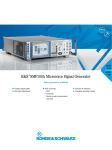
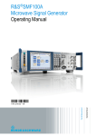
Download R&S®SMF100A Microwave generator
Transcript
Version 02.01 ¸SMF100A Microwave Signal Generator February 2009 Signal generation redefined ◆◆ Max. frequency range from 100 kHz to 43.5 GHz ◆◆ Excellent SSB phase noise of typ. –120 dBc (at 10 GHz; 10 kHz carrier offset) ◆◆ Very high output power of typ. +25 dBm SMF_bro_en_5213-7660-12_v0201.indd 1 ◆◆ Ideal in all areas –– R & D –– Production –– Service as well as maintenance and repair ◆◆ Remote control via GPIB, Ethernet or USB ◆◆ Innovative block diagram operation 13.02.2009 15:43:41 At a glance Signal quality, speed, and flexibility – these are decisive properties for a signal generator in the microwave range. a microwave signal generator, can be controlled via a block diagram – and the signal flow can be seen at a glance. Special features To meet even the highest of requirements, the ¸SMF100A microwave signal generator was completely redesigned and newly developed. The result is a first-rate, state-of-the-art microwave signal generator that sets new standards. It thus covers the numerous fields of application encountered in R & D, production, service, maintenance, and repair. The ¸SMF100A operates in the wide frequency range from 100 kHz to 43.5 GHz with specific configurations. In addition to CW signals, all common types of analog modulation (AM, FM, jM, pulse modulation) or combinations thereof can be generated. For just one example among many, take the following application: What can you do when cable loss at high frequencies starts becoming a larger and larger problem? Subsequent amplifiers represent one solution – or you can simply use the ¸SMF100A equipped with the ¸SMF-B32 or ¸SMF-B34 option that supplies a high output power of typ. +25 dBm at 20 GHz. The ¸SMF100A signal generator offers a modern graphical user interface for fast and intuitive operation. The settings – which, for the first time in 2 Excellent signal quality ◆ Exceptionally low single sideband phase noise: typ. –120 dBc (at 10 GHz; 10 kHz carrier offset; 1 Hz measurement bandwidth) ◆ Very low wideband noise: typ. <–148 dBc at 10 GHz (>10 MHz carrier offset; 1 Hz measurement bandwidth; at +10 dBm) ◆ Very low harmonics: typ. <–55 dBc at 10 GHz (at +10 dBm) ◆ High suppression of nonharmonics: typ. <–62 dBc at 10 GHz (>3 kHz carrier offset; at +10 dBm) Ideal for use in production ◆ Very short level and frequency setting times across entire level and frequency range: <4 ms (frequency), <3 ms (level), <700 µs (List mode; frequency and level) ◆ Very high output power of up to typ. +25 dBm ◆ Outstanding absolute level accuracy and level repeatability ◆ Selection of interfaces for remote control ◆ Low space requirement in rack: only three height units Aerospace & defense applications ◆ Optional pulse modulator with excellent data: >80 dB on/off ratio <10 ns rise/fall time <20 ns pulse width ◆ Optional pulse generator ◆ Optional pulse train ◆ Optional removable compact flash disk to meet high security requirements All-purpose applications ◆ Frequency range 100 kHz to 43.5 GHz ◆ Frequency, level, and LF sweeps ◆ AM, broadband FM, jM, pulse modulation ◆ Two multifunction generators up to 10 MHz ◆ Usable for scalar network analysis with ¸-NRP-Zx power sensor connected Intuitive operating concept ◆ Intuitive operating interface with graphical representation of the signal flow (block diagram) ◆ Operation with rotary knob on instrument or with USB mouse ◆ VGA color display with 640 pixels × 480 pixels Selection of interfaces ◆ Remote control via GPIB, Ethernet or USB ◆ USB ports for keyboard, mouse, and memory stick ◆ Connector for ¸NRP-Zx power sensors for precise power measurement ◆ Control via remote operation tool (e.g. VNC) ¸SMF100A Microwave Signal Generator SMF_bro_en_5213-7660-12_v0201.indd 2 13.02.2009 15:43:42 Everything in one instrument The ¸SMF100A base unit with frequency option included already offers the essential functions and interfaces. This basic configuration can be adapted to meet the requirements of further applications by adding specific options. The ¸SMF100A has outstanding specifications. Additional options for improving performance are not needed. This gives you a decisive advantage as the user. You no longer need to carry out tedious option configurations in order to increase performance. The base unit with frequency options included consists of the following: ◆◆ ¸SMF100A base unit plus ¸SMF-B122 frequency option (1 GHz to 22 GHz) ◆◆ ¸SMF100A base unit plus ¸SMF-B144 frequency option (1 GHz to 43.5 GHz) ◆◆ With the optional ¸SMF-B2 frequency extension plus one of the frequency options, the frequency range starts at 100 kHz Precise output level Precise and stable output levels are e ssential in a microwave signal generator. Furthermore, high r esolution is required when calibrating levels in measuring receivers. Therefore, the ¸SMF100A offers high-precision, frequency-response-corrected level control across the entire level range. Of course, the ¸SMF100A includes outstanding absolute level accuracy. But even more important is its level repeatability, since absolute errors can be c ompensated for by means of the a ppropriate corrections. Particularly in the case of repeatability, the ¸SMF100A sets new standards as shown in the figure below. Digital frequency and level sweep The digital frequency sweep makes it possible to perform frequency response measurements of microwave applications. Start and stop frequencies as well as step times are user-selectable. A trigger input enables synchronized operation with external equipment. The level sweep across any level range makes it possible, for example, to measure the compression characteristic of amplifiers or mixers. High frequency resolution To meet the high requirements of m any applications in research and science, the frequency options offer a frequency resolution of one-thousandth of a hertz (0.001 Hz) as standard. Measurement time in hours 0 5 0 18 000 10 15 20 25 30 35 40 0.05 0.04 Excellent spectral purity Absolutely no compromises have been made here. Everything technically feasible has been implemented. Both the SSB phase noise and the outstanding suppression of harmonics and nonharmonics earn top grades. This is a must for anyone working in the area of scalar network analysis, for example. 0.03 Level repeatability in dB This package contains the following as standard: 0.02 0.01 0 –0.01 –0.02 –0.03 –0.04 –0.05 36 000 54 000 72 000 90 000 Switching cycles 108 000 126 000 144 000 Level repeatability over time (with random frequency and level changes between measurements) SMF_bro_en_5213-7660-12_v0201.indd 3 ¸SMF100A Microwave Signal Generator 3 13.02.2009 15:43:51 Additional options The ¸SMF100A can be expanded with the following options in order to further adapt it to a wide variety of applications: Expanded level range For sensitivity measurements on receivers, very low levels are needed. With the optional ¸SMF-B26 or ¸SMF-B27 step attenuator, the lower level limit is shifted from –20 dBm without attenuator down to –130 dBm with attenuator. High output level In many microwave test setups, various equipment such as long cables, p ower splitters, directional couplers, or RF relays cause high loss. One possible solution here is an expensive exter- jM AM Log AM PM FSK PSK ASK FM – – – jM – – – AM – • – Log AM – • – PM • • – • FSK – – – – PSK – – – – ASK – – • – possible with no restrictions • possible with restrictions – not feasible nal microwave amplifier. But you can avoid this budget-consuming component by using the ¸SMF-B32 or ¸SMF‑B34 high output power option with up to typ. +25 dBm at 20 GHz. 35 Level in dBm FM With ¸SMF-B34 high output power option Without ¸SMF-B34 high output power option Output power of the ¸SMF-B2 frequency extension 30 AM, FM, jM, and Log AM including LF generators and noise generator The ¸SMF-B20 AM/FM/jM/LOG AM option complements the ¸SMF100A microwave signal generator. This expansion also includes two LF generators and a noise generator, making any combination of modulation modes possible. The table above provides an overview. 25 20 15 10 5 0 0 5 10 15 20 25 30 35 40 Frequency in GHz Maximum output power with and without the R&S®SMF-B34 high output power option in the frequency range 100 kHz to 43.5 GHz (¸SMF-B144 and ¸SMF-B2; with the R&S®SMF-B27 step attenuator option); the lower curve in the frequency range 100 kHz to 1 GHz is with activated pulse modulator of the R&S®SMF-B2 frequency extension 35 Level in dBm Modulation matrix With ¸SMF-B32 high output power option Without ¸SMF-B32 high output power option 30 25 20 15 Analog ramp sweep mode The analog ramp sweep mode (provided by the ¸SMF-K4 option) corresponds to the analog sweep of classic sweep generators except that the sweep is fully synchronized over the complete range. In this way, the excellent frequency accuracy of digital step sweeps is achieved on the whole, and this at much higher sweep rates of min. 700 MHz/ms at frequencies ≥3 GHz. High-end pulse modulation The ¸SMF100A can additionally be equipped with the ¸SMF-K3 pulse modulation option. Even high requirements are exceeded by an ON/OFF ratio of >80 dB, a rise/fall time of <10 ns, and a minimum pulse width of <20 ns. 10 5 0 0 5 10 15 20 Frequency in GHz Maximum output power with and without the R&S®SMF-B32 high output power option in the frequency range 1 GHz to 22 GHz (¸SMF-B122; in both cases with the R&S®SMF-B26 step attenuator option) 4 High-quality pulse generator In the case of pulsed signals, the combination of the ¸SMF‑K3 pulse modulator option and the internal ¸SMF‑K23 pulse generator option offers the ideal solution – particularly ¸SMF100A Microwave Signal Generator SMF_bro_en_5213-7660-12_v0201.indd 4 13.02.2009 15:43:52 if you do not have a high-quality pulse generator for testing. However, the internal pulse generator can also be used by itself in external applications via designated outputs. One new optional feature of the builtin pulse generator is the alternative to generate "pulse trains" (¸SMF-K27 option), which are commonly used for radar applications. An example of a pulse train is shown in the figure on the right. In contrast to single or double pulses, "pulse trains" are a combination of different pulses, which can be a periodical or non-periodical set of pulses. Highly stable output frequency The integrated reference oscillator included as standard keeps the output frequency precise and low in drift. To meet the highest of requirements in precision and aging, you can add the ¸SMF-B1 OCXO reference oscillator option to the ¸ SMF100A. T1 T3 Tn RF signal T2 Time t1 t2 t n-1 Pulse train: combination of pulses with different pulse widths and pauses Excellent signal quality Due to an innovative synthesizer concept, the ¸SMF100A o ffers e xcellent values in terms of SSB phase noise, wideband noise, and nonharmonics suppression. It is the ideal solution for all measurement a pplications in which the very high spectral purity of typ. –120 dBc (10 GHz; 10 kHz carrier offset; 1 Hz measurement bandwidth) is needed. For example, it can be used in communications systems as an IF or LO substitute for adjacent channel or phase noise mea- surements or in low-noise radar as an ultra-pure signal source. The ¸SMF100A offers this out standing signal quality because it includes an integrated reference oscillator as standard. You can improve this quality even further very near the carrier by a dding the ¸SMF-B22 enhanced phase noise option. –20 SSB phase noise in dBc (1 Hz measurement bandwidth) –30 –40 –50 –60 –70 –80 –90 –100 40 GHz –110 22 GHz –120 10 GHz –130 3 GHz –140 1 GHz –150 –160 1 10 100 1k 10k 100k 1M 10M Offset frequency in Hz Single sideband phase noise for various frequencies with the R&S®SMF-B22 enhanced phase noise performance option SMF_bro_en_5213-7660-12_v0201.indd 5 ¸SMF100A Microwave Signal Generator 5 13.02.2009 15:43:54 Ideal for use in production In production, high throughput and low test costs are the benchmarks by which a state-of-the-art microwave signal generator must be measured. The ¸SMF100A excels in this a rea by continuing the long t radition of very short level and frequency s etting times in signal generators from Rohde & Schwarz. These very short setting times in the millisecond range can be significantly reduced even further in the List mode. Here, the use of f requency and level pairs stored in a list brings setting times down to less than 700 µs when changing from one frequency and level pair to the next. In addition to very short setting times, a wide level range is also required. There are two reasons for this. First, sensitivity measurements demand very low levels, which can be set with the optional attenuators. Second, the microwave signal generator must compensate for loss in the test setup by means of correspondingly high output power. This must be done without having to rely on external amplifiers. The ¸SMF-B32 or ¸SMF-B34 high output p ower option, which has output power of typ. +25 dBm at 20 GHz, will meet your needs with power to spare. Furthermore, the production environment demands that measuring equipment be small in size. Occupying only three height units, the ¸SMF100A leaves ample space for other equipment in a rack. To meet the high security requirements demanded in aerospace & defense applications, the internal memory (compact flash disk containing all stored settings) can be shifted to the rear of the instrument (¸SMF-B85 option). The flash disk is then located in a slot and can be removed whenever necessary. Thus, sensitive data can always remain in a secured area. Intuitive operating concept Aerospace & defense The high requirements encountered in the aerospace & defense industry are met by the combination of the ¸SMF-K3 pulse modulator option and the ¸SMF‑K23 pulse generator option. For example, both single and double pulses can be generated with a delay. In addition, the pulse generator can generate pulse trains (¸SMF-K27 option), which are a combination of pulses with different widths and spacings between the pulses. State-of-the-art microwave signal generators offer a wealth of functions, internal boards, modules, and interfaces. When working with the instrument, you will especially appreciate its intuitive and fast operation as well as its straightforward display of the settings that have been made. In the ¸SMF100A, this is implemented by means of an easy-toread block diagram. You can immediately see which blocks can be called up for modulationor frequency settings, or which inputs and outputs have been enabled. Plus, your colleagues will benefit as well: All of them can see at a glance how the ¸SMF100A microwave s ignal generator is configured. The ¸SMF100A block diagram shows numerous settings, the signal flow, as well as active inputs and outputs in a straightforward manner 6 ¸SMF100A Microwave Signal Generator SMF_bro_en_5213-7660-12_v0201.indd 6 13.02.2009 15:43:54 Selection of interfaces The ¸SMF100A microwave signal generator can be remote-controlled via GPIB, LAN, or USB (LAN is part of the base unit). Slots are provided for the GPIB and USB options. The two spare slots can be used for a maximum of two of the following three options: ¸SMF-B83 removable GPIB, ¸SMF-B84 removable USB, or ¸SMF-B85 removable flash disk. For operating the instrument outside the security area, an optional spare CompactFlash™ memory card (¸SMF-Z10) is available on which no security-relevant data is stored. You can insert this spare card in the slot, switch on the signal generator, and then perform an internal instrument adjustment. The instrument is now ready for operation, calibration, or repair. Optional flash disk plug-in module, open (top) and closed Rear view of the ¸SMF100A with optional GPIB and USB (master and slave) interfaces ¸SMF100A Microwave Signal Generator SMF_bro_en_5213-7660-12_v0201.indd 7 7 13.02.2009 15:44:04 Suitable for all applications Scalar network analysis A common task in R&D or production is the adjustment of filters or the characterization of components. With its integrated List mode or its optional analog ramp sweep, the ¸SMF100A directly offers two ways of performing the measurements quickly and accurately. A major advantage in both modes is that frequency and linearity errors can be eliminated, as frequency generation is implemented in a synthesized (digital) manner. A third brand-new approach to scalar network analysis is provided by the power sensor connectivity of the ¸SMF100A plus the ¸SMF-K28 power analysis option. List mode Especially when the ¸SMF100A microwave signal generator is used together with a Rohde & Schwarz spectrum analyzer (¸FSP-B10 option), scalar network analysis can be performed selectively and very quickly. The distinguishing aspect is a large dynamic range with which, for example, filters in the passband and stopband can be measured even at small Scalar network analysis on a external bandpass filter (with ¸SMF-K28 power analysis option plus ¸NRP-Zx power sensor) levels. An adjustable frequency offset is also available for measuring frequencyconverting DUTs. (Note: The List mode in combination with the ¸FSP-B10 option requires that the ¸SMF-B83 removable GPIB option be installed.) Analog ramp sweep For the "realtime adjustment" of filters or components, very high sweep speed and sweep accuracy are required. The ¸SMF100A meets this requirement by means of the optional ¸SMF-K4 analog ramp sweep. This solution furthermore offers a higher frequency resolution than the List mode mentioned earlier. Scalar network analysis with an ¸NRP-Zx power sensor In the absence of spectrum or network analyzers scalar network analysis can be performed by means of the ¸SMF100A microwave signal generator with the ¸SMF-K28 power analysis option plus an ¸NRP-Zx power sensor. One example is to measure the passband characteristic of a bandpass filter. Scalar network analysis with the ¸SMF100A microwave signal generator and the ¸FSQ spectrum analyzer with the ¸FSP-B10 option installed 8 ¸SMF100A Microwave Signal Generator SMF_bro_en_5213-7660-12_v0201.indd 8 13.02.2009 15:44:09 The input of this filter is connected to the RF output whereas the output is connected to an ¸NRP-Zx power sensor. The power sensor itself is plugged to the sensor input of the ¸SMF100A. Based on the entered frequency range the ¸SMF100A performs the measurement and displays the passband of this bandpass filter. The filter can now be manually tuned and the adjustments can be directly controlled on the ¸SMF100A display. Setup on the ¸SMF100A Characteristic of a bandpass filter displayed by the ¸SMF100A (with the ¸SMF-K28 power analysis option installed) User-defined correction of external frequency responses DUTs such as power amplifiers always have frequency responses. In t hese cases, the signal generator needs to compensate for the frequency r esponse. The ¸SMF100A offers the User C orrection function for precisely this purpose. For a known frequency response that needs to be corrected, you can enter the level correction values as a function of the frequency. Automatic interpolation of the correction values is performed between these frequency points. To simplify this, the ¸SMF100A can also automatically include the level correction values at the press of a button by using external Rohde & Schwarz power sensors. ¸SMF100A Amplifier 2.5 Level in dB 2 Without frequency response correction With frequency response correction 1.5 1 0.5 User correction table with frequency and level correction entries in Hz and dB, respectively 0 –0.5 –1 –1.5 Frequency Output level of the ¸SMF100A microwave signal generator with (red) and without (yellow) frequency response correction SMF_bro_en_5213-7660-12_v0201.indd 9 ¸SMF100A Microwave Signal Generator 9 13.02.2009 15:44:20 The figure on the right shows the compensated frequency response of the amplifier with activated "User correction" (straight line at 5.7 dBm starting at 2.5 GHz up to 3.5 GHz). This procedure ensures that only the frequency response of a bandpass filter is measured, for example, but not the combined frequency response of amplifier and bandpass. Output characteristic of an amplifier obtained by applying “User Correction”, with the ¸SMF-K28 power analysis option installed. LO with exceptionally low SSB phase noise Because of its very low SSB phase noise, the ¸SMF100A can be used for a wide variety of applications. However, there are applications that require "worse" SSB phase noise for testing. For these cases, the ¸SMF100A offers a unique f unction: FM-modulated noise enables you to artificially degrade the instrument's low SSB phase noise in order to test the response of an oscillator or synthesizer, for example. The figure shows an unmodulated CW signal and a signal that is FM-modulated with noise. By varying the FM deviation, you can degrade the SSB phase noise. CW RBW 50 kHz Ref 10 dBm Att 35 dB Ref 10 dBm Att 35 dB VBW 200 kHz SWT 20 ms Ref A A 0 1 SA AVG -10 -20 -20 -20 -30 -30 -30 -40 -40 -40 -50 -50 -50 -60 -60 -60 -70 -70 -70 -80 -80 -80 -90 -90 Center 5 GHz 200 kHz/ Span 2 MHz Center Att 35 dB VBW 200 kHz SWT 20 ms A 0 1 SA AVG -10 -10 10 dBm 10 10 0 1 SA AVG RBW 50 kHz RBW 50 kHz VBW 200 kHz SWT 20 ms 10 -90 5 GHz 200 kHz/ Span 2 MHz Center 5 GHz 200 kHz/ Span 2 MHz The ¸SMF100A in the "FM-modulated noise" application 10 ¸SMF100A Microwave Signal Generator SMF_bro_en_5213-7660-12_v0201.indd 10 13.02.2009 15:44:21 Aerospace & defense applications The ¸SMF100A can also be used in pulse radar applications with a rotating antenna. In the example (see figure), the external pulse from the pulse generator is applied to the external pulse input of the ¸SMF100A and used as a trigger for the internal pulse generator and modulator. You can delay this trigger in order to perform distance and direction simulations and check them on the radar equipment's display. Circulator Antenna Pulsed transmitter Pulse 1 LO RF Pulse generator 2 Sideband filter Display Antenna direction pulse Testing of the distance and antenna direction display of the radar equipment T1 T1 T1 RF signal T1 Time t1 t1 t1 Single pulses T1 T1 T1 T1 T1 T1 RF signal For generating more complex pulse scenarios, the ¸SMF100A offers a new feature – based on its pulse modulator and pulse generator concept – using the ¸SMF-K27 pulse train option. In contrast to single or double pulses, "pulse trains" are a combination of different pulses, which can be a periodical or non-periodical set of pulses. The built-in optional pulse generator makes it now possible to generate these "pulse trains", which are commonly used for radar applications. Pulse width as well as pulse pause can be set independently and separately for each pulse. This makes it possible to generate staggered pulses or to apply jitter to pulse width as well as pulse pause. Time In contrast to ARB solutions, the greatest advantage is the much better performance of the pulse modulator with respect to ON/OFF ratio, rise and fall time, etc. t1 t2 t1 t2 t1 Double pulses T1 T3 Tn RF signal T2 Time t1 t2 t n-1 Pulse train (with the ¸SMF-K27 pulse train option) ¸SMF100A Microwave Signal Generator SMF_bro_en_5213-7660-12_v0201.indd 11 11 13.02.2009 15:44:21 Special features A unique feature of this microwave signal generator is that it allows you to directly connect an ¸NRP-Zx power sensor. This has its advantages. The power sensor enables you to measure the power directly before the DUT and display it on the ¸SMF100A. Irrespective of cable loss values or any components connected between the DUT and signal generator, you can thus set the desired power on the DUT by using the ¸SMF100A microwave signal generator. An ¸NRP-Zx power sensor attached at the sensor connector Another advantage becomes evident in the case of applications that require very high absolute level accuracy: The ¸SMF100A can measure its own output power via an attached power sensor. Manual adjustment capability allows you to increase the instrument's exceptional absolute level accuracy even further. You can operate the instrument both via the front-panel control elements or via a USB keyboard and USB mouse. To permit this, the front panel of the instrument provides two USB interfaces. In addition, an extra USB port is available on the rear panel (¸SMF-B84 option, master and slave USB). ¸NRP-Z55 power sensor connected to the ¸SMF100A RF output: The measurement result is displayed in the upper right of the block diagram The following question arises in many applications: How can I transfer instrument settings from one instrument to the other quickly and without errors? The solution is to use a memory stick. You merely need to use Save/Recall to quickly transfer instrument settings to a different ¸SMF100A. The ¸SMF100A with USB mouse and keyboard attached 12 ¸SMF100A Microwave Signal Generator SMF_bro_en_5213-7660-12_v0201.indd 12 13.02.2009 15:44:42 Specifications in brief Frequency Frequency range 100 kHz to 43.5 GHz Setting time <4 ms Setting time in List mode typ. <700 µs Level Setting range –130 dBm to +30 dBm Setting time <3 ms Setting time in List mode <700 µs Spectral purity SSB phase noise (at f = 10 GHz; 10 kHz carrier offset; 1 Hz measurement bandwidth) Supported modulation types with ¸SMF-B20 option Interfaces <–115 dBc (typ. –120 dBc) AM/FM/ϕM/LOG AM Standard LAN (100BaseT), 2 × USB With ¸SMF-B83 option IEEE 488.2 With ¸SMF-B84 option 1 × USB, 1 × USB slave With ¸SMF-B85 option removable flash disk SMF_bro_en_5213-7660-12_v0201.indd 13 ¸SMF100A Microwave Signal Generator 13 13.02.2009 15:44:42 Ordering information Designation Type Order No. Microwave Signal Generator 1) Including power cable, Quick Start Guide, and CD-ROM (with operating and service manual) ¸SMF100A 1167.0000.02 Frequency Range 1 GHz to 22 GHz 2) (3.5 mm female adapter included) ¸SMF-B122 1167.7004.03 Frequency Range 1 GHz to 43.5 GHz 2) (2.4 mm female and 2.9 mm female adapter included) ¸SMF-B144 1167.7204.03 OCXO Reference Oscillator 3) 4) ¸SMF-B1 1167.9159.02 Frequency Extension 100 kHz to 1 GHz ¸SMF-B2 1167.4005.02 AM/FM/φM/LOG AM Modulator 3) ¸SMF-B20 1167.9594.02 Enhanced Phase Noise Performance 3) R&S®SMF-B22 1415.2204.02 Step Attenuator 100 kHz to 22 GHz 3) ¸SMF-B26 1167.5553.02 Step Attenuator 100 kHz to 43.5 GHz 3) ¸SMF-B27 1167.5776.02 High Output Power (not in combination with R&S®SMF-B2) R&S®SMF-B32 1415.2304.02 High Output Power (in combination with R&S®SMF-B2) 3) R&S®SMF-B34 1415.2404.02 Rear Connectors 22 GHz ¸SMF-B81 1167.5999.02 Rear Connectors 43.5 GHz 3) ¸SMF-B82 1167.6208.02 Removable GPIB ¸SMF-B83 1167.6408.02 Removable USB 5) ¸SMF-B84 1167.6608.02 Removable Flash Disk 3) 5) ¸SMF-B85 1167.6808.02 Narrow Pulse Modulation ¸SMF-K3 1167.7804.02 Ramp Sweep ¸SMF-K4 1167.7604.02 Pulse Generator ¸SMF-K23 1167.7704.02 Pulse Train ¸SMF-K27 1415.2004.02 Power Analysis ¸SMF-K28 1415.2104.02 Two-year Calibration Option ¸CO2SMF100A 1167.0000S15 Three-year Calibration Option ¸CO3SMF100A 1167.0000S11 Five-year Calibration Option ¸CO5SMF100A 1167.0000S13 Two-year Repair Option ¸RO2SMF100A 1167.0000S16 Three-year Repair Option ¸RO3SMF100A 1167.0000S12 Five-year Repair Option ¸RO5SMF100A 1167.0000S14 Documentation of Calibration Values ¸DCV-2 0240.2193.19 DKD (ISO 17025) Calibration including ISO 9000 calibration (can only be ordered with the instrument) ¸SMF22-DKD 1161.3594.00 DKD (ISO 17025) Calibration including ISO 9000 calibration (can only be ordered with the instrument) ¸SMF44-DKD 1161.3620.00 Options 3) 3) 3) 5) Service options 14 ¸SMF100A Microwave Signal Generator SMF_bro_en_5213-7660-12_v0201.indd 14 13.02.2009 15:44:42 Designation Type Order No. R&S®NRP-Z81 1137.9009.02 Recommended extras Wideband Power Sensor (for use with R&S®SMF-K28) Hardcopy manuals (in English, UK) 1167.2319.32 Hardcopy manuals (in English, US) 1167.2319.39 Spare CompactFlash™ memory card (¸SMF-B85 required) ¸SMF-Z10 1167.8100.02 19" Rack Adapter ¸ZZA-311 1096.3277.00 Keyboard with USB Interface (US character set) ¸PSL-Z2 1157.6870.04 Mouse with USB Interface, optical ¸PSL-Z10 1157.7060.03 External USB DVD Drive ¸PSP-B6 1134.8201.22 Adapters for the ¸SMF100A with the ¸SMF-B122 frequency option 3.5 mm female 1021.0512.00 3.5 mm male 1021.0529.00 N female 1021.0535.00 N male 1021.0541.00 Adapters for the ¸SMF100A with the ¸SMF-B144 frequency option 2) 3) 4) 5) 1) 2.4 mm female 1088.1627.02 2.9 mm female 1036.4790.00 2.9 mm male 1036.4802.00 N female 1036.4777.00 N male 1036.4783.00 The base unit can only be ordered together with the ¸SMF-B122 or ¸SMF-B144 frequency option. Option fitted by factory. Option fitted by factory or especially equipped Rohde & Schwarz service department. Option cannot be installed with an R&S®SMF-B22 enhanced phase noise performance option (not required). Only two of the three options ¸SMF-B83, ¸SMF-B84, and ¸SMF-B85 can be installed simultaneously. SMF_bro_en_5213-7660-12_v0201.indd 15 ¸SMF100A Microwave Signal Generator 15 13.02.2009 15:44:42 Certified Environmental System ISO 9001 ISO 14001 DQS REG. NO 1954 QM DQS REG. NO 1954 UM For data sheet, see PD 5213.7660.22 and www.rohde-schwarz.com ¸ is a registered trademark of Rohde & Schwarz GmbH & Co. KG · Trade names are trademarks of the owners · PD 5213.7660.12 · Version 02.01 · February 2009 · R&S®SMF100A · Data without tolerance limits is not binding · Subject to change Printed in Germany (ch) *0.14 €/min within German wireline network; rates may vary in other networks (wireline and mobile) and countries. Certified Quality System www.rohde-schwarz.com Europe, Africa, Middle East +49 1805 12 42 42* or +49 89 4129 137 74 [email protected] North America +1-888-TEST-RSA (1-888-837-8772) [email protected] Latin America +1-410-910-7988 [email protected] Asia/Pacific +65 65 13 04 88 [email protected] SMF_bro_en_5213-7660-12_v0201.indd 16 13.02.2009 15:44:43


