1
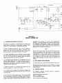
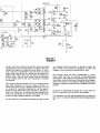
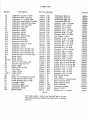
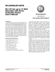
INSTALLATION &
OPERAI1:DN INSTRUCTiONs
ORDER NO.
640
SECTION I
GENERAL DESCRIPTION
. The Fqotlocker Linear Amplifier
is a precision built
. amplifier of advanced design. It utilizes two tubes, six
transistors in a tuned grid tuned plate circuit for amplification of AM, FM, CW and SSBsignals.
The Footlocker is designed for 12 DC negative ground
mobile installation and is supplied with a remote ON/OFF
switch which allows the operator to trunk-mount the Footlocker.
The Footlocker has a built-in automatic antenna change
over relay, which operates without special external connections, making it perfect for operation with low power
transceivers having no external amplifier control circuits.
The Footlocker has been designed and constructed to suppress radiation that may cause television interference.
TVI problem has been given full consideration in the
design and the layout of the chassis. There are, however,
some types of TVI that cannot be prevented within the
amplifier.
This is particularly true in weak signal areas.
In such cases, a good commercial low pass filter is recommended.
Height (including feet)
59/16"
Width
,
,
14"
Depth . . . . . . . . . . . . . . . . • . . . . . . . . . . . . . . . . . . . . . . 11 1/2"
Net Weight
,
9 Ibs.
Shipping Weight
10 Ibs.
Construction
Lightweight aluminum chassis with
rugged steel cover
Frequency Range
Types of Emission
Power Output.
Amateur 10 meter band
AM, FM, CW, SSB, DSB
200 watts AM with full upward
modulation
Drive Required to Trigger Antenna Relay
1 watt
Max Drive (unmodulated carrier and FM)
5 watts
(amplitude modulated carrier)
3.5 watts
(amplitude modulated peak) ..•...
14 watts PEP
Input Impedance (unbalanced)
50 ohms nominal
Output Impedance (unbalanced)
50 ohms fixed
Antenna Switching
,
Automatic provided by
RF sensing circuit
Power Requirements
13.6 volts (12 v nominal)
50 amps
Cable Connector Data ..... Input & Output requires PL-259
SECTION II
UNPACKI NG
Carefully
Examine
spection
contacted
remove the Footlocker Ampl ifier from the carton.
it closely for signs of shipping damage. If inshows damage, the del iveri ng carrier must be
·immediately and a claim filed.
The responsibility for safe delivery rests with the carrier.
The responsibi I ity of obtaining reimbursement rests with
you. Prompt action will speed adjustment. Our warranty
does not cover malfunction or damage which is a result of
improper handling by a carrier.
SECTION III
I NSTALLATI ON
The location of the mounting is not critical, however, the
Footlocker was designed to be mounted on the floor of the
trunk. Four support legs are provided to secure the Footlocker to the trunk floor. These support legs attach to the
Footlocker by means of the screws that hold the feet on.
Unscrew the feet, put the support legs on the screws and
put the feet back on.
~
1=
I
Jhe Footlocker draws up to 50 amps of current when transmitting.
If the electrical system of your vehicle is not
capable of supplying this current at 13.6 volts, then full
RF power output will not be achieved.
Connect the Footlocker directly to·· the vehicleb~lttery
using #6 or heavier wire for both positive and negative.
The vehicle chassis is a poor ground return path at this
current and should not be used. As an added safety precaution, it is strongly recommended that an additional 40
amp fuse and holder (the type obtainable from most electricalcontractor
supply stores) be inserted in the line
directly at the positive terminal. This wi II protect battery
should a short circuit develop in the wires going to the
Footlocker.
OBSERVE POLARITY; positive to +12v termina/and
negative to -12v terminal .. REVERSING POLARITY WILL CAUSE
DAMAGE TO VEHICLE AND FOOTLOCKER.
Connect a length of coaxial cable (RG 58/U
between the transceiver and XCVR socket.
or similar)
I
I
Cons.ideration must be given to provide adequate venti lation and to enable the operator to set up and check the
Footlocker when it is installed.
The Remote Switch should be mounted in a convenient
position on the dash. The two wires should be routed
back to the Footlocker and connected to the terminal strap
marked "Remote".
Make sure that the red wire goes to
the red terminal and the black wire to the black terminal.
A good ground should be made on the remote switch
through the mounting lugs, otherwise the ON/OFF indicator
lamp will not light when the Footlocker is switched to ON.
Before connecting the primary power cables to 'the supply
and the battery terminals, the voltage output of the generator or alternator should be checked." Turn on the car
headlights for five minutes without starting the motor.
This wi II discharge the battery sl ightly. Connect an accurate voltmeter from the generator output terminal to
ground and start the motor. WITH THE MOTORAT A FAST
IDLE, THE GENERATOROR ALTERNATOROUTPUT VOLTAGE
SHOULD NOT EXCEED 14.5 VOLTS. If it does, the automotive voltage regulator should be recalibrated for a
maximum output voltage from the generator or alternator of
14.5 volts.
If the generator output voltage is between
13.5 and 14.5 volts, the regulator will not need adjustment.
(For regulator adjustment, refer to the shop service manual
for the automobile avai lable from your car dealer.)
The antenna system should be checked for VSWRof less
than 2: 1 before the Footlocker is used. For best performance of your communication system the VSWRshould be
as low aspossible.
When the Footlocker is installed as outlined above, operation is simply achieved by switching the remote unit ON
and OFF. This controls the Footlocker. A built-in delay
in the automatic antenna change over holds the relay in
for about one second. Thi s is to prevent chatter when
using SSB(single side band) transceivers.'
Set the sl ide switch on the rear panel to the TUNE positipn. Adjust the drive control for midway position. Apply
3.5 watts drive power by keyin"g the transceiv~r microphone and quickly adjust the tune control for maximum
reading on the output meter. Remove the drive power after
adjustment.
Do not apply drive power for more than five ..seconds
without adjusting the tune control or damage to the tubes
can result.
Reapply drive power and adjust the drive control so that
the ampl ifier produces about 100 watts (about 5-6 on the
meter).
Adjustment of the input tuning coil (on the underside of
the Footlocker), using a hex shaped plastic al ignment
tool, may be necessary to achieve maximum power output.
Set the Tune-Operate slide switch to the Operate position.
Reapply drive power and adjust the drive control maximum
output, readjust the Tune and Input tuning coi I for maximum output.
The load capacitor is factory adjusted to provide maximum
output and should!12!. be adjusted.
Adjust the drive control until the. power output is about
150-200 watts. The amplifier is now adjusted to give 150
watts output with upward modulation to 300 watts.
2. If the output si gnal reproduced is identical to the
input, except stronger, the amplifier is said to be linear.
If not, the amplifier is non-linear.
3. Non-I inear operation produces spurious outputs and
distortion of the signal.
5. All power used to produce distortion and spurious
signals is power not being used for communication.
6. The Footlocker provides a 300 watt RF envelope maximum power output.
Always use a good peak reading watt meter such as the
Hy-Gain 421A when adjusting an amplifier.
If the average output power decreases with modulation
then either the transmitter (exciter) is i ncapabl e of upwa rd
modulation or the amplifier has not been tuned up correctly
and the above procedure should be rechecked.
If this
does not correct the situation, the drive control (on the
rear panel) should be adjusted for a sl ightly lower power
level necessary to produce upward modulation than a
carrier power of a higher level with downward modulation,
this will increase your communication range and provide
a clearer signal with much less distortion.
For best AM operation the I inear must be tuned according
to above procedures.
Many misconceptions regarding
I inear'operatioh exist among I inear users. Reviewi ng a
few points regarding proper linear operation will help to
7. Any attempt to operate AM at the 300 watt carri er
level will produce downward modulation with distortion
and spurious signa Is.
8. Distortion and spurious signals (lost power) will occur
in all I inear amps of operation at maximum carrier power is
attempted.
9. All Iinear amplifiers should be operated at about one
half the maximum carrier output to allow for modulation
expansion of the carrier.
10. Operation without leaving room for modulation expansion will not provide good communication.
The carrier
contributes nothing toward intelligibility,
only good modulation can carry intelligence. Running higher carrier power
and lower modulation is a detriment rather than an asset.
r-- - -- -.-- - - -- - - - -- -- - -- --- ~---- -- - •..
----!
I
".
,
I
~I
C6
.OOI;d2.5KV
~
R. F. POWER AMP.
,
1t.8t0
,,
I
326p1
-e
SI·I
I
,
I
l
I
I
1
I
rJ. _
,
I
1-(:1-------02
l
I
I
L
--RI-----.,
::1 '''n~,·,!
,"j~
I
POWER METER
I
J
I
I
R7
I
I
100.1\.
:
'
I
I
I
"0 ; :-
,
V2 I I
I
--I
age8, I
I
I I
I!
I
I
I
I
I
I, ~
122
CIII
I,
I
I
,L
!5 !·1
I I
I I
_
IW
______
.+--J
I'
I
RII
33
L __
SECTION IV
SERVI CE INFORMATION
DO NOT ship equipment to the Manufacturer without prior
authorization. We prefer to send special shipping labels
which willavoid the delay of unexpected shipment.
If time is extremely important, wire or call for approval
and we will rush labels to you. When a shipment is expected,even the time of sending the labels is less than
that lost when an unexpected shipment is received.
It is VERY IMPORTANT that the shipment be well packed
and fully insured. Damage claims must be settled between
you and the carrier and will greatly delay any returns.
Proper packing normally avoids this trouble.
ALL SHIPMENTSMUST BE SENT TO US PREPAID. We do not
accept collect shipments. All returns should be made in
our standard cartons only - so save your carton when unpacki ng the unit. When a shipment is returned it wi II be
handled in one of three ways ...
1 - Where all service is in warranty the shipment will be
returned prepaid by a carrier of our choice.
2 - If there are any charges not covered by warranty we
wi II hold the shipment and advi se you of costs, wh ich you
can then send.
3 - Or, upon your written authorization, we will ship COD
for any charges not covered by warranty, then the carri er
wi II coil ect these charges and the transportation costs on
arrival. Unclaimed or refused COD shipments will not be
reshipped until payment of service and transportation
charges is received. Shipment wi II then be made collect
for reshipment transportation charges. Unclaimed equipment automatically becomes the property of the Manufacturer 60 days after date of refusal or return and wi II be
disposed of for payment of charge due.
We WILL NOT ship by means of a carrier that will not fully
insure the shipment. Some carriers have a $200.00 limit.
The exception to this is when there is no other means
(APO-FPO-etc.j of shipment than parcel post; and then we
will ship by this means with your written agreement that
you aSSume any loss over that which the carrier will
insure. COD shipments cannot be made to APO-FPO addresses.
All replacement parts orders must be prepaid or COD only.
Replacement part price quotes wi II be furni shed on request
for those who desi re prepaid shipment or cannot accept
COD shipments.
All requests, inqui ries, warranty
returns should be made to:
Hy-Gain Electronics Corporation
8601 N.E. Highway 6
Lincoln, Nebraska 68507
Attn: Customer Service Manager
claims
or equipment
F2
40 AMI!
+12
[GNOO
voe
SECTION V
WARRANTY
Hy-Gai n Electronics Corporation warrants each new product
manufactured to be free from defects in material and workmanship and agrees to remedy any such defect, or to furni sh a new part, in exchange for any part of any uni t which
under normal installation, use, and service discloses such
defect within ninety days from the date of purchase by
original owner. The unit serial number must be registered
by the original owner at the time of purchase to val idate
the warranty.
This warranty does not extend to any of our products which
have been subjected to mis-use, neglect, accident, incorrect wiring not our own, improper installation or to use
in violation of instructions furnished by us. Nor does it
extend to units which have been repaired or altered outsi de of our factory nor to accessori es used therewi th not
of our own manufacture, nor to any cases where the serial
number has been removed, defaced, or changed.
Hy-Gain Electronics Corporation reserves the right to make
any changes deemed necessary or desi rabl e without advance notice or incurring any obi igation to make like
changes in units previously manufactured or sold.
Thi s warranty does not cover transportation or installation costs that may be incurred. HY-Gain Electronics
Corporation's sole liability is the remedy of any defect for
ninety days.Hy-Gain Electronics Corporation is not responsible for personal injury or property damage resulting from
improper or careless installation not intended by the manufacturer.
No person is authorized to assume for us any other liability in connection with the sale of our products.
All warranties are void and terminated one year after the
last unit of its type and design has been manufactured by
us.
PARTS LIST
Symbol
C1
C2
C3
C4
C5
C6
C7
C8
C9
C10
C11
C12
C13
C14
C15
C23
C17
C18
C19
C20
C21
C22
D1
D2
D3-D11.
F1
F2
K1
K2
L1
L2
L3 & 4
L5
M1
N1
N2
PI
P2
Q1
Q2
D12
Part
Description
Capacitor 2. 2'pf Cer Disc
Capacitor 20 pf Cer Disc
Capacitor 0.1 uf Flat Film
Capacitor-Load
326 pf Variable
Capacitor-Tune
50pf Variable
Capacitor.
001 uf 2.5 KV
Capacitor 10pf 3KV
Capacitor.
001 uf
Capacitor.
390 pf
Capacitor.
001 uf
Capacitor 2200 pf
Capacitor . 003 uf 3 KV
Capacitor 6800 pf
Capacitor 10 uf Ele
Capacitor 500 uf Ele
Capacitor 20 pf Cer Disc
Capacitor . 001 uf
Capacitor,
001 uf
Capacitor 40uf 450VDC Ele
Capacitor 40uf 450VDC Ele
Capacitor 40uf 450VDC Ele
Capacitor 200uf 150VDC Ele
Diode 1N270
Diode 1N270
Diode 1N5054
Fuse 3/4 amp AGC 3AG
Fuse 40 amp AGU -40
Relay 4PDT
Relay SPST 12 VDC
Coil-Tank
Choke 800uh
Choke-Plate
Coil Z144
Meter 0-1 mA Relative Power
Lamp Bayonet Base :# 1495
Lamp Bayonet Base :# 1495
Parasitic
Choke
Parasitic
Choke
Transistor
MPS 6516
Transistor
2N696
IN5054 Diode
No. Symbol
721609
725717
721574
720015
721157
721660
721613
721158
721700
721158
721161
721159
721160
721121
721120
725717
721158
721158
721156
721156
721156
721779
765722
765722
765713
710009
710227
730006
730238
270014
721902
721124
728025
795680
710222
710222
721950
721950
761115
761114
765713
Q3
Q4
Q5
Q6
R1
R2
R3
R4
R5
R6
R7
R8
R9
RIO
R11
R12
R13
R14
R15
R16
R18
R19
R20
R21
R22
R23
R24
R25
R26
R27
R28
R29
Sl
T1
T2
VI
V2
TH1
TB1
MOl
R30
Part
Transistor
GDC -50
Transistor
GDC -50
Transistor
GDC-50
Transistor
GDC -50
Resistor 18 ~ 1/2 watt
Resistor 270..1\..1 watt
Resistor 18..1\..2 watt
Resistor 270..1\..1 watt
Resistor 100..1\.. 1/2 watt
Resistor 22 K..I\..1 watt
Resistor 100..1\.. 1/2 watt
Pot Linear 7.5 K..I\..
Resistor 4.7 K..I\..l watt
Resistor 15 K ..1\..1/2 watt
Resistor 330..1\.. 1/2 watt
Resistor 270..1\.. 1/4 watt
Resistor 33..1\..1/4 watt
Resistor 33..1\..1/4 watt
Resistor 3.5 K ..1\..10 watt
Resistor 2 K ..1\..10 watt
Resistor 220K..I\..l watt
Resistor 220 K..I\..l watt
Resistor 220K..I\..l watt
Resistor 10K..I\..2 watt
Teflon Wire 6 in 22 Ga Str
Teflon Wire 6 in 22 Ga Str
Teflon Wire 6 in 22 Ga Str
Teflon Wire 6 in 22 Ga Str
Resistor 0.68..1\.. 5 watt
Resistor 0.68..1\.. 5 watt
Resistor 0.68..1\.. 5 watt
Resistor 0.68..1\.. 5 watt
DPDT Slide Switch
Coil- Input
Toroid Power Transformer
Beam Pentode Tube
Beam Pentode Tube
Relay Thermal
Terminal Locking
Motor 12VDC
Resistor 33..1\...1/4 watt
NOTE
For best results,
always use matched pairs of type
8908 output tubes available from Hy-Gain Customer
Service.
No.
760259
760259
760259
760259
721339
720016
720017
720016
721285
721373
721285
721451
721367
721340
721305
721112
721103
721103
721515
721527
721383
721156
721156
721418
620001
620001
620001
620001
722224
722224
722224
722224
700206
720018
730217
760004
760004
722167
540226
740004
721103