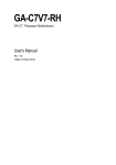
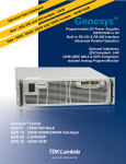
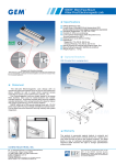
1
Test Report Applicant: Guangdong East Power Co., Ltd. Product: Online High Frequency UPS Trademark: N/A Model No: EA66400, EA6620, EA6640, EA6660, EA6680, EA66100, EA66120, EA66140, EA66160, EA66180, EA66200, EA66220, EA66240, EA66260, EA66280, EA66300, EA66320, EA66340, EA66360, EA66380. Prepared by: Most Technology Service Co., Limited The safety testing has been performed on the submitted samples and found in compliance with the council LVD directive 2006/95/EC. Most Technology Service Co., Limited No.5, 2nd Langshan Road, North District, Hi-tech Industry Park, Nanshan, Shenzhen, Guangdong, China Phone: 86-755-86026850 Fax: 86-755- 26013350 http:// www.szmost.com Report No.: MTS/GEG/T13050257 Page 1 of 33 Test Report EN 62040-1 Uninterruptible power systems (UPS) – Part 1:General and safety requirements for UPS Report Reference No…………………………...: MTS/GEG/T13050257 Tested by (Name +signature) …………: Grace Gong …………………………………. Approved by (Name +signature) ……..: Yvette Zhou ………………………………….. Date of issue…………………………….: May 30, 2013 Testing laboratory Name …………………………...……....: Most Technology Service Co., Limited Address …………………...........…......: No.5, 2nd Langshan Road, North District, Hi-Tech Industrial park, Nanshan, Shenzhen, Guangdong, China Testing location ..................................: Same as above Applicant Name …………………………...……....: GUANGDONG EAST POWER CO., LTD. Address ……………………………….. : NO.6 NORTHERN INDUSTRY ROAD, SONGSHAN LAKE SCI &TECH INDUSTRY PARK, DONGGUAN, P.R. CHINA Test specification Standard ………………………………...: EN 62040-1: 2008 Procedure deviation …………………...: N/A Non-standard test method …………….: N/A Test item Description ……………………………..: Online High Frequency UPS Trademark ……………………………. : N/A Model/type reference ……………….. : EA66400 Rating …………………………………. : Input: AC 380V, 50Hz, 545A Output: AC 380V, 50Hz, 606A, 400KVA,/320KW Manufacture Battery: DC±240V Manufacturer …………………………. : GUANGDONG EAST POWER CO., LTD. Address ……………………………….. : NO.6 NORTHERN INDUSTRY ROAD, SONGSHAN LAKE SCI &TECH INDUSTRY PARK, DONGGUAN, P.R. CHINA Report No.: MTS/GEG/T13050257 Page 2 of 33 Test item particulars Operation condition …………………………..: Continuous Tested IT power system …………………...…: N/A IT testing, phase-phase voltage (V) ………...: N/A Class of equipment ……………….……….…: Class I Mass of equipment (kg) ..............................: Mention in user manual Mains supply tolerance (%)………………..…: +6%, -10% Protection against ingress of water …………: IP20 Possible test case verdicts: - test case does not apply to the test object: N/A - test object does meet the requirement: P (Pass) - test object does not meet the requirement: F (Fail) General remarks The test results presented in this report relate only to the object tested. This report shall not be reproduced, except in full, without the written approval of the Issuing testing laboratory. "(see appended table)" refers to a table appended to the report. “(see remark #)” refers to a remark appended to the report. “(see Annex #) refers to an annex appended to the report. Throughout this report a comma (point) is used as the decimal separator. General Product information: All models are with same principle, constructional and insulation, just different of rating power, etc. The test model EA66400 is the biggest power of all models. Summary of Testing and Conclusions: The Online High Frequency UPS was tested and complied with the requirements of EN 62040-1:2008. Copy of marking plate: Online High Frequency UPS Model: EA66400 Input: AC 380V, 50Hz, 545A, 3 Output: AC 380V, 50Hz, 606A, 400KVA/320KW Manufacture Battery: DC±240V Date: March, 2013 Guangdong East Power Co., ltd. MADE IN CHINA Report No.: MTS/GEG/T13050257 Page 3 of 33 EN 62040-1 Clause Requirement – Test Result - Remark Verdict 4 GENERAL CONDITIONS FOR TESTS P 4.5 Components P Comply either with the requirements of this standard or All components comply with with the safety aspects of the relevant IEC component the requirements of the standard or with the safety standard aspects of the relevant IEC component standards See table 4.5 List of critical components Evaluation and testing of components Components, Which are 1.5.2/RD certified to IEC and/or national standards, are applied correctly within their ratings. Components not covered by IEC standards are tested under the conditions present in the equipment. Thermal controls Thermal controls used are 1.5.3/RD suitable for their intended application and particularly Annex K. Transformers Transformers used are suitable 1.5.4/RD for their intended application and comply with the relevant requirements of the standard and particularly Annex C Interconnecting cables For external battery cabinet 1.5.5/RD only Capacitors in primary circuits: Between lines: X2 capacitor 1.5.6/RD according to IEC 6038414:1993 with 21 days damp heat test. Between line/neutral and PE: Y2 capacitor according to IEC 60384-14:1993. Double insulation or reinforced insulation bridged by See below. 1.5.7/RD components 1.5.7.1/RD General See below. No bridging capacitors 1.5.7.2/RD Bridging capacitors provided. 1.5.7.3/RD Bridging resistors No such resistor 1.5.7.4/RD Accessible parts 1.5.8/RD Components in equipment for IT power systems 4.6 Power interface 1.6.1/RD AC power distribution systems Report No.: MTS/GEG/T13050257 Backfeed protection in compliance with requirements of limited current circuits. Further details see sub clause 2.4. Not applied for IT power systems. P P P P P P P P N/A N/A P N/A P TN power system. P Page 4 of 33 EN 62040-1 Clause Requirement – Test Result - Remark 1.6.2/RD 1.6.4/RD Input current See table 4.6 P Neutral conductor Basic insulation for rated voltage between earthed parts and line and neutral conductors. O/p neutral is not isolated from the i/p neutral. P 4.7 Marking and instructions 4.7.1 General 4.7.2 Power rating Verdict P P All required markings are affixed on labels located on the front enclosure of UPS Input rated voltage/range (V) ..................................... : See page 4 Input rated current/range (A)...................................... : See page 4 P P P Input symbol for nature of supply (d.c.) ..................... : Not designed for "d.c. only". Therefore, no such marking required. Input rated frequency/range (Hz) ............................... : See page 4 N/A P Output rated voltage/range (V) .................................. : See page 4 Output rated current/range (A) ................................... : See page 4 P Number of output phases (1- 3) with/without neutral : UPS: 3with neutral P Output rated active power (W) ................................... : P P See page 4 Output rated apparent power (VA) ............................. : See page 4 Output symbol for nature of supply (d.c.) .................... : No d.c. output. Therefore, no such marking required. Rated frequency or rated frequency range (Hz)……….: See page 4 Max. ambient operating temperature range (C)…….. : 0℃-40℃ Manufacturer’s name or trademark or Guangdong East Power Co., identification mark ..................................................... : ltd. Type/model or type reference .................................... : See page 4 Symbol for Class II equipment only ........................... : Class I equipment Other symbols ........................................................... : Additional symbols or markings do not give rise to misunderstanding. Certification marks .................................................... : CE P N/A P P P P N/A P P Instructions for units with automatic See user manual bypass/maintenance bypass, additional input a.c. supply, or external batteries, having text "See installation instructions before connecting to the supply" ............................................................ : P 4.7.3 Safety instructions See below. P 4.7.3.1 General See below. P Report No.: MTS/GEG/T13050257 Page 5 of 33 EN 62040-1 Clause Requirement – Test Result - Remark Verdict Safety instructions available as required to avoid introduction of hazards when operating, installing, maintaining, transporting or storing the UPS. User manual inform adequate information to users and there are such words in user manuals 4.7.3.2 Installation 4.7.3.3 Guidance on the level of competence necessary for User manual inform adequate installation for operator and service person ...............: information to users and there are such words in user manuals Installation instructions should include reference to national wiring rules. Operation Guidance on the level of competence necessary to operate the equipment. 4.7.3.4 Maintenance 4.7.3.5 Safety instructions to be used during maintenance of the UPS are normally made available only to service persons. Distribution related backfeed P User manual inform adequate information to users and there are such words in user manuals P No mains voltage adjustment device Supply voltage adjustment .........................................: No adjustment. Methods and means of adjustment; reference to installation instructions ...............................................: Power outlets .............................................................: The maximum apparent and active power of the standard outlet is indicated on the rating plate. Fuse identification (marking, special fusing There is a marking located characteristics, cross-reference) .................................: adjacent to each fuse to indicate the specification of the fuse Wiring terminals See below. 1.7.7.1/RD Protective earthing and bonding terminals ...................: The protective earthing wiring terminal is indicated by the symbol (IEC60417) 1.7.7.2/RD Terminal for a.c. mains supply conductors .................: Letter ’N’ used Report No.: MTS/GEG/T13050257 P P 1.7.4/RD 1.7.7.3/RD Terminals for d.c. mains supply conductors ……….....: P P Main voltage adjustment ............................................: 4.7.7 1.7.7/RD P P 4.7.4 4.7.6 1.7.6/RD P P For the purpose of warning the electrical service person against backfeed situations not caused by the UPS but that may arise when a particular load fault is present while the UPS operates in stored energy mode or while unbalanced loads are supplied through a particular power distribution system, the installation instructions for permanently connected UPS shall require the fitting of a warning label Warning label with text "Before working on this circuit, -Isolate Uninterruptible Power System (UPS) -Then check for Hazardous Voltage between all terminals including the protective earth. Risk of Voltage Backfeed 4.7.5 1.7.5/RD P N/A N/A N/A P P P P P N/A Page 6 of 33 EN 62040-1 Clause Requirement – Test 4.7.8 4.7.9 1.7.8/RD Battery terminals ........................................................: Internal batteries used Controls and indicators Result - Remark Verdict N/A See below. P 1.7.8.1/RD Identification, location and marking .............................: On battery bodys 1.7.8.2/RD Colours ..................................................................... : Colours are acceptable due to only used for information (no safety involved even if disregarded). Symbols according to IEC 60417................................ : 1.7.8.3/RD 1.7.8.4/RD Markings using figures ............................................... : 4.7.10 Isolation of multiple power sources ............................ : 1.7.9/RD IT power systems 4.7.11 1.7.10/RD IT power distribution systems 4.7.12 Protection in building installations 4.7.13 5.1/RD 4.7.14 1.7.11/RD 4.7.15 1.7.12/RD 4.7.16 Durability of markings Removable parts The labels were subjected to the permanence of marking test. The labels were rubbed with cloth soaked with water for 15 s and then again for 15 s with the cloth soaked with petroleum spirit. After this test there was no damage to the labels. The marking on the labels did not fade. There was neither curling nor lifting of the label edges. No removable part in normal operation mode 4.7.18 1.7.13/RD Replaceable batteries - if the battery is placed in an OPERATOR ACCESS AREA, there shall be a marking close to the battery or a statement in both the operating and the servicing instructions; - if the battery is placed elsewhere in the equipment, there shall be a marking close to the battery or a statement in the servicing instructions. Report No.: MTS/GEG/T13050257 P N/A N/A N/A N/A N/A Permanerce connected three-phase UPS, have the protectin in buiding installations and other protection. High leakage current (mA) ............................. : Leakage current of the equipment does not exceed 3.5 mA. Thermostats and other regulating devices No device is intended to be adjusted during in installation or normal operation mode Language(s) ............................................................. : English Language 1.7.11/RD 4.7.17 1.7.12/RD Not used. Only one external supply of hazardous voltage or energy Not applied for IT power systems. P Replaceable by server person. See user manual P N/A N/A P P N/A P N/A P Page 7 of 33 EN 62040-1 Clause Requirement – Test Result - Remark Verdict There is no operator access with a tool in normal operation mode Battery There is a battery warning label in the battery compartment to show the following information --- battery type --- nominal voltage of total battery --- nominal capacity of total battery --- warning label denoting an energy or electrical shock and chemical hazard and reference See label in Annex Photos Clearly legible information ......................................... : Warning label containing below described information placed on enclosure of UPS and battery compartment. Information clearly legible. Battery type ................................................................: Lead acid, type as "12Vdc 7Ah" 4.7.19 Operator access with a tool................................... : 1.7.2.5/RD 4.7.20 Nominal voltage of total battery (V) ……………........: N/A P P P DC±240V Nominal capacity of total battery (optional) …………....: 7Ah P Warning label .............................................................: P P Instructions ...............................................................: P 4.7.21 Installation instructions No special attention is needed 5 FUNDAMENTAL DESIGN REQUIREMENTS P 5.1 Protection against electric shock and energy hazards P 5.1.1 Protection for UPS intended to be used in operator access areas See below. P 2.1.1.2/RD Battery compartments............................................. : 2.1.1.4/RD Access to hazardous voltage circuit wiring 2.1.1.5/RD Energy hazards ................................................ : 2.1.1.6/RD Manual controls Permitted to have access to: - bare parts of SELV circuits - bare parts of limited current circuits - TNV circuits under specified conditions 5.1.2 5.1.3 Protection for UPS intended to be used in service access areas Protection for UPS intended to be used in restricted access areas Report No.: MTS/GEG/T13050257 N/A P No any hazardous voltage circuit wiring can be accessed by operator. There is no energy hazard in operation access areas No conductive controls or handles or alike provided. Operator access to earthing metal enclosure only. TNV circuits can’t accessed by operation, test with probe P P N/A P N/A N/A Page 8 of 33 EN 62040-1 Clause Requirement – Test Result - Remark Verdict Working voltage (Vpeak or Vrms); minimum distance (mm) through insulation 5.1.4 Backfeed protection See appended table 8.2. - Backfeed protection provided Description of the construction ................................... : by the mains relay. P 5.1.5 Emergency switching device P 5.2 Requirements for auxiliary circuits P 5.2.1 Safety extra low voltage circuits – SELV P 2.2.1/RD General requirements P 2.2.2/RD Voltages under normal conditions P 2.2.3/RD Voltages under fault conditions P 2.2.4/RD Connection of SELV circuits to other circuits Use isolate transformer and adequate creepage distance and clearance to provide reinforced insulation between RS232 circuit and hazardous voltage circuits P 5.2.2 Telephone network voltage circuits – TNV N/A 5.2.3 Limited current circuits N/A 2.4.1/RD General requirements See below. N/A 2.4.2/RD Limit values See appended table 5.3. N/A Frequency (Hz) ..........................................................: - Measured current (mA) ...............................................: - Measured voltage (V)..................................................: - Measured capacitance (F) ........................................: - 2.4.3/RD Connection of limited current circuits to other circuits N/A 5.2.4 External signalling circuits N/A 3.5/RD Interconnection of equipment N/A 3.5.1/RD General requirements N/A 3.5.2/RD Types of interconnection circuits N/A 3.5.3/RD ELV circuits as interconnection circuits N/A 3.5.4/RD Data ports for additional equipment N/A 5.2.5 2.5/RD Limited power source For RS-232 USB, RS485 port P a) Inherently limited output N/A b) Impedance limited output P c) Regulating network limited output under normal operating and single fault condition Report No.: MTS/GEG/T13050257 N/A Page 9 of 33 EN 62040-1 Clause Requirement – Test Result - Remark Verdict d) Overcurrent protective device limited output N/A Max. output voltage (V), max. output current (A), max. apparent power (VA) -- Current rating of overcurrent protective device (A) -- 5.3 Protective earthing and bonding P 5.3.1 General See below. P 2.6/RD Provisions for earthing and bonding See below. P 5.3.1 2.6.1/RD Protective earthing UPS are class I equipments, connection of relevant conductive parts to the PE terminal via green/yellow insulated wires. P All eartheing is separated from parts at hazardous voltages P 2.6.2/RD Functional earthing 2.6.3/RD Protective earthing and protective bonding conductors P 2.6.3.1/RD General 2.6.3.2/RD Size of protective earthing conductors P Size of protective earthing conductors comply with the requirements in table 3B/RD P Rated current (A), cross-sectional area (mm2), AWG 2.6.3.3/RD Size of protective bonding conductors Size of protective earthing conductors comply with the requirements in table 3B/RD P Same as 2.6.3.1/RD Rated current (A), cross-sectional area (mm2), AWG 2.6.3.4/RD Resistance (Ω) of earthing conductors and their terminations, resistance (ohm), voltage drop (V), test current (A), duration (min) P Colour of insulation: The insulation of the protective eatthing conductor in power cord supplied with equipment and the protective bonding conductor is green and yellow P Terminals See below. P 2.6.3.5/RD 2.6.4/RD Resistance of the protective bonding conductor is less than 0.1Ω See table 5.3 2.6.3.3/RD Ground continuity Test 2.6.4.1/RD General P 2.6.4.2/RD Protective earthing and bonding terminals P Rated current (A), type, nominal thread diameter (mm) Separation of the protective earthing conductor from protective bonding conductors P Integrity of protective earthing See below. P 2.6.4.3/RD 2.6.5/RD The earthing terminal in the appliance inlet is regarded as the main protective earthing terminal Separate wiring terminals are provided to protective earthing conductor and protective bonding conductor Report No.: MTS/GEG/T13050257 Page 10 of 33 EN 62040-1 Clause Requirement – Test Result - Remark Interconnection of equipment This unit has it's own earthing connection. PE terminals of outlets reliably connected to PE terminal of unit 2.6.5.1/RD Verdict 2.6.5.2/RD Components in protective earthing conductors and protective bonding conductors P P 2.6.5.3/RD Disconnection of protective earth N/A 2.6.5.4/RD Parts that can be removed by an operator N/A 2.6.5.5/RD Parts removed during servicing 2.6.5.6/RD Corrosion resistance 2.6.5.7/RD Screws for protective bonding 2.6.5.8/RD Reliance on telecommunication network or cable distribution system 5.3.2 Protective earthing The relevant potential hazard is removed at the same time when protective earthing connection is disconnected for servicing All safety earthing connections in compliance with Annex J. P P Self-tapping screws are used to provided protective bonding connection and is threaded into more than twice the pitch of the screw thread P Protective earthing does not rely on a TNV circuit N/A P 5.3.3 Protective bonding P 5.4 P 5.4.1 AC and d.c. power isolation General 3.4/RD Disconnection from the mains supply P 3.4.1/RD General requirement See below. P 3.4.2/RD Disconnect devices Permanently connected equipment P 3.4.3/RD Permanently connected equipment 3.4.4/RD Parts which remain energized 3.4.5/RD Switches in flexible cords 3.4.6/RD Number of poles-single-phase and d.c. equipment 3.4.7/RD Number of poles- three-phase equipment P 3.4.8/RD Switches as disconnect devices P 3.4.9/RD Plugs as disconnect devices 3.4.10/RD Interconnected equipment 3.4.11/RD Multiple power sources Report No.: MTS/GEG/T13050257 P P N/A No switchs in the flexible cords N/A N/A Permanence connected equipment, no plugs used N/A N/A UPS under test receives power from an AC 380V power source N/A Page 11 of 33 EN 62040-1 Clause Requirement – Test Result - Remark Verdict 5.4.2 Disconnect devices Ungrounded battery, the internal battery DC supply of the UPS can be disconnected by the quick connectors of the battery P 5.5 Overcurrent and earth fault protection P 5.5.1 General P 2.7.3/RD Short-circuit backup protection 2.7.4/RD 2.7.5/RD Building installation is considered as providing. shortcircuit backup protection. Number and location of protective devices ................. : Over current protection by the Input breaker in equipment Protection devices considered to provide sufficient protection against earth faults. Protection by several devices P P P P 5.5.3 Warning to service personnel ..................................... : See user manual Basic requirements Equipment relies on circuit breaker in the equipment in regard to L to N short-circuit. Over current protection is provided by the built-in circuit breaker. Battery circuit protection See below 5.5.3.1 Overcurrent and earth fault protection P 5.5.3.2 Location of protective device 2.7.6/RD 5.5.2 Battery supplies are protected by fuses located adjacent to the batteries before any components which may fail short-circuited, such as capacitors, semi-conductor P P P 5.5.3.3 Rating of protective device 5.3.1/RD Protection against overload and abnormal operation 5.6 Protection of personnel – Safety interlocks N/A 5.6.1 Operator protection N/A 2.8/RD Safety interlocks N/A 2.8.1/RD General principles N/A 2.8.2/RD Protection requirements N/A 2.8.3/RD Inadvertent reactivation N/A 2.8.4/RD Fail-safe operation N/A 2.8.5/RD Moving parts N/A Report No.: MTS/GEG/T13050257 See table4.3. No hazards P P Page 12 of 33 EN 62040-1 Clause Requirement – Test Result - Remark Verdict 2.8.6/RD Overriding N/A 2.8.7/RD Switches and relays N/A 2.8.7.1/RD Contact gaps (mm) .................................................... : Mechanical actuators 2.8.8/RD N/A 2.8.7.2/RD Overload test N/A 2.8.7.3/RD Endurance test N/A 2.8.7.4/RD Electric strength test N/A 5.6.2 Service person protection N/A There is no service person access areas while EUT is energized. N/A 5.6.2.1 Introduction N/A 5.6.2.2 Covers N/A 5.6.2.3 Location and guarding of parts N/A 5.6.2.4 Parts on doors N/A 5.6.2.5 Component access N/A 2.8.3/RD Inadvertent reactivation N/A 5.6.2.6 Moving parts N/A 5.6.2.7 Capacitor banks N/A 5.6.2.8 Internal batteries. N/A 5.7 2.10/RD Clearances, creepage distances and distances through insulation 2.10.1/RD General 2.10.2/RD Determination of working voltage 2.10.3/RD Clearances 2.10.3.1/R General D 2.10.3.2/R Clearances in primary circuits D 2.10.3.3/R Clearances in secondary circuits D P Adopt the condition-Pollution Degree 2 Unit was connected to AC 380V(maximum) TN power system. See appended table 8.2 See below, Annex G was not considered. Annex F/RD and minimum clearances considered. Clearance in primary circuits meet the requirement Clearance in secondary circuits meet the requirement 2.10.3.4/R Measurement of transient voltage levels D 2.10.4/RD P P P P P P N/A Creepage distances Cree-page distance meets the requirement P CTI tests........................................................... : CTI rating for all materials of min. 100. - Report No.: MTS/GEG/T13050257 Page 13 of 33 EN 62040-1 Clause Requirement – Test Result - Remark 2.10.5/RD Solid insulation See below. 2.10.5.1/R Minimum distance through insulation D 2.10.5.2/R Thin sheet material D Verdict P See appended table. P Transformer insulation sheet and mylar sheet used Number of layers (pcs)................................................ : Three for transformer insulation, and one layer for my lar sheet. Electric strength test 3000V 2.10.5.3/R Printed boards D P Distance through insulation P Electric strength test for thin sheet insulating material - Number of layers (pcs)............................................... : - 2.10.5.4/R Wound components D Number of layers (pcs)............................................... : 2.10.6/RD P N/A N/A Two wires in contact inside wound component; angle between 45and 90........................................ : N/A Coated printed boards N/A 2.10.6.1/R General D N/A 2.10.6.2/R Sample preparation and preliminary inspection D N/A 2.10.6.3/R Thermal cycling D N/A 2.10.6.4/R Thermal ageing (C)................................................... : D N/A 2.10.6.5/R Electric strength test D - 2.10.6.6/R Abrasion resistance test D N/A Electric strength test 2.10.7/RD 2.10.8/RD 2.10.9/RD - Enclosed and sealed parts.......................................... : N/A Temperature T1=T2 + Tma – Tamb +10K (C) ………….... : Spacings filled by insulating compound ..................... : Certified sources of Photo-coupler used. No other components applied for. Electric strength test Electric strength test was performed during the component approval. Component external terminations N/A Report No.: MTS/GEG/T13050257 P P Page 14 of 33 EN 62040-1 Clause Requirement – Test Result - Remark 2.10.10/R D Insulation with varying dimensions No reduction of distances considered. 6 WIRING, CONNECTIONS AND SUPPLY P 6.1 General Introduction P 6.1.1 Verdict N/A P 3.1/RD 3.1.1/RD Current rating and overcurrent protection 3.1.2/RD Protection against mechanical damage 3.1.3/RD Securing of internal wiring 3.1.4/RD Insulation of conductors 3.1.5/RD Beads and ceramic insulators 3.1.6/RD Screws for electrical contact pressure 3.1.7/RD Insulating materials in electrical connections 3.1.8/RD Self-tapping and spaced thread screws All wirings meet the requirement P Wires do not touch sharp edges and heatsinks, which could damage the insulation and cause hazard. Internal wirings are routed, supported, clamped, secured in place P P P Not used. All screws for electrical contact pressure are threaded into more than two complete threads There is not non-metallic material to be used in electrical connections in EUT No self- tapping or spaced thread screws used for connection of current-carrying parts. N/A P N/A N/A 10 N pull test Test performed and passed. P 3.1.9/RD Termination of conductors 3.1.10/RD Sleeving on wiring 6.1.2 6.2 Dimensions and ratings of busbars and insulated conductors Connection to power 6.2.1 General provisions for connection to power 3.2.2/RD Multiple supply connections 3.2.3/RD Permanently connected equipment 3.2.4/RD Number of conductors, diameter (mm) of cable and conduits .............................................................: Appliance inlets Report No.: MTS/GEG/T13050257 Use soldered, welded and similar terminations for the connection of conductors P Heat shrinkable tube reliable fix on the wiring P P P P Single supply connection N/A P See table 4.3 N/A Page 15 of 33 EN 62040-1 Clause Requirement – Test Result - Remark 3.2.5/RD Power supply cords See below Verdict P 3.2.5.1/RD AC power supply cords See appended table Type .......................................................................... : P - Rated current (A), cross-sectional area (mm2), See table 4.3 AWG ..........................................................................: 3.2.5.2/RD DC power supply cords Cord anchorages and strain relief 3.2.6/RD N/A P 3.2.7/RD Protection against mechanical damage 3.2.8/RD Cord guards P D (mm); test mass (g) ................................................ : - Radius of curvature of cord (mm) .............................. : Means of connection ................................................. : Wire terminals - 6.2.2 No parts under this unit likely to damage the power supply cord. Enclosure without sharp edges. P More than one supply connection .............................. : Only one supply connection provided. 6.3 Wiring terminals for external power conductors 3.3.1/RD Wiring terminals P N/A P permanently connected equipments provided with terminals in which connection is made by means of screws and nuts P 3.3.2/RD Connection of non-detachable power supply cords P 3.3.3/RD Screw terminals P 3.3.4/RD Conductor sizes to be connected 3.3.5/RD Rated current (A), cord/cable type, crosssectional area (mm2)................................................................. : Wiring terminal sizes 3.3.6/RD Rated current (A), type and nominal thread diameter (mm) .......................................................... : Wiring terminals design P 3.3.7/RD Grouping of wiring terminals P 3.3.8/RD Stranded wire 7 PHYSICAL REQUIREMENTS 7.1 Enclosure 7.2 Stability 4.1/RD Angle of 10 Test: force (N) .................................................. : Report No.: MTS/GEG/T13050257 N/A P - N/A P The frame or chassis of EUT is not use to carry current during intended operation P See below. The unit does not overbalance Tilted to an angle of 10 P 232*20%=46.4N P P Page 16 of 33 EN 62040-1 Clause Requirement – Test 7.3 Mechanical strength 4.2.1/RD General 4.2.2/RD Steady force test, 10 N 4.2.3/RD Steady force test, 30 N 4.2.4/RD Steady force test, 250 N 4.2.5/RD Impact test Fall test Swing test 4.2.6/RD Drop test 4.2.7/RD Stress relief test Test 4.2.8/RD Cathode ray tubes Result - Remark Verdict P Tests performed and passed. Results see below. After tests, unit complied with the requirements of sub-clauses 2.1.1/RD, 2.6.1/RD and 2.10/RD. 10 N applied to all components other than enclosure. P P 30N, 5S to door 250 N applied to outer enclosure. P See Below No hazard as result from steel ball fall test. No hazard as result from steel ball swing test. P P Not required for this equipment. performed at 70°C no distortion found on front panel. No CRT in the unit. P P N/A P N/A Picture tube separately certified.................................. : N/A 4.2.9/RD High pressure lamps No high pressure lamp provided. N/A 4.2.10/RD Wall or ceiling mounted equipment; force (N) . : N/A 7.4 Construction details P 7.4.1 Introduction P 4.3.1/RD Edges and corners 4.3.2/RD 4.3.3/RD 4.3.4/RD All edges and corners are rounded and smoothed No handles or manual controls Handles and manual controls; force (N) ..................... : provided. No axial pull applied to push-buttons. There is not such adjustable Adjustable controls control device in EUT There is not such part of Securing of parts securing in EUT P N/A N/A P 4.3.5/RD Connection of plugs and sockets 4.3.7/RD Heating elements in earthed equipment No heating elements provided. N/A 4.3.11/RD Containers for liquids or gases No container for liquids or gases provided. N/A 4.4/RD Protection against hazardous moving part 4.4.1/RD General 4.4.2/RD Protection in operator access areas N/A 4.4.3/RD Protection in restricted access locations N/A 4.4.4/RD Protection in service access areas N/A Report No.: MTS/GEG/T13050257 N/A N/A No such moving part used. N/A Page 17 of 33 EN 62040-1 Clause Requirement – Test Result - Remark Verdict 4.5/RD Thermal requirements 4.5.1/RD General 4.5.2/RD Temperature tests P Normal load condition per Annex L -- P See table 7.7 for details. P 4.5.3/RD Temperature limits for materials See Table 7.7 for details. P 4.5.4/RD Touch temperature limits See Table 7.7 for details. P 4.5.5/RD Resistance to normal heat P 7.4.2 Openings (see appended table 7.7) EUT are equipped with DC fan to vented. No arcing component is adjacent to batteries 7.4.3 Gas concentration 7.4.4 Equipment movement 7.5 4.7/RD 4.7.1/RD 4.7.2/RD N/A No castors provided. N/A Resistance to fire Reducing the risk of ignition and spread of flame Method 1, selection and application of components wiring and materials Method 2, application of all of simulated fault condition tests Conditions for a fire enclosure 4.7.2.1/RD Parts requiring a fire enclosure P P See below. P Use of materials with the required flammability classes. P N/A See below. With having the following components: Components in primary circuits P P Insulated wiring The fire enclosure is required. 4.7.2.2/RD Parts not requiring a fire enclosure Materials 4.7.3/RD 4.7.3.1/RD General 4.7.3.2/RD Materials for fire enclosures N/A P PCB rated accordingly. For details see table 4.3. Metal enclosure with thermoplastic front panel. For details see table 4.3. P P 4.7.3.3/RD Materials for components and other parts outside fire enclosures 4.7.3.4/RD Materials for components and other parts inside fire enclosures See subclause 4.7.2/RD. 4.7.3.5/RD Materials for air filter assemblies No air filters provided. N/A 4.7.3.6/RD Materials used in high-voltage components No high voltage components provided. N/A Report No.: MTS/GEG/T13050257 N/A Internal components except small parts are V-2, HF-2 or better. Batteries have a flammability class of HB (or better). P Page 18 of 33 EN 62040-1 Clause Requirement – Test 7.6 Battery location 7.6.1 Battery location and installation 7.6.2 Accessibility and maintainability 7.6.3 Distance 7.6.4 Case insulation P 5.2/RD Electric strength P 5.2.1/RD General P 5.2.2/RD P 7.6.5 Test procedure Wiring 7.6.6 Electrolyte spillage 7.6.7 Ventilation 7.6.8 Charging voltages 7.7 Temperature rise Maximum temperatures Result - Remark Verdict P Separate battery rooms P P The batteries are fixed in place and the temperature of mounting parts meet requirement of less than 45 degree temperature rise Contact, connections and wiring are protected against effects of ambient tem., moisture, gas, vapour and mechanical stress. EUT are equipped with VRLA type batteries. EUT are equipped with DC fan to vented. No arcing component is adjacent to batteries No hazards P P N/A P P P No excessive temperatures P 4.5/RD Thermal requirements P 4.5.1/RD General 4.5.2/RD Temperature tests P Normal load condition per Annex L -- See table 7.7 for details. P 4.5.3/RD Temperature limits for materials See Table 7.7 for details. P 4.5.4/RD Touch temperature limits See Table 7.7 for details. P 4.5.5/RD Resistance to normal heat See Table 7.7 for details. P 8 8.1 5.1.1/RD ELECTRICAL REQUIREMENTS AND SIMULATED ABNORMAL CONDITIONS P General provisions for earth leakage P Earth leakage current 5.1.2/RD Equipment under test (EUT) 5.1.7/RD Equipment with touch current exceeding 3.5 mA : Report No.: MTS/GEG/T13050257 See subclause 5.1.2/RD below. Only one AC main supply P Touch current of the equipment does not exceed 3.5 mA. P P Page 19 of 33 EN 62040-1 Clause Requirement – Test 8.2 Electric strength 5.2.1/RD General See appended table 8.2. P 5.2.2/RD Test procedure See appended table 8.2. P 8.3 Abnormal operating and fault conditions P 8.3.1 General P 5.3.1/RD No hazards P 5.3.2/RD Protection against overload and abnormal operation Motors DC fan are blocked off P 5.3.3/RD Transformers See appended Annex C. P 5.3.4/RD Functional insulation ................................................ : EUT meet the requirement P 5.3.5/RD Electromechanical components No electromechanical component (except for approved relays) provided. N/A 5.3.9/RD Compliance criteria for abnormal operating and fault conditions 5.3.9.1/RD During the tests 5.3.9.2/RD After the tests Result - Remark Verdict P P ---No fire accurs ---EUT do not emit molten metal ---Enclosures do not deform After all abnormal test ---reinforced and basic insulation does show visible signs of damage ---the clearance and creepage distance do not reduce below the value specified in 2.10/RD P P 8.3.2 Simulation of faults No hazards P 8.3.3 Conditions for tests No hazards P 9 CONNECTION TO TELECOMMUNICATION NETWORKS P 6.1/RD Protection of telecommunication network service persons, and users of other equipment connected to the network, from hazards in the equipment Protection from hazardous voltages P 6.1.1/RD Separation of the telecommunication network from 6.1.2/RD earth 6.1.2.1/RD Requirements Test voltage (V) ......................................................... : 3kV Current in the test circuit (mA) ................................... : Not exceed 10mA 6.1.2.2/RD Exclusions ................................................................. : Protection of equipment users from overvoltages on telecommunication networks 6.2/RD 6.2.1/RD Separation requirements Report No.: MTS/GEG/T13050257 P P P N/A P P Page 20 of 33 EN 62040-1 Clause Requirement – Test 6.2.2/RD Electric strength test procedure Result - Remark Verdict P 6.2.2.1/RD Impulse test 6.2.2.2/RD Steady-state test P 6.2.2.3/RD Compliance criteria Protection of the telecommunication wiring system 6.3/RD from overheating Max. output current (A) .............................................. : P P N/A - Current limiting method.............................................. : - 2.1.3/RD Protection in restricted access locations 2.3/RD TNV circuits P 2.3.1/RD Limits P Type of TNV circuits................................................... : - Separation from other circuits and from accessible parts P Insulation employed .................................................. : Separation from hazardous voltages P Insulation employed ................................................... : 2.3.2/RD 2.3.3/RD 2.3.4/RD The unit is not limited to be used in restricted access locations. Connection of TNV circuits to other circuits Insulation employed .................................................. : 2.3.5/RD Test for operating voltages generated externally 2.6.5.8/RD Reliance on telecommunication network or cable distribution system 2.10.3.3/R Clearances in secondary circuits D N/A N/A N/A P P 2.10.3.4/R D Measurement of transient voltage levels 2.10.4/RD Creepage distances 3.5/RD Interconnection of equipment N/A 3.5.1/RD General requirements N/A 3.5.2/RD Types of interconnection circuits....................... : N/A P CRITERIA FOR TELEPHONE RINGING SIGNALS (see 2.3.1/RD) M/RD ANNEX M, Introduction M.1/RD P P P M.2 /RD Method A P M.3/RD Method B N/A M.3.1/RD Ringing signal P M.3.1.1/R Frequency (Hz) ......................................................... : <70Hz Report No.: MTS/GEG/T13050257 Page 21 of 33 EN 62040-1 Clause Requirement – Test Result - Remark Verdict D M.3.1.2/R D Voltage (V) ............................................................... : <300V M.3.1.3/R D Cadence; time (s), voltage (V) .................................. : 8s, Not exceed 56.5V M.3.1.4/R D Single fault current (mA) .......................................... : M.3.2/RD Tripping device and monitoring voltage ................... : P M.3.2.1/R D Conditions for use of a tripping device or a monitoring voltage P M.3.2.2/R D Tripping device M.3.2.3/R D Monitoring voltage (V) .............................................. : Not exceed 56.5V A/RD ANNEX A, TESTS FOR RESISTANCE TO HEAT AND FIRE A.1/RD Flammability test for fire enclosures of movable Metal enclosure equipment having a total mass exceeding 18kg, and of stationary equipment (see 4.7.3.2) A.1.1/RD Not exceed 56.5mA P - N/A N/A Samples …………………………….……………………: - Wall thickness (mm) ……………………………………: - A.1.2/RD Conditioning of samples; temperature (℃) …………..: N/A A.1.3/RD Mounting of samples ……………………………………: N/A A.1.4/RD Test flame (see IEC 60695-11-3) N/A Flame A, B, C or D ………………………………………: A.1.6/RD A.2/RD A.2.1/RD A.2.2/RD - Test procedure N/A Compliance criteria N/A Sample 1 burning time (s) ……………………………..: - Sample 2 burning time (s) ……………………………..: - Sample 3 burning time (s) ……………………………...: - Flammability test for fire enclosures of movable equipment having a total mass not exceeding 18kg, and for material and components located inside fire enclosures (see 4.7.3.2 and 4.7.3.4) N/A Samples, material ………………………………………: - Wall thinkness (mm) - Conditioning of samples Report No.: MTS/GEG/T13050257 N/A Page 22 of 33 EN 62040-1 Clause Requirement – Test Result - Remark A.2.3/RD Mounting of samples N/A A.2.4/RD Test flame (see IEC 60695-11-4) N/A Flame A, B or C …………………………………………: Verdict - A.2.5/RD Test procefure N/A A.2.6/RD Compliance criteria N/A A.2.7/RD Sample 1 burning time (s) ……………………………..: - Sample 2 burning time (s) ……………………………..: - Sample 3 burning time (s) ……………………………..: Alternative test acc. to IEC 60695-2-2, cl. 4 and 8 N/A Sample 1 burning time (s) ……………………………..: - Sample 2 burning time (s) ……………………………..: - Sample 3 burning time (s) ……………………………..: - A.3/RD Hot flaming oil test (see 4.6.2) N/A A.3.1/RD Mounting of samples N/A A.3.2/RD Test procedure N/A A.3.3/RD Compliance criterion N/A B/RD ANNEX B, MOTOR TESTS UNDER ABNORMAL CONDITIONS (see 4.7.2.2/RD and 5.3.2/RD) B.1/RD General requirements d.c. fan motors in SECONDARY CIRCUITS P Position …………………………………………………: Rear of the enclosure - Manufacturer ……………………………………………: See table 4.3 - Type ……………………………………………………..: See table 4.3 - Rated values ……………………………………………: See table 4.3 - B.2/RD Test conditions The test in the equipment P B.3/RD Maximum temperatures No excessive temperatures P B.4/RD Running overload test N/A B.5/RD Locked-rotor overload test N/A P Test duration (days) …………………………………….: - Electric strength test: test voltage (V) …………………: - B.6/RD Running overload test for d.c. motors in secondary circuits B.6.1/RD General N/A B.6.2/RD Test procedure N/A B.6.3/RD Alternative test procedure N/A Report No.: MTS/GEG/T13050257 No possible N/A Page 23 of 33 EN 62040-1 Clause Requirement – Test Result - Remark Verdict B.6.4/RD Electric strength test B.7/RD Locked-rotor overload test for d.c. motors in secondary circuits P B.7.1/RD General P B.7.2/RD Test procedure B.7.3/RD Alternative test procedure; test time (h) ………………: Temp. not exceed the values specified in Table B.1. after test 2h until steady conditions are established N/A Block until steady conditions are established P B.7.4/RD Electric strength test B.8/RD Test for motors with capacitors N/A B.9/RD Test for three-phase motors N/A B.10/RD Test for series motors N/A C/RD Operation voltage Not exceed 60 V d.c P N/A Operating voltage (V) …………………………………..: - ANNEX C, TRANSFORMERS (see 1.5.4/RD and 5.3.3/RD) P Position ………………………………………….………..: See table 4.3 - Manufacturer ………………………..……………………: - Type ………………………………………..……………..: - Rated values …………………………………….………: - Method of protection ……………………….……………: - C.1/RD Overload test C.2/RD Insulation No excessive temperature P P Protection from displacement of windings ……………: N/A Safety isolation transformer P With AC 3000V after humidity treatment Result - D/RD ANNEX D, MEASURING INSTRUMENTS FOR TOUCH-CURRENT TESTS (see 5.1.4/RD) P D.1/RD Measuring instrument P D.2/RD Alternative measuring instrument E/RD TEMPERATURE RISE OF A WINDING (see 1.4.13) Thermocouple method used Report No.: MTS/GEG/T13050257 Not used N/A N/A Page 24 of 33 EN 62040-1 Clause Requirement – Test F/RD MEASURING OF CLEARANCES AND CREEPAGE DISTANCES (see 2.10) G/RD ANNEX G, ALTERNATIVE METHOD FOR DETERMINING MINIMUM CLEARANCES N/A G.1/RD General N/A G.1.1/RD General N/A G.1.2/RD Summary of the procedure for determining minimum clearances N/A G.2/RD Determination of mains transient voltage (V) ………..: N/A G.2.1/RD AC mains supply N/A G.2.2/RD Earthed d.c. mains supplies N/A G.2.3/RD Unearthed d.c. mains supplies N/A G.2.4/RD Battery operation N/A G.3/RD Determination of telecommunication network transient voltage (V) ………………………………………………: N/A G.4/RD Determination of required withstand voltage (V) ……..: N/A G.4.1/RD Mains transients and internal repetitive peaks N/A G.4.2/RD Transients from telecommunication networks N/A G.4.3/RD Combination of transients N/A G.4.4/RD Transients from cable distribution systems N/A G.5/RD Measurement of transient levels (V) ………………….: N/A G.6/RD Determination of minimum clearances ……………….: N/A H/RD ANNEX H, GUIDANCE ON PROTECTION AGAINST INGRESS OF WATER AND FOREIGN OBJECTS (see IEC 60529) N/A J/RD ANNEX J, TABLE OF ELECTROCHEMICAL POTENTIALS (see 2.6.5.6/RD) P Metal used ………………………………………………: Result - Remark Verdict P Screw: steel plated with Zn; Enclosure: mild metal Nut and washer: steel plated with Zn The max electrochemical potential is :0. 3V for metal with Zn - K/RD ANNEX K, THERMAL CONTROLS (see 1.5.3 and 5.3.7) N/A K.1/RD Marking and breaking capacity N/A K.2/RD Thermostat reliability; operating voltage (V) …………: N/A Report No.: MTS/GEG/T13050257 Page 25 of 33 EN 62040-1 Clause Requirement – Test K.3/RD Thermostat endurance test; operating voltage (V) ….: N/A K.4/RD Temperature limiter endurance; operating voltage (V) : N/A K.5/RD Thermal cut-out reliability N/A K.6/RD Stability of operation N/A L ANNEX L, BACKFEED PROTECTION TEST L.1 General See L.2 below. L.2 Test for pluggable equipment type A or pluggable equipment type B UPS No pluggable equipment L.3 Test for permanently connected UPS L.4 Single-fault conditions M ANNEX M, EXAMPLES OF REFERENCE LOAD CONDITIONS P M.1 General P M.2 Reference resistive load N/A M.3 Reference inductive-resistive load N/A M.4 Reference capacitive-resistive loads Result - Remark Verdict P P N/A P No hazards P See below. Worst-case power factors as specified by the manufacturer maintained during the relevant tests. P M.5 Reference non-linear load N/A M.5.1 Test method N/A M.5.2 Connection of the non-linear reference load N/A N ANNEX N, VENTILATION OF BATTERY COMPARTMENTS P N.1 General P N.2 Hydrogen concentration N.3 Blocked conditions N.4 Overcharge test U/RD ANNEX U, INSULATED WINDING WIRES FOR USE WITHOUT INTERLEAVED INSULATION (see 2.10.5.4/RD) N/A U.1/RD Wire construction N/A U.2/RD Type tests N/A U.2.1/RD Electric strength N/A Report No.: MTS/GEG/T13050257 See N.1 above. comply with require even if the fan is blocked P No hazards P No such wires used P Page 26 of 33 EN 62040-1 Clause Requirement – Test U.2.2/RD Flexibility and adherence N/A U.2.3/RD Heat shock N/A U.2.4/RD Retention of electric strength after bending N/A U.3/RD Tests during manufacture N/A U.3.1/RD Routine testing N/A U.3.2/RD Sampling tests N/A X ANNEX X, GUIDANCE FOR DISCONNECTION OF BATTERIES DURING SHIPMENT N/A X.1 Applicable products X.2 Battery disconnection N/A X.3 Package labelling/marking N/A X.4 Damage inspection N/A X.5 The importance of safe handling procedures N/A Y/RD ANNEX Y, ULTRAVIOLET LIGHT CONDITIONING TEST (see clause 4.3.13.3/RD) N/A Y.1/RD Test apparatus ………………………………………….: N/A Y.2/RD Mounting of test samples ………………………………: N/A Y.3/RD Carbon-arc light-exposure apparatus …………………: N/A Y.4/RD Xenon-arc light exposure apparatus …………………..: N/A Report No.: MTS/GEG/T13050257 Result - Remark Currently this annex is only informative. Verdict N/A Page 27 of 33 4.3 TABLE: list of critical components and materials Object/Part No. Manufacturer /Trademark P Type/Model Technical Data2) Mark(s) of Conformity1) Wire Shenzhen Jinyangguang Wire & Cable Co., Ltd. 60227 IEC 02(RV) 4mm2 450/750V TUV Alt. Guangzhoushi Qiguang Cables & Wires Co.,Ltd 60227 IEC 02(RV) 4mm2 450/750V TUV Alt. Various 60227 IEC 02(RV) 4mm 450/750V Wire Guangzhoushi Qiguang Cables & Wires Co.,Ltd IEC 02(RV) Alt. Shenzhen Jinyangguang Wire & Cable Co., Ltd. 60227 IEC 02(RV) Alt. Various 60227 IEC 02(RV) Fuse BUSSMANN 170M5412 630A/690V VDE & UL Fuse LITTEL FUSE KLK D30 30A/600V UL E81895 Relay TYCO Electronics 277VAC/30A VDE 40019600 DC fan PELKO MOTORS INC 12V/0.819A VDE & UL IGBT Infineon 1200V/40A CE IGBT IR 900V/28A CE Thyristor IXYS CLA50E120 0HB 1200V/50A CE Thyristor SEMIKRON SK100KQ12 1200V/101A CE IR RHRG75120 1200V/75A CE Shenzhen Su Rong Capacitors MPX 280V 474 K(±10%) VDE 40008924 X -cap. Shenzhen Su Rong Capacitors MPX 280V 0.1uF VDE 40008924 X -cap. Shenzhen Su Rong Capacitors MPX 280VAC/3.3uF VDE 40008924 X -cap. Tenta Electric Industrial Co. Ltd. MEX 275V,2.2uF VDE 119119 Y -cap. Murata Mfg. Co., Ltd. KX 250V,470pF VDE 4002831 Y -cap. Yinan Don's Electronic Component Co., Ltd. MKP 250V,103K VDE 135256 PCB Various Various 130℃, 94V-0 UL Inductor Shenzhen Yuyuan Power Co. Ltd. PFC Chock, PPI226040 Inductor BO LUO DA XIN ELECTRIC CO LTD PFC Chock, PPI226040 800uH± 10%,20HKz 800uH± 10%,20HKz Test with the appliance Test with the appliance Fast Recovery Diode X -cap. Report No.: MTS/GEG/T13050257 T92S7D12-1 2 R9238M12B PCB1-7 IKW40N120 H3 IRG4PF50W PBF 2 95mm2, 70mm2 2 2 4mm , 35mm , 2 25mm ,450/750V 95mm2, 70mm2 4mm2 , 35mm2, 2 25mm ,450/750V 95mm2, 70mm2 4mm2 , 35mm2, 25mm2 ,450/750V TUV TUV TUV TUV Page 28 of 33 Object/Part No. Manufacturer /Trademark Wire Varnish PCB TAI-I ELECTRIC WIRE & CABLE CO LTD HANG CHEUNG PETROCHEMICAL LTD KINGBOARD LAMINATES HOLDINGS LTD Type/Model Technical Data2) Mark(s) of Conformity1) EIW 180℃,94V-0 UL E85640 8562/C 130℃ UL E200154 KB-6150 130℃, 94V-0 UL E123995 Tape JINGJIANG YAHUA PRESSURE SENSITIVE GLUE CO., LTD PZ 130℃,94V-0 UL E165111 Epoxy DONGGUAN EATTO ELECTRONIC MATERIAL CO LTD 3300A/B-1 130℃, V-0 UL E218090 Inductor Shenzhen Yuyuan Power Co. Ltd. INV Chock, PPF226026 620uH±10%, 30A Inductor BO LUO DA XIN ELECTRIC CO LTD PFC Chock, PPI226040 800uH± 10%,20HKz Test with the appliance Test with the appliance -Wire TAI-I ELECTRIC WIRE & CABLE CO LTD EIW 180℃,94V-0 UL E85640 -Spacer KINGBOARD LAMINATES HOLDINGS LTD FR-4 130℃, 94V-0 UL E123995 -Epoxy WINNING HI-TECH CO LTD WK-969A 90℃, V-0 UL E87252 SUZHOU TAIHU ELECTRIC ADVANCED MATERIAL CO LTD JEPULS TECHNOLOGY (SHENZHEN) CO., LTD T-4260(a) 130℃ UL E228349 EA66II IGBT 1KHz DRV Transformer BO LUO DA XIN ELECTRIC CO LTD EA66II SCR DRV 1KHz Transformer BO LUO DA XIN ELECTRIC CO LTD EE33 100W, 1.0mH Test with the appliance Test with the appliance Test with the appliance -Bobbin CHANG CHUN PLASTICS Phenolic T375J 94V-0 UL E59481 -Core KAIYUAN EPC13 KP4 -- -- -Wire TAI-I ELECTRIC WIRE & CABLE CO LTD MW75 130℃,94V-0 UL E85640 -Alt. CHENG WEI INDUSTYR CO LTD 2UEW 130℃,94V-0 UL E227475 -Alt. FENG CHING METAL CORP. 2UEW 130℃,94V-0 UL E172395 -Alt. PACIFIC ELECTRIC WIRE & CABLE CO.,LTD UEW 130℃,94V-0 UL E201757 -Tape JINGJIANG YAHUA PRESSURE SENSITIVE GLUE CO., LTD CT-280 130℃ UL E165111 -Alt. XINYU SHENGDAFENG ELECTRIC MATERIAL CO., LTD SDF-3 12 130℃,94V-0 UL E317896 -Varnish HANG CHEUNG PETROCHEMICAL LTD 130℃ UL E200154 -Alt. YUEYANG GREEN TECHNOLOGY CO., LTD 130℃ UL E303754 -Varnish Transformer Report No.: MTS/GEG/T13050257 8562/C 8562E JX1150Y 8-1N Page 29 of 33 Object/Part No. Manufacturer /Trademark Type/Model Technical Data2) Mark(s) of Conformity1) -Teflon Tube CHANGYUAN ELECTRONICS (SHENZHEN) CO LTD CB-TT 200℃ UL E180908 -Alt. GREAT HOLDING INDUSTRIAL CO., LTD CB-TT-L 200℃ UL E156256 WF 130℃,94V-0 UL E165111 #1350F 130℃,94V-0 UL E17385 #1350F 130℃, 94V-0 UL E17385 -Margin tape -Alt. -Alt. 4.6 EUT JINGJIANG YAHUA PRESSURE SENSITIVE GLUE CO LTD 3M COMPANY ELECTRICAL MARKETS DIV (EMD) 3M COMPANY ELECTRICAL MARKETS DIV (EMD) TABLE: input current test Fuse# P Rated(A) U(V) P(Kw) I(A) I fuse(A) Condition/status EA66400 Input breaker 545 342Vac 171.68 502 502 Normal operation at rated load EA66400 Input breaker 545 380Vac 171.76 452 452 Normal operation at rated load EA66400 Input breaker 545 402.8Vac 171.59 426 426 Normal operation at rated load By AC mains supply Note(s): measure the input currents with full load. (Loaded with empty battery charging and rated output full load) 5.3 2.6.3.4/RD TABLE: Provisions for protective earthing P EUT Location Resistance measured(mΩ) comments EA66400 I/P earth →O/P earth I/P earth →metal enclosure I/P earth →earth on PCB 0.018 0.026 0.026 Tested at 250A/10munites Tested at 250A/10munites Tested at 250A/10munites 7.7 TABLE: maximum temperatures P Test voltage (V) ……….…: - See below t1(℃) ……..………………..: -- - t2(℃) …………………..…..: - -- Maximum temperature T of part/at: T (℃) 342V/ 50Hz T (℃) 402.8V/ 50Hz Allowed Tmax(℃) - - - - Connector 39.2 54.0 38.6 53.5 95 Input wire 38.5 53.3 36.7 51.6 105 Output wire 36.8 51.6 36.3 51.2 105 DC battery connector 32.3 47.1 32.5 47.4 95 DC wire 34.8 49.6 34.8 49.7 105 Report No.: MTS/GEG/T13050257 Page 30 of 33 PCB near fuse 32.6 47.4 32.6 47.5 130 RY1 body 38.2 53.0 39.3 54.2 130 RY4 body 40.4 55.2 42.2 57.1 130 T1 coil 63.1 77.9 64.5 79.4 130-10=120 C10 body 36.2 51.0 36.6 51.5 105 PCB near Q1 body 58.8 73.6 58.5 73.4 130 RY2 near panel 33.3 48.1 34.3 49.2 130 DC fan body 38.2 53.0 38.8 53.7 85 U3 body 33.6 48.4 33.6 48.5 130 Transformer coil(near RS232) 46.8 61.6 43.7 58.6 130-10=120 Panel 29.1 43.9 29.7 44.6 85 Enclosure of Main module 30.3 45.1 29.9 44.8 60 Ambient 25.2 40.0 25.1 40.0 -- Note(s): 1. The temperatures were measured under worst normal mode defined in 1.2.2.1 and as described in 1.2.2.1 and as described in sub-clause 1.6.2 and at voltages as described above. 2. The maximum ambient temperature permitted by the manufacturer’s specification is 40℃ 8.1 TABLE: earth leakage current P EUT Condition L→PE (mA) N→PE (mA) Limit (mA) EA66400 Line mode RS232 to L/N RS485 to L/N USB 2.93 0.001 0.001 0.002 2.92 0.001 0.001 0.002 3.5 0.25 0.25 0.25 5.3,7 and 8.2 Swith on Swith on Swith on Swith on TABLE:electric strength tests,impulse tests and voltage surge tests P Test voltage applied between: Test voltage(V) Breakdown Yes/No Primary to SELV(RS-232) 3000Vac No Primary to SELV(RS485) 3000Vac No Primary to SELV(USB) 3000Vac No Input L/N to front Panel 1500Vac No Input L/N to earth 1500Vac No Output L/N to earth 1500Vac No T1 (Pri-Sec) (main board) 3000Vac No Report No.: MTS/GEG/T13050257 Page 31 of 33 7.5 and 8.3 Component No. TABLE:fault condition tests P Ambient temperature (℃) 25℃ -------- Model/type of power supply See nameplate for details -------- Manufacturer of power supply See nameplate for details -------- Rated markings of power supply See nameplate for details -------- Fault Test voltage Fuse Test time (V) No. Fuse current Result (A) Max. temperature: (main board) TX1 coil: 76.3 ℃ DC Fan Block 402.8 2hours -- -- TX1 coil: 70.3℃ PCB near Q1 body:84.0℃ Ambient: 25.0℃ Recoverble, no hazard. Max. temperature: (main board)TX1 coil: 76.5℃,TX1 coil : 72.3℃ Ventilation Block 402.8 1hours -- -- PCB near Q1 body:106.4℃ Ambient: 24.5℃ After 30nins, display: 41.no output voltage. Max. temperature: (main board) TX1 coil: 86.5 ℃ DC Fan Block DC 240V 2hours (by batteries) -- -- TX1 coil: 80.4℃ PCB near Q1 body:83.0℃ Ambient: 25.0℃ Recoverble, no hazard. Max. temperature: (main board)TX1 coil: 86.5 Ventilation Block DC 240V(by 1hours batteries) ℃,TX1 coil : 82.5℃ -- -- PCB near Q1 body:105.3℃ Ambient: 25.1℃ After 30nins, display: 41.no output voltage. T01 Pin 1-2(main board) s-c 380 4mins -- -- Unit working abnormal, no hazard. T01 Pin 6-7(main board) s-c 380 4mins -- -- Unit working abnormal, no hazard. s-c 380 4mins -- -- Unit working abnormal,, no hazard. s-c 380 5mins -- -- Unit shutdown immediately or T1 (near RS232) Other transformer Report No.: MTS/GEG/T13050257 Page 32 of 33 abnormal,No damaged, no hazards C1 s-c 380 4mins -- -- U1 Pin1-2 U1 Pin3-4 U2 Pin1-2 U2 Pin3-4 s-c s-c s-c s-c 380 380 380 380 4mins 4mins 4mins 4mins ----- ----- Q1 1-2 s-c 380 4mins -- -- Unit working abnormal, nonrecoverable. Unit working abnormal, no hazard. Unit working abnormal, no hazard. Unit working abnormal, no hazard. Unit working abnormal, no hazard. Unit working abnormal, non-recoverable, no hazard Note(s): s-c means short-circuit.o-l means overload.o-c means open-circuit. Report No.: MTS/GEG/T13050257 Page 33 of 33 Appendix 1 Whole views of ‘Online High Frequency UPS’ Model: EA66400 Appendix 2 Whole views of ‘Online High Frequency UPS’ Model: EA66400 Appendix 3 Whole views of ‘Online High Frequency UPS’ Model: EA66400 Appendix 4 Whole views of ‘Online High Frequency UPS’ Model: EA66400 Appendix 5 Internal view of ‘Online High Frequency UPS’ Model: EA66400 Appendix 6 Internal view of ‘Online High Frequency UPS’ Model: EA66400 Appendix 7 Internal view of ‘Online High Frequency UPS’ Model: EA66400 Appendix 8 Internal view of ‘Online High Frequency UPS’ Model: EA66400 Appendix 9 Main module views of ‘Online High Frequency UPS’ Model: EA66400 Appendix 10 Main module inner views of ‘Online High Frequency UPS’ Model: EA66400 ---END OF REPORT---