1
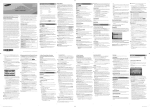
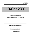
D-Series
1
HEATLESS COMPRESSED AIR DRYER
NDL-060
NDL-070
NDL-080
NDL-090
NDL-100
NDL- 1 1 0
NDL-120
NDL-130
MAINTENANCE & SERVICE MANUAL
www.n-psi.com
GENERAL INFORMATION
Copyright
This manual is copyrighted, all rights reserved. It may not, in whole or in part, be copied, photocopied,
reproduced, translated, or reduced to any electronic medium or machine readable form without prior consent
in writing from nano-purification solutions. It may not be distributed through the internet or computer bulletin
board systems without prior consent from nano-purification solutions.
©2012 nano-purification solutions
Heatless Desiccant Air Dryer: D-Series1 (060-130) Service Manual
Models: NDL-060, 070, 080, 090, 100, 110, 120, 130 (Including ES Model)
Document number: n-psi-D1(060-130)-OM-US-01
Issue: 001
Document Introduction
This manual provides manufacturers prescribed procedures for the maintenance and service procedures for a
nano-purification solutions compressed air dryer. The procedures illustrated in this document are only to be
performed by authorised personnel. For further information regarding the procedures outlined in this document
contact nano-purification solutions before proceeding. Read this document carefully before attempting to
service the dryer.
General Safety
For your own safety, when carrying out maintenance work on the dryer, all relevant national safety regulations
must be complied with relating to pressurised and electrical systems. Only authorised, competent and trained
personnel should maintain the dryer, this user guide is intended solely for such personnel and is to be used
only as a reference, it should not be used to replace conventional training.
CAUTIONS: indicate any situation or operation that may result in potential damage to the
product, injury to the user, or render the product unsafe.
NOTES: highlight important sections of information where particular care and attention should
be paid.
Warranty Guidelines
All dryers are supplied with a 5 year manufacturer’s warranty from the date of purchase. The dryer should be
installed, operated and maintained in accordance with the manufacturer’s guidelines. Only genuine service
parts should be used and no modifications made. For further information please contact us at
support.n-psi.com.
Page 2
MANUFACTURERS DETAILS
nano-purification solutions
11330 Vanstory Blvd
Huntersville, NC 28078
Telephone: (704) 897-2182
Internet:
E-mail:
www.n-psi.com
[email protected]
CONTENTS
Title
Page(s)
4
1.
Service Intervals
2.
Product Assembly
3.
Recommended Tools
7
4.
Dryer Shutdown Procedure
7
5.
Service A Instructions – Cartridge Replacement (NDL-060 – NDL-120)
8
5.1
Service A Instructions – Cartridge Replacement (NDL-130 only)
9
6.
Service B Instructions – Inlet Control & Exhaust Valve Replacement (NDL-060 - NDL-090)
10-11
6.1
Service B Instructions – Inlet Valve Replacement (NDL-100 - NDL-130)
12-13
6.2
Service B Instructions – Inlet Control & Exhaust Valves Replacement (NDL-100 TO NDL-130) 14-15
6.3
Service B Instructions - Outlet Valve Replacement (NDL-060 TO NDL-130)
7.
Service C Instructions – ES Models Only
8.
Re-setting the Dryer Controller
19
9.
Manifold Tightening Sequences
20
10.
Dryer Start-up Procedure
21
11.
Other Dryer Checks & Non-serviceable Items
22
12.
Troubleshooting
23
13.
Service Record & Notes
Page 3
5-6
16
17-18
24-25
1. SERVICE INTERVALS
The following table details the recommended service intervals for this product and the service kits to be used.
Service
Type
A
Recommended Service Intervals
2 Years
(12,000 Hrs)
4 Years
(24,000 Hrs)
P
P
P
B
6 Years
(36,000 Hrs)
P
8 Years
(48,000 Hrs)
P
P
10 Years
(60,000 Hrs)
12 Years
(72,000 Hrs)
P
P
P
Additional For ES Models Only
1
Year
2
Years
3
Years
4
Years
5
Years
6
Years
7
Years
8
Years
9
Years
10
Years
11
Years
12
Years
C
P P P P P P P P P P P P
Dryer
Model
Required Service Kits
Service A
Service B
Service C
NDL-060
NDK-060
NDK-060 + NVK-090
NSK-130
NDL-070
NDK-070
NDK-070 + NVK-090
NSK-130
NDL-080
NDK-080
NDK-080 + NVK-090
NSK-130
NDL-090
NDK-090
NDK-090 + NVK-090
NSK-130
NDL-100
NDK-100
NDK-100 + NVK-130
NSK-130
NDL-110
NDK-110
NDK-110 + NVK-130
NSK-130
NDL-120
NDK-120
NDK-120 + NVK-130
NSK-130
NDL-130
NDK-130
NDK-130 + NVK-130
NSK-130
Page 4
2. PRODUCT ASSEMBLY
MODELS NDL-060 TO NDL-090
TOP COVER
INLET/OUTLET
(TOP) MANIFOLD
ASSEMBLY
DESICCANT
CARTRIDGES
DRYER
COLUMN
DRYER
CONTROLLER
DRYER
SHROUD
BOTTOM
MANIFOLD
ASSEMBLY
SILENCER
BOX
EXHAUST VALVE
INLET VALVE
DRYER LEGS
Page 5
2.1 PRODUCT ASSEMBLY
MODELS NDL-100 TO NDL-130
TOP COVER
OUTLET (TOP)
MANIFOLD
ASSEMBLY
DESICCANT
CARTRIDGES
DRYER
CONTROLLER
DRYER
COLUMN
DRYER
SHROUD
INLET (BOTTOM)
MANIFOLD
ASSEMBLY
SILENCER
BOX
VALVE
BLOCK
INLET
BLOCK
Page 6
EXHAUST VALVE
DRYER LEGS
3. RECOMMENDED TOOLS
The following tools will be required to service the dryer:
TERMINAL SCREW DRIVER
ALLEN KEY 3mm
ALLEN KEY 4mm
ALLEN KEY 6mm
ALLEN KEY 8mm
TORQUE WRENCH (8-60NM)
TORQUE SOCKET 6mm
TORQUE SOCKET 8mm
20mm PIN SPANNER
BEARING PULLER
4. DRYER SHUT DOWN PROCEDURE
Before performing any maintenance or service operations on this product, ensure the product
is isolated from the compressed air supply and fully depressurised. Also ensure the product is
switched off and/or isolated from the mains power.
PROCEDURES
•
Close the inlet and outlet valves.
The dryer might still be pressurised! In order to depressurise the dryer; ensure the dryer is isolated from the
compressed air source:
o
Cycle the dryer twice to ensure the dryer exhausts and is completely depressurised.
o
When fully depressurised the ‘clicking’ of the exhaust valves will be heard but no air
exhausted.
•
Page 7
When the dryer is fully depressurised, isolate from the power supply.
5. SERVICE ‘A’ INSTRUCTIONS
REPLACING DESICCANT CARTRIDGES NDL-060 to NDL-120
(Every 12,000 hrs or 24 months)
Please refer to figure 1
1. Ensure the dryer is shutdown and
fully depressurised before attempting any
maintenance work. (See page 7)
2. Remove the 4x M5 screws as shown to
remove the dryer top cover.
3. Remove the 8x M12 cap head screws and
8x washers to remove the top manifold from
the dryer column.
4x M5 SCREWS
TOP COVER
8x M12 CAP
HEAD SCREWS
4. Discard the gasket seal.
5. Lift the wire handle and remove the
cartridge from the dryer column.
(See figure 2).
TOP MANIFOLD
GASKET SEAL
6. Check and clean the top manifold and dryer
column as required, paying particular attention
to the gasket sealing faces.
7. Remove the new cartridges and gasket
seal from the service kit provided.
DESICCANT CARTRIDGES
8. Insert 2x new desiccant cartridges and
press them down until they stop and the
cartridge is below the top surface of the dryer
column.
9. Insert the new gasket seal placing it into the
gasket groove in the top manifold ensuring it
is fully retained.
Figure 1.
10. Ensure both handles are folded flat.
11. Replace the top manifold and secure with
the 8x M12 cap head screws tightening to a
torque setting of 80Nm.
NOTE: Refer to the page 20 and follow the
correct tightening sequence.
12. The seal between the dryer column and
top manifold should be checked for leaks prior
to fitting the top cover and operating the dryer
13. Replace the dryer top cover and secure
with the 4x M5 screws. These screws should
be hand tightened only or tightened to a
torque setting of less than 1Nm.
If service A is complete reset the dryer, refer
to page 19.
Page 8
Figure 2.
Care must be taken when removing the
desiccant cartridges not to damage the top face
of the dryer column. This is a sealing face!
(Sealing face shown as the shaded area)
5.1 SERVICE ‘A’ INSTRUCTIONS
REPLACING DESICCANT CARTRIDGES (NDL-130 ONLY)
(Every 12,000 hrs or 24 months)
Please refer to Service ‘A’ instructions on page
8 of this service guide.
NOTE: NDL-130 dryer has 2x cartridges per
side. (See Figure 3)
REPLACING DESICCANT CARTRIDGES
DRYER CARTRIDGE
(UPPER)
1. Lift handle and remove the upper cartridges
from the dryer and discard them.
NOTE: Ensure the upper cartridges have
disconnected from the cartridge joining rings
and the lower cartridges before attempting to lift
from the dryer.
2. Remove the lower cartridges from the dryer
and discard.
CARTRIDGE JOINING
RINGS
3. Identify upper and lower cartridges from the
service kit.
4. Insert joining ring into the head of the lower
cartridge.
5. Insert lower cartridges separatey into dryer.
6. Insert upper cartridges separately into dryer.
DRYER CARTRIDGE
(LOWER)
7. See page 8 for reassembling top manifold.
Figure 3
Page 9
6. SERVICE ‘B’ INSTRUCTIONS
REPLACING INLET CONTROL AND EXHAUST VALVES (NDL-060 TO NDL-90)
(Every 24,000 hrs or 4 Years)
1. Ensure the dryer is shutdown
and fully depressurised before
attempting any maintenance work.
(See page 7)
2. Detach each of the solenoid
plugs from the solenoids by
removing the 4x plug screws and
releasing the plugs.
(See Figure 1)
SOLENOID
PLUG
PLUG
SCREW
Figure 1.
RETAINING
CLIP
SOLENOIDS
COILS
Figure 2.
3. Remove the solenoid coils
by unclipping and sliding the
coils from the valve stems.
(See Figure’s 2 & 3)
VALVE
STEM
Figure 3.
Page 10
6. SERVICE ‘B’ INSTRUCTIONS
REPLACING INLET CONTROL AND EXHAUST VALVES (NDL-060 TO NDL-090)
(Every 24,000 hrs or 4 Years)
BOTTOM
MANIFOLD
VALVE
DIAPHRAGM
EXHAUST
VALVE
M5 SOCKET
HEAD SCREWS
Figure 4.
4. Remove the 16x M5 socket head screws and the 16x spring washers and discard them. Remove and
discard the exhaust valve bodies from the bottom manifold. (See Figure 4)
5. Remove and discard the 4x diaphragms from the bottom manifold. (See Figure 4)
6. Replace the 4x diaphragms and 4x exhaust valves from the service kit and replace the 16x M5 socket head
screws and spring washers from the service kit and tighten to a torque setting of 6Nm. (See Figure 4)
NOTE: Refer to the page 20 and follow the correct tightening sequence.
7. Reattach the 4x solenoid coils and 4x solenoid plugs. (See Figure 1)
When service B is complete reset the dryer, refer to page 18.
Page 11
6.1 SERVICE ‘B’ INSTRUCTIONS
REPLACING INLET VALVES NDL-100 TO NDL-130 ONLY
(Every 24,000 hrs or 4 Years)
INLET CONTROL
VALVES
SOLENOID
PLUG
SCREW
Figure 1.
1. Ensure the dryer is shut down
and fully depressurised before
attempting any maintenance
work. (See page 7)
2. Remove the screws and
release the solenoid plugs from
the inlet control valves.
(See Figure 1)
3. Remove the 6x M8 socket
head cap screws and 6x washers
from the inlet block to release
both the valve block and inlet
block from the bottom manifold
and from each other.
(See Figure 2)
4. Remove and discard the 2x
O rings from the inlet block and
replace them from the service kit.
(See Figure 2)
BOTTOM
MANIFOLD
VALVE BLOCK
2x O RINGS
INLET BLOCK
6x M8 HEAD
CAP SCREWS
Figure 2.
Page 12
6.1 SERVICE ‘B’ INSTRUCTIONS
REPLACING INLET VALVES NDL-100 TO NDL-130 ONLY
(Every 24,000 hrs or 4 Years)
VALVE RIDGE
DETAILS
FLOW DIRECTION
ARROW
INLET VALVES
Figure 4.
SPILL PORT
Figure 5.
NOTE: The spill ports are
1.5mmØ holes within the
valve block.
Figure 3.
5. Remove the inlet valves from the valve block by pushing them out. (See Figure 3).
6. Discard the old inlet valves.
7. Insert the new inlet valves into the valve block ensuring the flow direction arrow is pointing as shown and
the valve ridge details cover the spill port. (See Figures 4 & 5)
8. Replace the 6x M8 socket head cap screws and 6x washers and tighten at a torque setting of 20Nm.
(See Figure 2)
9. Reattach the solenoid plugs and the screw to complete the assembly. (See Figure 1)
When service A is complete reset the dryer, refer to page 18.
Page 13
6.2 SERVICE ‘B’ INSTRUCTIONS
REPLACING INLET CONTROL AND EXHAUST VALVES (NDL-100 TO NDL-130)
(Every 24,000 hrs or 4 Years)
VALVE
GASKET
INLET
CONTROL
VALVE
SCREWS
Figure 1.
1. Remove the 6x fixing screws and 6x washers to release the inlet control valves from the valve block.
(See Figure 1)
2. Discard the valve gaskets and inlet control valves and replace from the service pack.
3. Replace the 6x fixing screws and 6x washers.
4. Replace the solenoid plug and screw (See Figure 1 on page 12)
When service B is complete reset the dryer, refer to page 18.
Page 14
6.2 SERVICE ‘B’ INSTRUCTIONS
REPLACING INLET CONTROL AND EXHAUST VALVES (NDL-100 TO NDL-130)
(Every 24,000 hrs or 4 Years)
SILENCER BOX
SILENCER
FIXING
NUT
O RING
Figure 1.
1. Ensure the dryer is shutdown
and fully depressurised before
attempting any maintenance work.
(See page 7)
2. Unscrew the silencer fixing nut
using a 20mm pin spanner and
remove the O ring to release the
silencer box from the assembly.
(See Figure 1)
3. Remove the 8x M5 socket head
screws and the 8x spring washers
and remove the exhaust valve
bodies and diaphragms from the
inlet (bottom) manifold.
(See Figure 2)
4. Replace the 2x diaphragms and
2x exhaust valves from the service
kit.
5.Replace the 8x M5 socket head
screws and spring washers and
tighten at a torque setting of 6Nm.
Reattach the 2x solenoid valves
and 2x plugs. (See Figure 2)
NOTE: Refer to the page 20
and follow the correct tightening
sequence.
Page 15
VALVE DIAPHRAGM
EXHAUST VALVE
M5 SOCKET HEAD
SCREWS
Figure 2.
6.3 SERVICE ‘B’ INSTRUCTIONS
REPLACING OUTLET VALVES (NDL-060 TO NDL-130)
(Every 24,000 hrs or 4 Years)
8x M12 CAP
HEAD SCREWS
TOP
MANIFOLD
DU BUSH
FITTING
VALVE
VALVE SEAT
CIRCLIP
Figure 1.
Please refer to figure 1
1. Ensure the dryer is shutdown and fully depressurised before attempting any maintenance work.
(See page 7)
2. Remove the 4x M5 screws to remove the dryer top cover.
3. Remove the 8x M12 cap head screws and 8x washers to remove the top manifold from the dryer column.
4. Using a pair of circlip pliers, remove each circlip.
5. Remove the valve seat using a pair of bearing pullers and then remove the valve.
6. Remove the DU bush and replace it from the service kit.
7. Replace the valve and valve seat from the service guide and re-insert the circlip.
8. Place the manifold back on top of the dryer column and insert the 8x M12 cap head screws and 8x washers
and tighten at a torque setting of 80Nm.
NOTE: Refer to the page 20 and follow the correct tightening sequence.
9. Replace the top cover and insert the 4x M5 screws to secure it in place.
Page 16
7. SERVICE ‘C’ INSTRUCTIONS
ES MODELS ONLY
(Every 6,000 hrs or 12 months)
M4
SCREWS
CONTROLLER
CHASSIS PLATE
Figure 2.
Figure 1.
1. Ensure the dryer is shutdown and
fully depressurised before attempting any
maintenance work. (See page 7)
2. Remove the 4x M5 screws to remove
the top cover. (See Figure 1)
SENSOR
PLUG
SCREW
SENSOR
PLUG
3. Release the catches located at the top
and bottom of the shroud to open it.
(See Figure’s 1 & 2)
4. Remove the screw from the sensor
plug and detach it from the dew point
sensor assembly. (See Figure 3 & 4)
Figure 4.
Figure 3.
Page 17
7. SERVICE ‘C’ INSTRUCTIONS
ES MODELS ONLY
(Every 6,000 hrs or 12 months)
Figure 5.
Figure 6.
5. Remove the 2x fixing screws from the controller chassis plate
and release the dew point sensor assembly. (See Figure 5 & 6)
6. Unscrew the dew point sensor from the sensor block and
replace with the new or re-calibrated sensor. (See Figure 7)
7. Reattach the new or re-calibrated dew point sensor and sensor
block assembly to the controller chassis plate using the 2x fixing
screws.
8. Replace the sensor plug and screw to complete the sensor
assembly. (See Figure 3 & 4)
9. Close the shroud and ensure the latches are in position.
10. Replace the top cover and insert the 4x M5 screws. These
screws should be hand tightened only. (See Figure 1)
When service C is complete reset the dryer, refer to page 19.
DEW POINT SENSOR
SENSOR BLOCK
Figure 7.
Page 18
8. RESETTING THE DRYER CONTROLLER
CONTROLLER
RESET AREA
Figure 1.
1. Ensure the dryer is on and running, see dryer start up procedure on
page 18.
2. Place a magnet over the controller reset area shown in Figure 1 for
8-10 seconds until the dryer re-sets. (See Figure 1)
3. Once re-set the hours run counter will show ‘00000’.
NOTE: Magnet not included in the service kit.
Page 19
9. MANIFOLD TIGHTENING SEQUENCES
FOR MODELS NDL-060 TO NDL-130
8
6
1
3
4
2
1
3
5
7
Top manifold
8
6
Bottom manifold
Page 20
4
2
5
7
10. DRYER START-UP PROCEDURE
Do not allow the dryer to flow air unless powered up, switched on and cycling. Resulting effect could be cartridge contamination; requiring replacement cartridges.
• Connect to mains power
• Connect all pipe work.
- Ensure the inlet operating pressure parameters are between 4-16 barg.
- Ensure the inlet air temperature is between 1.5°C-50°C.
• Open the inlet and outlet valves.
• Turn on electrical power to the dryer.
• The dryer will display its status and commence normal operation. When the dryer is powered up the display
will show “initialising dryer” for approximately 20 seconds, ensuring the dryer is in equilibrium state before
commencing operation.
Page 21
11. OTHER DRYER CHECKS & NON-SERVICEABLE ITEMS
DAILY CHECKS
Visual and functional check of the dryer should be carried out daily:
• Check the dryer for any external damage.
Assess and eliminate any defects found.
• If the red service light appears, the dryer must be serviced.
Contact the service department and request a dryer service kit.
•
Remove any loose dust or dirt from the dryer; clean all surfaces that appear to have attracted unwanted
contaminants.
•
Check the dewpoint sensor display (where applicable). If the dew point is not achieved the dewpoint
reading on the display will alternate with “dewpoint alarm” every 5 seconds. The no-volt alarm will also
activate.
Contact the service department and request a product service.
MAINTENANCE GUIDELINES
• Maintenance operations only to be conducted when the system has been shut down and fully
depressurised.
•
All connections must be undone with care, paying particular attention to the areas that become
pressurised.
•
Do not modify or adjust the control settings.
•
Only certified n-psl approved replacement parts to be used.
•
Always check all connections for leakage and secure seating.
•
Ensure all loose parts are removed or secured to the dryer before operation.
Page 22
13. TROUBLESHOOTING
Problem
Problem Caused
1. Insufficient inlet pressure
2. Electrical Fault
3. Moist or contaminated desiccant
Poor dew point
performance
4. Too high air consumption
5. Excessive inlet air temperature
6. Insufficient purge air
Failure of dryer to
cycle
Solution
1. Inlet pressure min 4 barg. If not adjust inlet pressure
settings.
2. Ensure the power is on and the dryer front panel is
illuminated; check the dryer is cycling correctly.
3. Eliminate the cause of contamination. Replace cartridges
– do not re-use.
4. Ensure the performance of the dryer matches the required
system air consumption.
5. Check against technical specification.
6. Purge incorrectly adjusted. Consult service personnel to
adjust settings (Factory pre-set).
7. Exhaust silencer blocked
7. Consult service personnel.
8. Controller not functioning correctly
8. Ensure the controller is powered; check the on screen
column status to ensure it is powering the solenoid valves
during normal cyclic operation.
9. Check power to unit & fuse: T2A 250V (located at Fig 8.A).
10. Inlet pressure = min 4 barg. If not adjust inlet pressure
settings.
11. Solenoid valve not functioning correctly; if there is power
to the coil, replace valve. A correctly working valve outputs an
audible click when it energises.
12. Check inlet air supply.
9. Controller not illuminated
10. Insufficient inlet pressure
11. Failure to de-pressurise when
cycling
12. Outlet flow stops
13. Failure to initialise dryer
13. Switch off and restart dryer. Ensure dryer is pressurised
before powering dryer to allow dryer to initialise before
commencing operation.
14. Erratic air flow from exhaust
14. Faulty or damaged valve; service required.
Constant
depressurisation
REFERENCE TO KNOWN ISSUE
Opening the inlet valve too quickly
Valve should be opened slowly allowing the pressure to build up gradually.
Inlet/outlet head pipe
Diameter too small.
Pipe work unsupported.
Inlet pipe work from low point in system, allowing bulk water to collect and enter the dryer.
Electrical controller
Incorrect fuse fitted or fuse blown. Check the plug and fuse located on top of the controller back plate inside
the dryer front cover.
Additional Items
Use of non-authorised components.
Untrained / unauthorised maintenance / installation personnel used.
Increase in air consumption without relation to the flow capacity of the dryer.
Purging the dryer with cleaning agents that could damage the components or the desiccant.
Covers removed or loose during operation.
Failure to carry out a service when indicated by the dryer. Do not allow the dryer to flow air unless powered up, switched on and cycling. Resulting effect could be
cartridge contamination; requiring replacement cartridges.
Page 23
14. SERVICE RECORD & NOTES
The following table allows the customer to document the service history of the product and
to make notes related to each service.
DRYER SERVICE RECORD
PRODUCT CODE:
PRODUCT SERIAL NO.
............................................................
..........................................................................
SERVICE TYPE
A/B/C
Page 24
DATE
SERVICED BY
(PRINT/SIGN)
NOTES
NOTES:
.................................................................................................
.................................................................................................
.................................................................................................
.................................................................................................
.................................................................................................
.................................................................................................
.................................................................................................
.................................................................................................
.................................................................................................
.................................................................................................
.................................................................................................
.................................................................................................
.................................................................................................
.................................................................................................
.................................................................................................
.................................................................................................
Page 25
11330 Vanstory Blvd
Huntersville, NC 28078
Page 26
Telephone:
(704) 897-2182
Internet:
E-mail:
www.n-psi.com
[email protected]