1
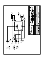
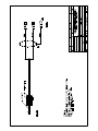
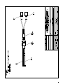
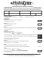
HydroLynx Systems, Inc.
Model 5351R
Receiver
Instruction Manual
Document No: A102680
Document Revision Date: August, 2006
HydroLynx Systems, Inc.
Model 5351R Receiver
Receiving and Unpacking
Carefully unpack all components and compare to the packing list. Notify HydroLynx
Systems immediately concerning any discrepancy. Inspect equipment to detect any
damage that may have occurred during shipment. In the event of damage, any claim for
loss must be filed immediately with the carrier by the consignee. If the equipment was
shipped via Parcel Post or UPS, contact HydroLynx Systems for instructions.
Returns
If equipment is to be returned to the factory for any reason, call HydroLynx between
8:00 a.m. and 4:00 p.m. Pacific Time to request a Return Authorization Number (RA#).
Include with the returned equipment a description of the problem and the name, address,
and daytime phone number of the sender. Carefully pack the equipment to prevent
damage during the return shipment. Call HydroLynx for packing instructions in the case of
delicate or sensitive items. If packing facilities are not available, take the equipment to the
nearest Post Office, UPS, or other freight service and obtain assistance with packaging.
Please write the RA# on the outside of the box.
Warranty
HydroLynx Systems warrants that its products are free from defects in material and
workmanship under normal use and service for a period of one year from the date of
shipment from the factory. HydroLynx Systems' obligations under this warranty are limited
to, at HydroLynx's option: (I) replacing; or (ii) repairing; any product determined to be
defective. In no case shall HydroLynx Systems' liability exceed product's original purchase
price. This warranty does not apply to any equipment that has been repaired or altered,
except by HydroLynx Systems, or that has been subjected to misuse, negligence, or
accident. It is expressly agreed that this warranty will be in lieu of all warranties of fitness
and in lieu of the warranty of merchantability.
Address
HydroLynx Systems, Inc.
950 Riverside Pkwy., Suite 10
West Sacramento, CA 95605
Phone: (916) 374-1800
Fax: (916) 374-1877
E-mail: [email protected]
Copyright 8 2006 by HydroLynx Systems, Inc.
Page 2
A102680
Model 5351R Receiver
HydroLynx Systems, Inc.
TABLE OF CONTENTS
SECTION NO.
PAGE NO.
1.0 INTRODUCTION....................................................................................................... 5
1.1 General Description ....................................................................................... 5
1.2 Equipment Included........................................................................................ 5
1.3 Specifications ................................................................................................. 5
2.0 INSTALLATION......................................................................................................... 5
2.1 Site Selection ................................................................................................. 5
2.1.1 Antenna ............................................................................................ 5
2.1.2 5351R .............................................................................................. 6
2.2 Connections ................................................................................................... 6
2.3 Mounting......................................................................................................... 6
3.0 THEORY OF OPERATION ....................................................................................... 6
3.1 Power Light .................................................................................................... 6
3.2 Radio: Tone and Squelch............................................................................... 7
3.3 Input/Output ................................................................................................... 7
4.0 TESTING AND MAINTENANCE ............................................................................... 7
4.1 Testing............................................................................................................ 7
4.1.1 RF Antenna Test............................................................................... 7
4.1.2 Tone Out .......................................................................................... 7
4.2 Radio Alignment ............................................................................................. 7
4.3 Maintenance................................................................................................... 8
5.0 FORMS AND DRAWINGS ........................................................................................ 8
A102680
Page 3
HydroLynx Systems, Inc.
Page 4
Model 5351R Receiver
A102680
Model 5351R Receiver
HydroLynx Systems, Inc.
1.0 INTRODUCTION
1.1 General Description
The 5351R is an FM radio receiver that operates with a frequency in the VHF or UHF
band. The frequency used for each system is selected by the customer. Within the United
States, the frequency must be applied for and approved for use by the FCC.
1.2 Equipment Included
5351R
Receiver/Decoder Cable
5030 Charger with 5-pin female connector
Battery Power Cable
Battery
1.3 Specifications
Enclosure:
Radio specifications:
Power Required:
Standby Current:
Battery:
Charger:
Antenna Connector:
Audio Output Level:
Operating temperature:
Size:
Weight:
Desktop
Refer to radio manual
12 Vdc
65 mA
12 Vdc, 12 AH
120 Vac, 0.2 A
N-type female lightning arrestor
800 mVp-p, Typical
-40 to 60 °C
7.25 in. x 2.75 in. x 9 in.
3 lbs
2.0 INSTALLATION
The 5351R/D Receiver/Decoder is composed of two devices; a radio receiver; and a
demodulator. The 5351R radio receiver is installed at or near the antenna tower. The
5351D decoder is installed at or near the operator's office.
2.1 Site Selection
2.1.1 Antenna
The receiver antenna should be installed at an elevation that is as high as practical. If
possible, install the antenna onto a radio tower, tall building, or other tall structure. Refer to
Radio Path Survey.
A102680
Page 5
HydroLynx Systems, Inc.
Model 5351R Receiver
2.1.2 5351R
The 5351R must be installed as close to the antenna as possible to keep antenna cable
line loss to a minimum. The 5351R is capable of driving its output signal long distances, up
to 5000 feet (consult factory). For outdoor or remote installations, the 5351R must be
housed within a weather-proof enclosure; otherwise it must be kept indoors.
2.2 Connections
All wiring connections are located on the back panel.
! Connect the antenna cable into the N-type female connector.
! Attach the ground screw to earth ground using a #6 stranded copper wire. The ground
lug is provided on the ground screw.
! Attach the receiver/decoder cable using the "lug" type connectors into the Sig Out
(signal out) section of the terminal block. Attach the cable shield to the ground screw
(see wiring diagram).
! Attach the battery power cable into the terminal block. Connect battery power cable to
the battery terminals.
CAUTION: Failure to observe battery polarity will cause extensive damage.
! Connect the AC charger to the 5-pin connector. Plug the AC charger into a standard
AC electrical outlet.
2.3 Mounting
The 5351R is designed for "desktop" installation. Avoid placing the console in areas where
there is a possibility of it getting wet. For use in remote locations, place the console into a
weather-proof enclosure.
3.0 THEORY OF OPERATION
The 5351R receives data transmissions from the remote sites. The receiver circuitry
demodulates the Frequency Modulated (FM) radio signals into audible tones for input into
the 5351D.
3.1 Power Light
The power light is lighted whenever power is applied to the 5351R.
Page 6
A102680
Model 5351R Receiver
HydroLynx Systems, Inc.
3.2 Radio: Tone and Squelch
The tone amplitude and squelch levels are factory set.
CAUTION: Adjustment should be made only by trained service personnel.
Tone amplitude is 800 mV
Squelch is set to 12db (SINAD measurement); Limit: <=0.5 •V.
3.3 Input/Output
The 5351R receives Radio Frequency (RF) data transmissions from remote sites as input.
The receiver circuitry demodulates the Frequency Modulation (FM) signals into audible
tones. These tones, presented in ALERT Format, are 2133 Hz for logic "1" and 1920 Hz for
a logic "0", and are the Frequency Shift Keying (FSK) output signal.
4.0 TESTING AND MAINTENANCE
4.1 Testing
4.1.1 RF Antenna Test
The antenna is tested for reflected power as if it were a transmitter antenna.
! Attach a wattmeter and transmitter to the antenna cable.
! Select the proper slug for reverse power and frequency testing (refer to wattmeter
manual).
! Initiate a transmission. The duration of the transmission must be long enough to obtain
a stable reading on the wattmeter.
! Compare the measured reading to the antenna system's rated reflected power.
4.1.2 Tone Out
!
!
!
!
Attach an oscilloscope to the tone out terminals.
Initiate a transmission to the receiver.
Verify that the signal is a 800 mVpp sine wave.
Refer to the radio manufacturer's service manual for adjustment instructions.
4.2 Radio Alignment
Refer to the Incoming Radio Inspection Form and to the radio manufacturer's service
manual.
CAUTION: Radio alignment should only be performed by trained service personnel.
A102680
Page 7
HydroLynx Systems, Inc.
Model 5351R Receiver
4.3 Maintenance
The receiver is essentially a low maintenance item, however, the battery should be tested
annually and replaced whenever necessary. Refer to the battery manual.
5.0 FORMS AND DRAWINGS
AC103421
AC106249
AC108053
A100913
Page 8
Wiring Diagram - Chassis
Assembly - Audio Cable to Decoder
Assembly - Battery Cable
Incoming Radio Acceptance Procedure
A102680
Incoming Radio Acceptance Procedure
1. GENERAL PROCEDURE
Document No. A100913-1
This is a generic procedure for accepting a new or repaired radio. Separate sections divide the procedure into receiver and transmitter
functions. If the radio requires tuning, refer to the manufacturer's radio service manual. When HydroLynx specifications are
unavailable, use the manufacturer's radio specifications. Record the test results on this sheet. Record general information here:
Inspector
Chassis serial number
Date
Radio serial number
Model Radio manufacturer
Frequency
Mhz
Radio model number
Deviation
Power
±kHz
2. REQUIRED EQUIPMENT
G radio service monitor
G SINAD meter
G oscilloscope
W
G miscellaneous tuning wands
3. TRANSMITTER
Frequency Error
G Key the transmitter with no tone in. Observe frequency error:
G Limit frequency error # ±500 Hz:
Hz
Yes G No G
Power Out
G Key the transmitter. Observe power out:
G Limit within specifications:
Deviation
G Inject tone as specified by the HydroLynx model or radio specification. Observe deviation (adjust as required):
G Limit within specifications:
4. RECEIVER
Frequency error and selectivity
G Inject carrier frequency: generator level = 10 :V and 1 :V
tone
= 1 kHz ±0.005 kHz
deviation
= ±3 kHz
G Increase carrier frequency, 1 kHz steps; observe SINAD meter. Record number of steps SINAD is above 12 dB:
G Decrease carrier frequency, 1 kHz steps; observe SINAD meter. Record number of steps SINAD is above 12 dB:
G Subtract these two values and enter the difference:
G Limit the recorded difference # 5 kHz:
Sensitivity
G Inject carrier frequency; reduce the generator level until 12 dB SINAD is observed:
G Limit generator level # 0.5 :V at 12 dB SINAD
W
Yes G No G
±
kHz
Yes G No G
kHz
kHz
kHz
Yes G No G
:V
Yes G No G
Squelch
G Adjust the squelch threshold at generator level which produces 12 dB SINAD.
G Limit unsquelch and squelch when generator level is slightly increased and decreased:
Yes G No G
Tone Out
G Inject carrier frequency: generator level = 10 :V
tone
= 2 kHz ±0.2 kHz
deviation
= ±3 kHz or work order specification
G Observe the tone output with the oscilloscope and adjust to 0.8 Vpp (or specified).
G Limit within specifications:
Yes G No G
HydroLynx Systems, Inc. ! 950 Riverside Pkwy., Suite 10 ! West Sacramento, CA 95605
Phone 916-374-1800 ! Fax 916-374-1877 ! Email [email protected]
Vpp