1
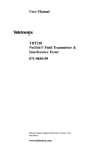
HydroLynx Systems, Inc.
Model 50386RP
Model 50386RP-2
Real Time Data Repeater
Instruction Manual
Document No: WD102685
Document Revision Date: April 2011
HydroLynx Systems, Inc.
Model 50386RP Real Time Data Repeater
Receiving and Unpacking
Carefully unpack all components and compare to the packing list. Notify HydroLynx
Systems immediately concerning any discrepancy. Inspect equipment to detect any
damage that may have occurred during shipment. In the event of damage, any claim for
loss must be filed immediately with the carrier by the consignee. If the equipment was
shipped via Parcel Post or UPS, contact HydroLynx Systems for instructions.
Returns
If equipment is to be returned to the factory for any reason, call HydroLynx between
8:00 a.m. and 4:00 p.m. Pacific Time to request a Return Authorization Number (RA#).
Include with the returned equipment a description of the problem and the name, address,
and daytime phone number of the sender. Carefully pack the equipment to prevent
damage during the return shipment. Call HydroLynx for packing instructions in the case of
delicate or sensitive items. If packing facilities are not available, take the equipment to the
nearest Post Office, UPS, or other freight service and obtain assistance with packaging.
Please write the RA# on the outside of the box.
Warranty
HydroLynx Systems warrants that its products are free from defects in material and
workmanship under normal use and service for a period of one year from the date of
shipment from the factory. HydroLynx Systems' obligations under this warranty are limited
to, at HydroLynx's option: (i) replacing; or (ii) repairing; any product determined to be
defective. In no case shall HydroLynx Systems' liability exceed product's original purchase
price. This warranty does not apply to any equipment that has been repaired or altered,
except by HydroLynx Systems, or that has been subjected to misuse, negligence, or
accident. It is expressly agreed that this warranty will be in lieu of all warranties of fitness
and in lieu of the warranty of merchantability.
Address
HydroLynx Systems, Inc.
950 Riverside Pkwy., Suite 10
West Sacramento, CA 95605
Phone: (916) 374-1800
Fax: (916) 374-1877
E-mail: [email protected]
Copyright 8 2011 by HydroLynx Systems, Inc.
Page 2
WD102685
Model 50386RP Real Time Data Repeater
HydroLynx Systems, Inc.
TABLE OF CONTENTS
SECTION NO.
PAGE NO.
1.0 INTRODUCTION ................................................................................................................... 6
1.1 General Description .................................................................................................. 6
1.2 Equipment Included .................................................................................................. 6
1.3 Specifications (Refer to manufacturer’s manuals for radio specifications.)..... 6
2.0 INSTALLATION ..................................................................................................................... 7
2.1 Site Selection ............................................................................................................. 7
2.1.1 Radio Path................................................................................................... 7
2.1.2 Accessibility................................................................................................. 7
2.2 Assembly .................................................................................................................... 7
3.0 THEORY OF OPERATION.................................................................................................. 8
3.1 Inputs/Outputs............................................................................................................ 8
3.1.1 FM Receiver................................................................................................ 9
3.1.2 Modem PCB................................................................................................ 9
3.1.3 SLB and PCOS........................................................................................... 9
3.1.4 Transmitter .................................................................................................. 9
3.2 Controls....................................................................................................................... 9
3.2.1 Configuration files ...................................................................................... 9
3.2.1.1 S&F_RPTR.cfg...................................................................................... 10
3.2.1.2 S&F_RPT2.cfg ...................................................................................... 10
3.2.2 ScadaLynx Toolbox Communications Tab .......................................... 10
3.2.2.1 Transmit Sub-Tab................................................................................. 11
3.2.2.1.1 Transmit Timers................................................................................. 11
3.2.2.1.2 Transmit Parameters ........................................................................ 12
3.2.2.1.3 Carrier Detect..................................................................................... 12
3.2.2.1.4 Transmit Alarms ................................................................................ 13
3.2.2.1.5 Test Transmit ..................................................................................... 13
3.2.2.2 Receiver Sub-Tab................................................................................. 13
3.2.2.2.1 Receiver Timers................................................................................. 14
3.2.2.2.2 Receiver Parameters ........................................................................ 14
3.2.2.2.3 Receiver Control................................................................................ 14
3.2.2.3 Repeater Sub-Tab ................................................................................ 15
3.2.2.3.1 Repeater Timers................................................................................ 15
3.2.2.3.2 Repeater Repeat on Ports ............................................................... 16
3.2.2.3.3 Repeat on Port Repeat Range........................................................ 16
3.2.2.3.3.1 Add a Repeat Range..................................................................... 18
3.2.2.3.3.2 Edit a Repeat Range ..................................................................... 18
3.2.2.3.3.3 Delete a Repeat Range ................................................................ 18
3.2.3 ScadaLynx Toolbox I/O Tab................................................................... 18
3.2.3.1 Battery Check ID................................................................................... 19
3.2.3.2 Battery Voltage Scaling ....................................................................... 19
3.2.3.3 Battery Voltage Reporting Sub-Tab................................................... 19
3.2.4 ScadaLynx Toolbox Reports Tab .......................................................... 19
3.2.5 Switches: ID, Reset, and Test................................................................ 20
WD102685
Page 3
HydroLynx Systems, Inc.
Model 50386RP Real Time Data Repeater
3.2.5.1 ID Switches - S1 thru S4 ..................................................................... 20
3.2.5.2 Reset Switch.......................................................................................... 21
3.2.5.3 Test Switch ............................................................................................ 21
3.2.6 LED’s: Run, ALERT RX, ALERT TX, Analog power, Test. ............... 21
3.2.6.1 RUN LED................................................................................................ 21
3.2.6.2 ALERT RX LED..................................................................................... 21
3.2.6.3 ALERT TX LED ..................................................................................... 21
3.2.6.4 Analog Power LED ............................................................................... 21
3.2.6.5 Test LED ................................................................................................ 21
3.2.7 Console Monitor ....................................................................................... 22
3.2.7.1 ScadaLynx Toolbox Monitor ............................................................... 22
3.2.7.2 HyperTerminal Console Monitor ........................................................ 23
3.2.8 Radio Alignment ....................................................................................... 24
4.0 MAINTENANCE, TESTING AND TROUBLESHOOTING ............................................ 24
4.1 Maintenance............................................................................................................. 24
4.1.1 Routine Maintenance .............................................................................. 24
4.1.2 Maintenance Report ................................................................................ 24
4.2 Testing....................................................................................................................... 25
4.2.1 Repeater Function Testing ..................................................................... 25
4.2.2 Transmit Testing....................................................................................... 25
4.2.2.1 Deviation ................................................................................................ 26
4.2.2.2 Frequency Error .................................................................................... 26
4.2.2.3 Output Power......................................................................................... 26
4.2.2.4 Reflected Power Test........................................................................... 27
4.2.2.5 TX Audio P5 pin 1................................................................................. 27
4.2.2.6 PTT P5 pin 2.......................................................................................... 27
4.2.3 Receiver Testing ...................................................................................... 27
4.2.3.1 RX Audio: P5 pin 5 ............................................................................... 27
4.2.3.2 Carrier Detect (CD): P5 pin 7.............................................................. 28
4.2.3.3 RF Receive Antenna ............................................................................ 28
4.2.4 Repeater Tests ......................................................................................... 28
4.2.4.1 Repeater Wait Timer............................................................................ 28
4.2.4.2 Talkback Wait Timer ............................................................................ 28
4.2.4.3 Receive On During Transmit............................................................... 29
4.2.4.4 Repeat ID Range Table ....................................................................... 29
4.3 Radio Alignment ...................................................................................................... 29
4.4 Troubleshooting ....................................................................................................... 30
4.4.1 Power P5 & P1 ......................................................................................... 30
4.4.2 Signal Out & Signal In ............................................................................. 30
5.0 FORMS AND DRAWINGS ................................................................................................ 30
5.1 Forms ........................................................................................................................ 30
5.2 Drawings ................................................................................................................... 30
Page 4
WD102685
Model 50386RP Real Time Data Repeater
WD102685
HydroLynx Systems, Inc.
Page 5
HydroLynx Systems, Inc.
Model 50386RP Real Time Data Repeater
1.0 INTRODUCTION
1.1 General Description
The Models 50386RP and 50386RP-2 Data Repeater relays ALERT Protocol data
between remote sites and a central site where direct line-of-sight radio paths do not exist.
As a standard ALERT repeater, the 50386RP is equipped with an FM transceiver to both
receive and transmit data on a single antenna. The 50386RP-2 uses a separate FM
receiver and FM transmitter, this configuration is used when two antennas are employed,
an omni for the receiver and a directional for the transmitter.
Programmable features of the 50386RP make it a versatile ALERT repeater. The Repeat
on Port Repeat Range, which lists the ALERT ID numbers to be repeated on a given
communications port, allow the repeaters to be updated in the field. It also employs a
programmable Talkback Wait timer. This feature eliminates duplicate reports and datalooping in ALERT radio networks with multiple repeaters.
Many repeater configurations are available because of the many expanded features of the
50386 that includes multi-communication pathways and sensor inputs. With the addition of
optional equipment, the 50386 will receive and repeat data on various data collection
networks and will include on-site data collection.
1.2 Equipment Included
Model 50386RP(-2) Data Repeater includes:
1> FM Transceiver (or FM Receiver and FM Transmitter)
2> SLB and PCOS boards
3> Modem Board
4> Can Assembly
5> Rechargeable Battery - 18 AHr
6> RF Power Amp (optional)
1.3 Specifications (Refer to manufacturer’s manuals for radio specifications.)
Size:
Weight:
Antenna connector(s):
Antenna input impedance:
Standby current (RX):
Operating current:
Squelch sensitivity:
Transmission current:
Power out (RF):
Power Amp current:
Power Amp Power out:
Page 6
8" diameter x 23" tall
11 lbs. (w/o battery)
BNC female
50 ohms
65 milliamps
150 milliamps
-113dBm
2 Amps
5 Watts
7.0 Amps (optional)
20 Watts (optional)
WD102685
Model 50386RP Real Time Data Repeater
HydroLynx Systems, Inc.
2.0 INSTALLATION
The 50386RP Repeater is self-contained and can be installed into protected environments
such as standpipes, NEMA-4X enclosures, blockhouses, and buildings. Refer to the Basic
Gauge and 50386P Packaged Repeater manuals for information on standpipe installation.
2.1 Site Selection
The radio path is the most important criteria for locating any repeater site. In many cases,
suitable locations for correcting radio path problems will be limited and there may be
existing radio equipment structures at these sites, presenting logistical and radio
equipment challenges. In these cases, co-ordination with the owners of the equipment
structures will be paramount to a successful installation.
2.1.1 Radio Path
To ensure proper equipment operation, a radio path survey and verification must be
completed before installing the 50386RP Repeater. Refer to the Radio Path Manual,
Document number WP102715.
2.1.2 Accessibility
Access to the site is the other criteria to consider in site selection. When the repeater is
placed in an equipment structure owned by another entity, it is best to negotiate unlimited
access to the site for your agency. Otherwise, your ALERT system functionality becomes
dependant on that other entity and their priorities.
The other concern with access is the ability to get to the site year round. If weather limits
your access to the site then your network functional reliability becomes dependant on the
weather.
2.2 Assembly
The 50386RP and the 50386RP-2 assembly involve connecting the chassis input/output
and power. For standpipe assembly refer to the 50386P Packaged Repeater manual,
Document number WD102677.
$ Connect the antenna cable connector to the ANTENNA port. For dual antenna, connect
the omni antenna to the RX ANTENNA port and the directional antenna to the TX
ANTENNA port.
$ Connect power harness to the battery.
CAUTION:
WD102685
Observe correct polarity. Failure to correctly connect the battery will cause
extensive damage.
Page 7
HydroLynx Systems, Inc.
Model 50386RP Real Time Data Repeater
$ Lower the battery into the can.
$ Connect solar panel or AC charger 3-pin female connector into the 12Vdc port.
CAUTION:
Connect the solar panel or AC charger only after the battery has been
connected.
$ Plug AC charger into AC outlet (if used).
$ Test the 50386RP functionality. Refer to section 4.2.1 Repeater Function Testing.
$ Place the 50386RP chassis into the can.
$ Tighten the latch knobs.
3.0 THEORY OF OPERATION
The 50386RP is an ALERT "store and forward" repeater. The FM transceiver demodulates
data received from the remote site. ALERT audio data is then processed through the
modem PCB, ScadaLynx Board (SLB), and the PC on a Stick (PCOS). A decision to repeat
the data is made based on the parameters in the configuration file: S&F_RPTR.cfg. For
repeated data, an ALERT data message is created and sent to the FM transceiver.
The 50386RP-2 can act as a “straight through” type repeater, meaning that it is possible to
receive data reports with the FM receiver while it is transmitting repeated data reports on
the FM transmitter. Care must be taken with this configuration to ensure separation
between the RX and TX frequencies and their antennas. The default configuration file for
this is S&F_RPT2.cfg.
Besides the configuration file, which controls the repeater automatically, the user can
control certain functions manually; through the ScadaLynx Toolbox, a HyperTerminal
connection, or switches on the SLB. Indicators which show the functionality of the
50386RP are the ScadaLynx Toolbox monitor, the HyperTerminal monitor, and the LED’s
on the SLB.
3.1 Inputs/Outputs
As an ALERT Repeater, the 50386RP’s main Input/Output is an ALERT Protocol data
transmission. The only other Input is the Battery Voltage as a sensor data point.
The 50386RP is capable of many additional functions beyond the standard ALERT
repeater. It can act as a data collection platform in the standard ALERT packaged stations,
act as a node between different data collection systems, and perform SCADA controls.
Refer to the 50386 DCU Operating Manual, Document number WD102711; the ScadaLynx
50386 Toolbox User’s Manual, Document number WD102712; and the appropriate
Packaged Station manual for further information on these functions.
Page 8
WD102685
Model 50386RP Real Time Data Repeater
HydroLynx Systems, Inc.
3.1.1 FM Receiver
Input to the receiver is a Radio Frequency (RF) Frequency Modulated (FM) ALERT
Protocol data transmissions. The receiver demodulates the FM signals into Frequency Shift
Keyed (FSK) audio tones. These ALERT Protocol FSK tones are the receiver signal output
to the modem PCB. Refer to Section 4.2.3.1 RX Audio: P5 pin 5.
3.1.2 Modem PCB
The modem PCB inputs the FSK tones and performs two tasks. First, the modem filters the
audio tones for output to the SLB. Second, the modem determines if a valid ALERT
message is being received. This task controls the Carrier Detect (CD) signal output to the
SLB. Refer to Section 4.2.3.2 Carrier Detect (CD): P5 pin 7.
3.1.3 SLB and PCOS
The 50386RP SLB and PCOS receive the filtered ALERT FSK audio tones and CD signal
as inputs (see Section 3.2.6.2 ALERT RX LED). When a CD signal is received, the ALERT
FSK tones are decoded into an ALERT ID number and Data value and stored into memory.
The ID number and Data value are compared and if the repeat criteria are met an ALERT
data FSK tone message is created and sent to the transmitter along with a Push-To-Talk
(PTT) signal (see Section 3.2.6.3 ALERT TX LED).
3.1.4 Transmitter
The transmitter inputs the FSK tones and PTT signal. The PTT signal enables the
transmitters RF Carrier output. The tones are modulated onto the RF carrier and sent as
an RF FM ALERT Protocol data transmission to the central site completing the repeater
function. Refer to Section 4.2.2 Transmit Testing.
3.2 Controls
The Configuration file controls the automatic ALERT Repeater functions. Manual testing of
the repeater is accomplished through the Test Tab in the ScadaLynx Toolbox, through the
HyperTerminal Console function keys, or hardware switches on the SLB PCB.
Some of the information in this section is taken from the ScadaLynx 50386 Toolbox User’s
Manual, Document number WD102712, and the 50386DCU Operating Manual, Document
number WD102711. The information included in this section deals directly to the function
of the repeater. To understand the complete functions of the software parameters and
hardware mentioned in this section, refer to those manuals.
3.2.1 Configuration files
There are two standard configuration files for the 50386RP: S&F_RPTR.cfg and
S&F_RPT2.cfg. These files correspond to the two standard ALERT Repeater Packaged
Stations: 50386P and 50386P-2.
WD102685
Page 9
HydroLynx Systems, Inc.
Model 50386RP Real Time Data Repeater
S&F refers to “Store and Forward”; this follows the ALERT convention which separates
repeaters into two categories, which are the “Store and Forward” and the “Straight
Through” (ST).
The ST repeater was the first generation repeater. It utilized a separate receiver and
transmitter. The output of the receiver was connected to the input of the transmitter. The
disadvantage was that the receive and transmit frequency required, nominally, 4 MHz
separation. The advantage was the duty cycle was 100%; i.e. the receive was active while
transmitting.
The S&F repeater allows the use of a single frequency for receive and transmit. The
disadvantage is that the duty cycle is reduced to 50%; i.e. the receive is disabled while
transmitting. But there are other advantages to the S&F repeater besides using a single
frequency. The repeater becomes “smart” and can make decisions whether or not to
forward the stored data packet. There were two basic configurations of the S&F repeater;
PASS ALL, which passed all valid ALERT ID data packets and PASS BLOCK, which
passed ALERT ID’s that were included in a programmed block of ID numbers.
The 50386RP can provide the utility of both; the ST configuration still requires using two
radios on separate frequencies with a nominal separation of 1 MHz.
3.2.1.1 S&F_RPTR.cfg
The S&F_RPTR.cfg configuration file’s default parameters are programmed for a PASS
ALL ALERT radio repeater with one radio, one antenna, and no inputs other than the
battery voltage. These parameters will be discussed in the following sections. This
configuration can be easily modified to include a list of ID numbers to pass to create a
PASS BLOCK configuration, i.e. Repeat on Port Repeat Range, refer to section 3.2.2.3.3.
3.2.1.2 S&F_RPT2.cfg
The S&F_RPT2.cfg differs from the one above in that the configuration file’s default
parameters are programmed for a PASS ALL ALERT radio repeater with two radios and
two antennas. The separation of the receive and transmit frequencies determines whether
the repeater is programmed to receive while transmitting.
3.2.2 ScadaLynx Toolbox Communications Tab
The 50386 has a dedicated hardware ALERT Radio Port. The functionality of this port is
controlled by configuration parameters located under the ScadaLynx Toolbox
Communications Tab.
The upper section of the Communications Tab is divided into two sub sections: the Port
List displays available ports and their parameters; the Identification section is where the
parameters are selected.
For repeater operation, the Type parameter is set to Radio and the Function parameter is
set to Repeater. These parameter settings enable the Communications Sub-Tabs,
Transmit, Receiver, and Repeater, located in the lower section.
Page 10
WD102685
Model 50386RP Real Time Data Repeater
HydroLynx Systems, Inc.
3.2.2.1 Transmit Sub-Tab
.
The Transmit Sub-Tab is divided into five (5) sections: Transmit Timers, Transmit
Parameters, Carrier Detect, Transmit Alarms, and Test Transmit.
3.2.2.1.1 Transmit Timers
The Transmit Timers section controls the radio switched power and the PTT signal
with these timers:
• Power On
• Power Off
• PTT On
• PTT Off
WD102685
Page 11
HydroLynx Systems, Inc.
Model 50386RP Real Time Data Repeater
The Power On timer is used to warm-up a transmitter during the power-up process. The
Power Off timer insures that all the transmitter functions have completed before the radio
is powered-down. The timer parameters are dependant on whether the repeater uses a
transceiver, S&F_RPTR, or separate receiver and transmitter, S&F_RPT2.
When a transceiver is used, S&F_RPTR, the radio power is on constantly; so, there is no
need to wait for the radio to warm-up nor wait after PTT is dropped for the transmission to
be sent. The parameters are both (0) zero:
Power On:
Power Off:
0
0
When a separate transmitter is used, S&F_RPT2 the
standard parameter values are used:
Power On:
Power Off:
400
50
The PTT On and PTT Off timers are not dependant on the
repeater configuration and both use standard parameter
values:
PTT ON:
PTT OFF:
100
50
3.2.2.1.2 Transmit Parameters
The Transmit Parameters section controls the preamble
length, data format, hold-off, and transmit offset times.
The Transmit Parameters are:
•
•
•
•
•
Preamble Length
Format
Hold-off Wait
Timed Offset
Event Offset
The repeaters use standard parameter values.
3.2.2.1.3 Carrier Detect
The Carrier Detect section controls a “Listen before Talk” feature for transmitters
utilizing radio transceivers.
The Carrier Detect parameters are:
•
•
•
Carrier Detect Check
Carrier On Wait
Carrier Drop Wait
Page 12
WD102685
Model 50386RP Real Time Data Repeater
HydroLynx Systems, Inc.
Since receiving data reports is part of the repeater function, these Carrier Detect
parameters are redundant to the receive carrier detect parameters. The default parameters
are used in most cases with one exception. These parameters are disabled by de-selecting
the Carrier Detect Check box when the 50386RP-2, using S&F_RPT2.cfg, is used as a ST
repeater. Refer to section 3.2.2.2.2 Receiver Parameters.
3.2.2.1.4 Transmit Alarms
The Transmit Alarms section controls the repeat count and format for alarm
transmissions; they are not applicable to standard repeater function.
Transmit Alarms parameters are:
•
•
Alarm repeat count
Alarm Format
3.2.2.1.5 Test Transmit
The Test Transmit section controls the radio for testing purposes.
The Test Transmit buttons can be used to test the radio transmitter:
•
Test Transmit Data
•
•
•
•
Test Transmit Dual Tones
Test Transmit High Tone
Test Transmit Low Tone
Test Transmit No Tone
Read and transmit point data for
points reporting on port.
Transmit alternating tone on port.
Transmit high tone on port.
Transmit low tone on port.
Transmit no tone, carrier only.
3.2.2.2 Receiver Sub-Tab
The Receiver Sub-Tab is divided into three sections: Receiver Timers, Receiver
Parameters, and Receiver Controls. The Receiver Parameters have values set based
on the repeater configuration or for testing purposes.
WD102685
Page 13
HydroLynx Systems, Inc.
Model 50386RP Real Time Data Repeater
3.2.2.2.1 Receiver Timers
Receiver Timers are:
•
Receive Wait
The repeaters use standard parameter value which is 100.
3.2.2.2.2 Receiver Parameters
Receiver Parameters are:
•
•
•
Format
Receiver On During Transmit
Log Data Received
The Receiver On During Transmit parameter is selected or
de-selected based of the repeater radio configuration.
S&F_RPTR, with a transceiver, must de-select this parameter.
S&F_RPT2; with separate receive and transmit radios, and a
minimum of 1MHz frequency separation between the receive
and transmit frequencies; may have this parameter selected.
When selected the Log Data Received parameter writes
received data reports to the log data file on the DCU flash storage. These logged data
reports can be downloaded by the Toolbox. These reports can provide useful information
when used in short term tests. This parameter should never be selected as part of an
operational configuration file.
Warning! Logging data to DCU flash storage will affect DCU repeater performance.
When the DCU writes received data reports to flash storage it may miss additional
data reports that follow.
3.2.2.2.3 Receiver Control
Receiver Control types are:
•
•
•
•
Complementary Pair
MODBUS
ScadaLynx
Standard ALERT
The Receiver Control is disabled as part of the standard
ALERT repeater by setting the Type parameter to
ScadaLynx.
Page 14
WD102685
Model 50386RP Real Time Data Repeater
HydroLynx Systems, Inc.
3.2.2.3 Repeater Sub-Tab
The Repeater Sub-Tab is divided into three sections: Repeater Timers, Repeat on
Ports, and Repeat on Port Repeat Range.
The parameters in these three sections affect the actual repeater functionality, as may be
deduced from the sub-tab title. The Repeat on Ports are based on the ALERT repeater
configuration and are the same for both S&F_RPTR and S&F_RPT2 configuration files.
The parameters in the Repeater Timers and the Repeat on Port Repeat Range sections
are dependant on the specifications of the ALERT System where the repeater is deployed.
Therefore, the user may customize these parameters to optimize the repeater performance
based on the repeater’s location.
3.2.2.3.1 Repeater Timers
The parameters in the Repeater Timers section are intended for use in ALERT Systems
with multiple repeaters. Repeater Timers parameters are:
•
•
•
Repeat Wait
Talkback Wait
Talkback Test
The Repeat Wait parameter delays the repeat transmission.
The intended use is in redundant repeater systems. The delay
allows the main repeater to complete its transmission before
the redundant repeater starts its transmission.
The default parameter value is 0 milliseconds (msecs), which is no delay.
A parameter value of 1200 milliseconds will allow an S&F_RPTR transmission with four
data packets. This includes 400 msecs warm-up time, 100 msecs preamble, 4 x 133
msecs data reports and 168 msecs processing time (fudge factor) for a total of 1200
msecs. If the expected length of the ALERT transmission is more or less than four, the
parameter value may be adjusted by 133 msecs for each data packet.
The Talkback Wait parameter is the length of time, in seconds, that a duplicate received
data packet will not repeated. Duplicate report packets have matching ID and data.
The default parameter value is 5 seconds.
WD102685
Page 15
HydroLynx Systems, Inc.
Model 50386RP Real Time Data Repeater
One unintended consequence of multiple repeaters is “Talkback.” Talkback is described as
the situation when the repeater output transmission eventually returns as an input
transmission. In theory, the looped transmissions could go on infinitely, in practice the
transmission is soon corrupted and the loop broken; but not before multiple reports are
received at the base station(s).
In most situations, 5 seconds is more than sufficient to eliminate talkback; however, in rare
instances when multiple ALERT Systems, having multiple repeaters, create a repeater loop
the cycle can extend beyond 5 seconds. This parameter value is mostly arbitrary. The only
concern is that a valid data report of identical value might get blocked. A parameter value
of 10 seconds should eliminate even the most complex loops without disrupting valid data
reports. But the user needs to make this determination.
The Talkback Test parameter allows the user to define a duplicate packet as matching the
ID and Data or as matching the ID Only. Due to the ALERT Protocol, it is possible that a
ALERT data packet’s data value gets corrupted but it can still pass the test as a valid
ALERT message. By using only the ID as the match criterion the possibility of the looping
data packet looking like a new valid ALERT report is eliminated.
The Talkback Test type is ID and Data by default. Select ID Only if your ALERT System
talkback problem corrupts report data values.
3.2.2.3.2 Repeater Repeat on Ports
The Repeat on Ports is the essential parameter which
defines the 50386 as an ALERT Repeater
The default parameter value is selected such that the
ALERT port has the Repeat on Port box selected.
Selecting this box displays “Yes” for the selected port
under the Repeat column.
3.2.2.3.3 Repeat on Port Repeat Range
Each communication port has a unique list of repeat ranges. Select a port in the Report on
Port list to display and edit the Repeat on Port Repeat Range.
This repeater section is a very useful programmable list of ID’s that the ALERT Repeater
will PASS; PASS is a term used by the original ALERT S&F repeaters. To explain the
usefulness of the Repeat on Port Repeat Range list it will be helpful to understand how
those original ALERT S&F repeaters where configured; because it is the functions of the
PASS ALL and PASS BLOCK configurations which are represented in this section.
PASS ALL is the default configuration and is represented by a list with either no entries or
one entry that includes the entire range of ALERT ID’s (0 – 8191).
Page 16
WD102685
Model 50386RP Real Time Data Repeater
HydroLynx Systems, Inc.
PASS BLOCK configuration enabled the user to specify a block of ID’s that a singular
repeater in a system will PASS. This block of ID’s existed as a part of the firmware program
in the original ALERT S&F repeaters. To change the block required that the EPROM be
reprogrammed. Also, the blocks were divided into fixed lengths of 255 ID’s, and while it
was possible to program individual ID’s; all this programming required changing the
Machine Code which should be considered the extreme opposite of “User Friendly.”
In a multiple repeater ALERT System, it is possible that more than one repeater will be
able to receive and repeat a data transmission from a given remote site, To eliminate
redundant reports, the repeaters were programmed so that only one of the repeater’s
PASS BLOCK list contains the remote site ID. This was also one way to eliminate talkback
between the two repeaters. This only worked to eliminate talkback when the repeaters
were on a separate radio path to the base station. Repeaters in a series, or “backbone”,
configuration must necessarily repeat the same ID’s.
The following sections are copied directly from the ScadaLynx 50386 Toolbox User’s
Manual, Document # WD102712, to assist the user and because of the utility which these
sections provide to customize the repeater function as a PASS BLOCK repeater.
Repeat range parameters are:
•
•
•
•
Type
Start ID
End ID
Offset ID
Multiple repeat ranges can be defined. We
recommend arranging the repeat range list
from smallest to largest Start ID. This helps
to avoid confusion about which ID numbers
are included in the list when there are a large number of repeat ranges. Refer to section
3.2.2.3.3.2 Edit a Repeat Range.
The range Type determines whether the DCU checks the DCU address in the packet or
the ID number in the data packet. Check the ID box for ALERT protocol.
A repeat range includes all ID numbers between the Start ID and the End ID.
Offset ID is a signed number that is added to the received ID before it is repeated. Use 0
to repeat the ID number without change.
In the example above, ID numbers in the range 2000 to 2500 and 3200 to 3499 are
repeated with no change to their ID numbers.
Note: If no repeat range is defined, all received packets are repeated.
WD102685
Page 17
HydroLynx Systems, Inc.
Model 50386RP Real Time Data Repeater
3.2.2.3.3.1 Add a Repeat Range
It is easier to copy and existing repeat range than adding a new range. To copy a repeater
repeat range:
1. Select the repeat range to copy from the list.
2. Change the Type, Start ID, End ID, or Offset ID and click Add.
3. Reposition the repeat range with the Up & Down arrow buttons and click Save.
3.2.2.3.3.2 Edit a Repeat Range
1. Select a repeat range from the list.
2. Change the Type, Start ID, End ID, or Offset ID and click Replace.
3. Reposition the repeat range with Up & Down arrow buttons and click Save.
3.2.2.3.3.3 Delete a Repeat Range
1. Select a repeat range from the list.
2. Click Delete then click Save.
3.2.3 ScadaLynx Toolbox I/O Tab
The configuration parameters that define the repeater battery voltage reporting are located
under the ScadaLynx Toolbox I/O Tab.
Page 18
WD102685
Model 50386RP Real Time Data Repeater
HydroLynx Systems, Inc.
3.2.3.1 Battery Check ID
Define the ID number for the repeater battery voltage. In the example above, the ID is
defined at an offset of +0 from the station ID which is 8190, so the battery voltage ID is
8190. The battery voltage on the DCU is read from Analog Input 16.
3.2.3.2 Battery Voltage Scaling
The battery voltage is read from a resistor network using the 0 … 5 Vdc ADC Input Range.
The scaled readings range from 0 … 16.0375 Vdc. The scaling parameter EX is computed
by dividing the scaled range by the ADC raw range: 16.0375 / 65535 = 0.000244717.
The Decimal Digits Displayed is set to two (2) to transmit the battery voltage in
hundredths of volts. For example a scaled reading of 12.56 is transmitted as 1256.
3.2.3.3 Battery Voltage Reporting Sub-Tab
The Reporting Sub-Tab allows the user to select the values for the parameters: Change,
Limit, and Report. It also displays the Timed Interval and Test Intervals parameter as
defined on the Reports Tab (see below). The default parameters are:
•
•
•
Change: 0.50
Limit:
10000.00
Report: 1: Battery 6 hour report
3.2.4 ScadaLynx Toolbox Reports Tab
The Reports Tab defines reporting schemes that are assigned to points in the DCU
configuration. In the S&F_RPTR configuration file, there is only one reporting scheme
named Battery 6 hour report.
WD102685
Page 19
HydroLynx Systems, Inc.
Model 50386RP Real Time Data Repeater
In this reporting scheme, the battery voltage is logged transmitted every six (6) hours on
the Timed Interval regardless of any change. The battery voltage is logged and
transmitted on the one (1) hour Test Interval if the reading changes by the reporting
changed defined on the Reporting Sub-Tab under the I/O Tab (see above).
3.2.5 Switches: ID, Reset, and Test
The manual I/O features allow the user to control, monitor and test the 50386RP repeater
functions. These features include ID switches, LEDs, jumpers, test points and an ALERT
Audio Out Adjustment (see Drawing WP108116 for PCB locations and pin-outs).
3.2.5.1 ID Switches - S1 thru S4
The repeater configuration can be set up to read the station ID number from the ID
switches. If this feature is enabled, the repeater station ID selection is set in the ID
switches with the least significant digit (ones) in switch S4 and the highest significant digit
(thousands) in switch S1.
For example, to set a station ID of 8190, set: S1 to 8, S2 to 1, S3 to 9 & S4 to 0.
Page 20
WD102685
Model 50386RP Real Time Data Repeater
HydroLynx Systems, Inc.
3.2.5.2 Reset Switch
The RESET switch S7 performs the same software reboot as powering-up the 50386RP;
however, it is recommended to perform the power-up reboot when it is necessary to insure
that all hardware latches are reset.
3.2.5.3 Test Switch
The TEST switch S8 will initiate a test sequence that will read all I/O points and transmit
data. The TEST switch does not wake up the 50386RP from power down mode. However,
within 15 seconds, the watchdog timer wakeup will detect the TEST switch down and start
the test sequence. To force a test without waiting for the watchdog timer wakeup, press the
RESET switch, wait for the TEST LED 5 to turn on then off, and then press the TEST
switch.
3.2.6 LED’s: Run, ALERT RX, ALERT TX, Analog power, Test.
The 50386 SLB has five LEDs that can be used to monitor 50386RP activity.
3.2.6.1 RUN LED
The RUN LED 4 is on the when the 386EX processor is running. When the 50386RP is in
low power mode, this LED is off. On power up the RUN LED flashes, stays on for 10
seconds then turns off when the 50386RP powers downs to low power mode.
3.2.6.2 ALERT RX LED
The ALERT RX LED 3 is on when the ALERT radio has carrier detect on and is receiving
valid ALERT tones. The ALERT RX LED is also turned on by telephone or radio modems
when carrier detect is on.
3.2.6.3 ALERT TX LED
The ALERT TX LED 1 is on when the ALERT radio transmit power is turned on. After data
is transmitted, the radio transmit power is turned off.
3.2.6.4 Analog Power LED
The Analog Power LED 2 is on when the sensor power is turned on. The sensor power is
turned on to read analog sensors such as the battery voltage.
3.2.6.5 Test LED
The Test LED 5 is on when the 50386RP is running a Test sequence or writing to the Flash
memory.
To prevent Flash memory corruption, do not remove power when the Test LED 5 is on.
WD102685
Page 21
HydroLynx Systems, Inc.
Model 50386RP Real Time Data Repeater
3.2.7 Console Monitor
There are two ways to monitor the 50386 activity using a terminal connection. The first is
uses the ScadaLynx Toolbox Monitor. The second uses terminal software.
Monitoring the repeater activity shows when the unit powers up and down, when sensor I/O
is read, logged and transmitted, and when radio data reports are received and repeated.
3.2.7.1 ScadaLynx Toolbox Monitor
The monitor is started from the ScadaLynx Toolbox Monitor menu pull-down Show Monitor
entry. The toolbox monitor only displays information sent from the 50386RP. It is not a
terminal program that sends your keystrokes to the 50386.
You must connect the toolbox to the 50386RP for the monitor to work. If the 50386 is reset,
reconnect the toolbox to the 50386 for the monitor to work properly.
In the example above, the monitor shows the battery voltage being read. This is followed
by five (5) reports received and then repeated on the ALERT radio. After the transmission
is complete, the 50386 powers down.
Page 22
WD102685
Model 50386RP Real Time Data Repeater
HydroLynx Systems, Inc.
3.2.7.2 HyperTerminal Console Monitor
The HyperTerminal program can be used as a terminal console on a portable or desktop
computer running WindowsJ. Palmtop computers can use the vxHpc software available
from HydroLynx Systems, Inc.
The default communication parameters for the 50386 COM1 port are 38400 baud, no
parity, 8 data bits, 1 stop bit, no flow control, and no RTS control.
To set-up HyperTerminal to communicate on your computer=s COM1 port with the 50386
DCU; create a new HyperTerminal session to Connect using Direct to COM1, click
Configure and then set the HyperTerminal parameters to match the 50386 parameters.
In the example below, the HyperTerminal program was running when the 50386 was reset.
The startup banner is displayed and then the 50386RP powered down. An incoming data
report on the ALERT radio woke up the 50386. The five (5) data reports received were
repeated on the ALERT radio.
Note: The ScadaLynx Toolbox and HyperTerminal can not have the same COM port
open. Close or disconnect one before connecting the other.
See the 50386DCU Operating Manual, Document number WD102711, for a list of
HyperTerminal console commands.
WD102685
Page 23
HydroLynx Systems, Inc.
Model 50386RP Real Time Data Repeater
3.2.8 Radio Alignment
The 50386RP receive and transmit radio parameters are control and adjusted by hardware
and software programming specific to the radio manufacture and model.
The Incoming Radio Inspection Form, Document #WP100913, lists these parameters and
their test limits.
Note: adjustments to the radios are only made by trained radio service personnel.
4.0 MAINTENANCE, TESTING AND TROUBLESHOOTING
4.1 Maintenance
The 50386RP is designed to operate at a remote location with minimal maintenance
requirements. HydroLynx Systems recommends twice-a-year site visits to perform routine
maintenance.
HydroLynx Systems also recommends keeping a record describing any site visit; an
example of a Maintenance Report form can be found in Section 5.3 Drawings: Document #
WP104973. Our customers have found the information recorded on these forms useful in
tracking equipment performance and location, and keeping aware of future maintenance
requirements.
4.1.1 Routine Maintenance
A visual inspection which checks for any signs of physical damage to connectors, cable
and wires, sensors, antenna, the 50386RP, any support structure or the site itself is one of
the best ways to avoid a future failure. Cable and connectors are the number one cause of
failures.
Battery usage has changed over the years from the ALERT Cyclic Use to more of a
Standby Use as more users rely on solar panels to maintain battery charge. Refer to the
Model 5031-@XX@ Gel Cell Battery Manual, Document # WP102851, for battery tests and
maintenance recommendations.
Replace the moisture absorbent silica gel packet with a freshly charged packet once a
year. Old packets may be recharged by heating them to 250 °F for 16 hours or you may
purchase new desiccant packs from HydroLynx Systems.
4.1.2 Maintenance Report
The Maintenance Report includes sections to record station information and the results of
tests outlined in the Basic Gauge Manual, Document # WP102791. The test include
Power: battery and solar panel, Signal Out: radio transmitter forward and reflected power,
frequency error and deviation, and Signal In: compares sensor input to sensor data.
Page 24
WD102685
Model 50386RP Real Time Data Repeater
HydroLynx Systems, Inc.
4.2 Testing
This section deals with testing the 50386RP repeater functions. For a more complete test
of the 50386 DCU refer to 50386 DCU Operation Manual, Document number WD102771.
4.2.1 Repeater Function Testing
$ Send test transmission to the repeater.
$ Observe LED operation.
The RUN LED is ON
The RX LED is ON during the test transmission.
The TX LED is ON during the repeater transmission.
All LED’s are OFF.
$ Verify received data matches test transmission data. This is accomplished in many
ways:
View received data at the central site for ID numbers and data values sent by the
test transmission.
View either HyperTerminal monitor or ScadaLynx Toolbox monitor attached to the
50386RP during test transmission.
View the data as received on a 5062 Remote Station Tester.
4.2.2 Transmit Testing
The Transmit Testing is covered generally in the HydroLynx Systems Basic Gauge Manual,
Document # WP102791. The results of these tests may be recorded on the Maintenance
Report Form, Document # WP104973, or the Incoming Radio Inspection Form, Document
# WP100913.
The four RF transmit parameters tested are: Deviation, Frequency Error, Output Power,
and Reflected Power. When the limits indicate a problem with a transmitter, a qualified
radio service technician is to make any adjustment or repairs to radio transmitting
equipment. (When calculating the limits the test equipment accuracy must also be
considered.)
The two transmitter control signals that maybe tested are: TX Audio and PTT.
WD102685
Page 25
HydroLynx Systems, Inc.
Model 50386RP Real Time Data Repeater
4.2.2.1 Deviation
Deviation is the measure of the Frequency Modulation (FM). Current narrowband
specifications limit the deviation to ± 2.5 kHz (maximum). Deviation measurements are
made with either a radio service monitor or the 5062 Remote Station Tester. Note: The
5062 measurement is a relative measurement and must be calibrated using a reference
standard, such as a radio service monitor. Refer to the equipment’s user manual for
specific instructions.
Deviation Test
•
•
•
•
•
Setup repeater with either ScadaLynx Toolbox or HyperTerminal monitors active.
Using the test features, initiate a 5 second test transmission with dual tones.
Observe the deviation measurement.
Record the results.
Limits: ± 2.5 kHz (maximum).
4.2.2.2 Frequency Error
Frequency Error is the measure of the actual carrier frequency subtracted from the
specified carrier frequency. Current narrowband specifications limit this to ±2.5 ppm which
at a VHF frequency of 171.000MHz is approximately ±425Hz.
Frequency error measurements are made with either a radio service monitor or a hand
held frequency meter. The radio service monitor displays the error directly, with the hand
held meter the technician must do the math.
Frequency Error Test
•
•
•
•
•
Setup repeater with either ScadaLynx Toolbox or HyperTerminal monitors active.
Using the test features, initiate a 5 second test transmission without tone.
Observe the frequency error measurement.
Record the results.
Limits: ± 425 Hz (maximum).
4.2.2.3 Output Power
Output Power is the measure of the electromagnetic energy being transmitted. The current
narrowband limit has been stated as 100 Werp. (ERP is effective radiated power).
However, the field technicians will be comparing their readings to the radio power
specifications.
Output power measurements are made with either a radio service monitor or a watt meter
setup to measure forward power.
Output Power Test
•
•
Setup repeater with either ScadaLynx Toolbox or HyperTerminal monitors active.
Using the test features, initiate a 5 second test transmission.
Page 26
WD102685
Model 50386RP Real Time Data Repeater
•
•
•
HydroLynx Systems, Inc.
Observe the power measurement.
Record the results.
Limits: ± 20% of rated power.
4.2.2.4 Reflected Power Test
The reflected power is a measure or indication of the SWR (Standing Wave Ratio) of the
transmission antenna system which includes all cables, connectors, and the antenna
connected to the radio RF output connector. This is a measurement that indicates how well
the antenna system broadcasts the energy supplied by the radio. A reasonable SWR limit
is 1.6 which can be restated as another ratio of output power to reflected power of 20 to 1.
(Note that this is not the formula for SWR.)
The reflected power is measured with a watt meter setup to measure reverse power.
•
•
•
•
•
Setup repeater with either ScadaLynx Toolbox or HyperTerminal monitors active.
Using the test features, initiate a 5 second test transmission.
Observe the power (forward) measurement.
Record the results.
Limits: 0.05 x Measured Output Power.
4.2.2.5 TX Audio P5 pin 1
To test TX Audio, cause the repeater to transmit an RF signal with tone. Measure the tone
amplitude at P5 pin 1 with an oscilloscope, or an AC volt meter measuring ACRMS (to
convert the ACRMS voltage to Vpp: ACRMS x 2.829 = Vpp).The typical tone amplitude is 450
±50 mVpp. R44 controls the amplitude of this signal.
4.2.2.6 PTT P5 pin 2
The PTT signal is an active LO (0Vdc). In normal operation, the radio provides the pull-up
voltage to this signal line. To be certain this signal is functional, test it without the radio
connected. To make this measurement the field technician will use an Ohm meter on P5
pin 2. The meter will indicate 0 (zero) ohms, continuity, only during a transmission and
otherwise the meter will indicate infinity, non-continuity.
4.2.3 Receiver Testing
The 50386R or the receive section of the repeater have three parameters that can be
tested in the field: RX Audio, tone amplitude; Carrier Detect, squelch; and RF Receive
Antenna, reflected power.
4.2.3.1 RX Audio: P5 pin 5
To test RX Audio, an RF signal must be transmitted with the correct frequency and
deviation. Measure the tone amplitude at P5 pin 5 with an oscilloscope, or an AC volt meter
measuring ACRMS (to convert the ACRMS voltage to Vpp: ACRMS x 2.829 = Vpp).The minimum
tone amplitude is 800 mVpp.
WD102685
Page 27
HydroLynx Systems, Inc.
Model 50386RP Real Time Data Repeater
4.2.3.2 Carrier Detect (CD): P5 pin 7
The CD signal is an active LO (0Vdc) when the radio is receiving carrier; otherwise, the line
is HI (5Vdc). The squelch is set to 0.5 µV (-113 dBm). To accurately make this
measurement requires a radio service monitor. However, the field technician can measure
P5 pin 7 with a DC volt meter and make a PASS/FAIL test. When a RF signal is
transmitted to the receiver this line should go LO; otherwise, this line is HI.
4.2.3.3 RF Receive Antenna
The receive antenna is tested for reflected power as if it were a transmit antenna.
•
•
•
•
•
Attach a watt meter and transmitter to the antenna cable.
Select the proper slug for reverse power and frequency.
Initiate a transmission. The duration of the transmission must be long enough to
obtain a stable reading on the watt meter.
Compare the measured reading to the transmitter’s forward power.
Limit: 20 : 1 power ratio; Forward : Reflected.
4.2.4 Repeater Tests
The RF portions of the repeater are checked as previously described for separate receive
and transmit units; note that a received signal may initiate a transmission so insure that an
antenna or dummy load is attached to the transmit antenna port.
The 50386RP has features that allow the unit to function as a Store & Forward or a
Straight Thru repeater. These features include the Repeater Wait and Talkback Wait
timers, Receiver On During Transmit, and Repeat ID Range Table. To test these functions
a RF signal must be transmitted to the repeater.
4.2.4.1 Repeater Wait Timer
This function is used when two repeaters are used in the system which may here the same
remote site transmissions. One repeater’s transmissions are delayed to allow the other
repeater to complete it=s transmissions; this will keep the repeaters from interfering with
each other.
•
•
Initiate data transmission to repeater.
Verify the repeat data transmission is delayed by time programmed into Repeater
Wait parameter.
4.2.4.2 Talkback Wait Timer
This function keeps the repeater from repeating the same data report over within the time
programmed in the Talkback Wait parameter. This will stop repeaters that can here each
other from looping data reports back and forth.
•
•
Initiate first data transmission to repeater.
Initiate second, identical data transmission to repeater within time programmed into
Page 28
WD102685
Model 50386RP Real Time Data Repeater
•
HydroLynx Systems, Inc.
Talkback Wait parameter.
Verify that the second data transmission is not repeated. Note that the first repeated
data transmission must be completed before the second, identical data transmission
is initiated.
4.2.4.3 Receive On During Transmit
This function allows the 50386RP to function as a straight Thru Repeater. Note that this
type of repeater could have a 100% duty cycle on the transmitter if it receives in a high
traffic area. This is not allowed with the ALERT specification and a hardware timer will turn
the power to the transmitter off after 10 seconds of continuous power. Also note that there
are RF issues which must be considered for this type of operation.
•
•
•
Initiate first data transmission to the repeater
Initiate second data transmission to the repeater while the repeater is repeating the
first data transmission.
Verify that both data transmissions are repeated.
4.2.4.4 Repeat ID Range Table
The Repeat ID Range Table allows the repeater to pass a range of ID. This is very
important in congested areas with multiple repeater paths; restricting certain IDs from
repeating on certain paths lessens the loads on those radio paths.
•
•
•
•
Initiate data transmission with ID number within the repeat range.
Verify data transmission is repeated.
Initiate data transmission with ID number outside repeat range.
Verify data transmission is not repeated.
4.3 Radio Alignment
FCC regulations require that the following conditions be met:
1. The RF power at a radio transmitter shall be no more than that required for satisfactory
technical operation considering the area to be covered and local conditions.
2. Frequency and deviation of a transmitter must be checked before it is placed into
service and re-checked once each year thereafter.
Check calibration and perform maintenance as indicated in the radio manual. Should radio
adjustments become necessary, all radio adjustments should be performed by a qualified
technician using the proper test equipment.
WD102685
Page 29
4.4 Troubleshooting
Troubleshooting determines the cause of failure in order to correct a station that is not
functioning. In the field, this is most often accomplished by replacing a major components
rather repairing or replacing a sub-component. On the bench, however, a technician might
be expected to identify and repair or replace various levels of sub-components. In either
case the basic procedures are the same: check power, signal out, and signal in. The
testing procedures provided in this manual and in the Basic Gauge manual, Document
#WP102791, follow this basic test procedure.
4.4.1 Power P5 & P1
Power to the radios is supplied through P5 for the receiver and transmitter and P1 for the
optional power amp. P5 pin 3 is the switched voltage for the transmitter and P5 pin 4 is
constant voltage for the receiver or transceiver. P5 pin 6 is ground.
P1 pin 1 is the switched voltage for the power amp and P1 pin 2 is ground.
To measure these voltages, a voltmeter is used and compared to the battery voltage. The
switched voltages are measured only during a transmission.
Transmission voltage limits are: battery voltage under load – 0.6Vdc. The 0.6Vdc is the
voltage drop expected across the transistor switch.
4.4.2 Signal Out & Signal In
Perform the test described in sections 4.1 and 4.2.
5.0 FORMS AND DRAWINGS
The following forms and drawings are provided for additional technical information and
assistance in the use of the 50386RP Repeater.
5.1 Forms
WP100913
Incoming Radio Acceptance Procedure
5.2 Drawings
AC108298
AC108224
AC108416
AC108299
AC108225
AC108263
Page 30
50386RP RTR-LS Harness w/ Modem PCB Wiring Diagram
50386RP RTR-MX Harness w/ Modem PCB Wiring Diagram
50386RP-2 RTR-LS Harness w/ Modem PCB Wiring Diagram
50386RP-2 RTR-LS/MX Harness w/ Modem PCB Wiring Diagram
50386RP-2 RTR-MX Harness w/ Modem PCB Wiring Diagram
50386 RPA-TPL Harness Wiring Diagram
WD102685
Incoming Radio Acceptance Procedure
1. GENERAL PROCEDURE
Document No. WP100913-1
This is a generic procedure for accepting a new or repaired radio. Separate sections divide the procedure into receiver and
transmitter functions. If the radio requires tuning, refer to the manufacturer's radio service manual. When HydroLynx specifications
are unavailable, use the manufacturer's radio specifications. Record the test results on this sheet. Record general information here:
Inspector
C hassis serial num ber
M odel
Radio m anufacturer
Frequency
D ate
R adio serial num ber
R adio m odel num ber
D eviation
M hz
"kH z
2. REQUIRED EQUIPMENT
G radio service monitor
G SINAD meter
G oscilloscope
Power
W
G miscellaneous tuning wands
3. TRANSMITTER
Frequency Error
G Key the transmitter with no tone in. Observe frequency error:
G Limit frequency error # "500 Hz:
Hz
Yes G No G
Power Out
G Key the transmitter. Observe power out:
G Limit within specifications:
Deviation
G Inject tone as specified by the HydroLynx model or radio specification. Observe deviation (adjust as required):
G Limit within specifications:
W
Yes G No G
"
kHz
Yes G No G
4. RECEIVER
Frequency error and selectivity
G Inject carrier frequency: generator level = 10 ìV and 1 ìV
tone
= 1 kHz "0.005 kHz
deviation
= "3 kHz
G Increase carrier frequency, 1 kHz steps; observe SINAD meter. Record number of steps SINAD is above 12 dB:
kHz
G Decrease carrier frequency, 1 kHz steps; observe SINAD meter. Record number of steps SINAD is above 12 dB:
kHz
G Subtract these two values and enter the difference:
G Limit the recorded difference # 5 kHz:
Sensitivity
G Inject carrier frequency; reduce the generator level until 12 dB SINAD is observed:
G Limit generator level # 0.5 ìV at 12 dB SINAD
kHz
Yes G No G
ìV
Yes G No G
Squelch
G Adjust the squelch threshold at generator level which produces 12 dB SINAD.
G Limit unsquelch and squelch when generator level is slightly increased and decreased:
Tone Out
G Inject carrier frequency: generator level = 10 ìV
tone
= 2 kHz "0.2 kHz
deviation
= "3 kHz or work order specification
G Observe the tone output with the oscilloscope and adjust to 0.8 Vpp (or specified).
G Limit within specifications:
HydroLynx Systems, Inc. ! 950 Riverside Pkwy., Suite 10 ! West Sacramento, CA 95605
Phone 916-374-1800 ! Fax 916-374-1877 ! Email [email protected]
Yes G No G
Vpp
Yes G No G