1
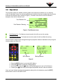
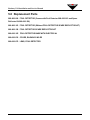
RADARAY XLi
INSTALLATION & SERVICE MANUAL
P/N 400-088-006
Revision A
ALL RIGHTS RESERVED
All rights to this Installation and Operation Guide are the property of AMF Bowling Products,
Inc., including the diagrams, figures, and technical specifications. Reproduction or
transmission of any of the material contained in this Guide is strictly forbidden without the
prior permission of AMF Bowling Products, Inc. All of the product information contained in this
manual was carefully prepared based on the latest information available and, to our
knowledge, was believed to be correct at the time of printing. However, this publication could
include inaccuracies or typographical errors, and AMF Bowling Products, Inc. cannot be held
responsible for inadvertent errors or omissions that may appear in this document. AMF
Bowling Products, Inc. reserves the right to revise and/or update this manual at any time
without obligation to notify any person or entity of such revision.
TRADEMARK NOTICES
All trademarks and trade names mentioned in this manual are the property of their respective
owners. AMF disclaims any proprietary interest in trademarks and/or trade names other than
their own.
DOCUMENT UPDATES
In the interest of continual product and services improvement, AMF reserves the right to
revise or update this manual at any time without obligation to notify any person or entity of
such revision. The document number and revision date below indicate the edition and printing
date of this manual.
Copyright © 2004 AMF Bowling Products, Inc.
Document Part No. 400-088-006
Issue Date: 10/22/04
AMF BOWLING PRODUCTS, INC.
8100 AMF Drive
Mechanicsville, Virginia 23111
Radaray XLi
Installation and Service Manual - P/N 400-088-006
Rev. A
Summary of Changes
Change No.
none
ECR No.
List of Effective Pages
Page
All
Change No.
Original
Effective Date
10/22/2004
CONTENTS
1.0
General Information ...................................................................... 1
2.0
Installation and Alignment Procedure ......................................... 3
2.1 Installation ............................................................................... 3
2.2 Alignment Procedure ................................................................ 4
2.3 Single Side Operation .............................................................. 4
3.0
Operation ........................................................................................ 5
4.0
Maintenance ................................................................................... 7
5.0
Replacement Parts ........................................................................ 9
Radaray XLi Installation and Service Manual
1.0 General Information
The Radaray XLi provides a means of detecting encroachment upon the foul line on a pair of lanes.
The unit employs two (2) retro-reflective photoeyes. All that is required externally are reflectors
mounted across the lanes from the Radaray unit. The Radaray XLi is designed to be used only with
the XLi Pinspotter Chassis.
The unit is powered by 12 VDC at .100 Ampere from the XLi Chassis. When a foul is detected (the
optical path between the unit and the external reflector is broken), an independent signal for that lane
is sent to the chassis telling it that a foul occurred. Also, a sinking 12 VDC signal is activated for 12
seconds which lights the LED for that lane (mounted in the control unit cover) and causes a beeper to
sound for approximately 1.5 seconds.
P/N 400-088-006
1
Revision A
Radaray XLi Installation and Service Manual
This page intentionally left blank.
P/N 400-088-006
2
Revision A
Radaray XLi Installation and Service Manual
2.0 Installation and Alignment Procedure
2.1
Installation
Foul Detector Chassis (088-000-163)
The Foul Detector Chassis mounts above the underlane track (Use alignment marks stamped on the
Radaray chassis). It should be positioned as square as possible with the lanes for ease of alignment
and proper operation. The sensor has two “bubble” lenses, one used to emit the light signal and one
to receive it.
Note - ABC/WIBC equipment specifications require that, “The beam of the foul detecting device shall
be set not more than 1/4 inch beyond the approach side of the foul line.” Be sure that the installation
of your Radaray unit complies with the ABC/WIBC specifications.
The installation sequence is as follows:
1. Mark the location of the three mounting holes using the Radaray chassis as a template. Drill
pilot holes as necessary for the three mounting screws. A typical pilot hole should be 5/32" in
diameter.
2. Plug the ten position RADARAY connector on the ball return cable (088-000-015) into the
receptacle on the back of the unit.
3. Secure the chassis with the three self-tapping #10 x 1" hex head screws provided.
4. Before installing the cover, install the reflector and complete the alignment procedure.
5. Install the cover. Secure each side using the two 1/4-20 x 1/2" screws provided.
Reflector Unit (088-000-128)
The reflector unit mounts at the end of the common lane division capping. The unit should be
positioned so that the center of the reflectors is in line with the approach edge of the foul line. The
installation sequence is as follows:
1. Mark the location of the two mounting holes (forward and rear) using the base as a template.
Then drill pilot holes as necessary for the two mounting screws. A typical pilot hole should be
5/32" in diameter.
2. Secure the reflector base with the two self-tapping #10 x 1" hex head screws.
3. Install the cover using the two 1/4-20 x 1/2" machine screws.
P/N 400-088-006
3
Revision A
Radaray XLi Installation and Service Manual
2.2
Alignment Procedure
The Foul Detector is prealigned at the factory. On installations where the mounting surface is level
and the foul detector is square to the lanes, additional alignment may not be necessary. In any event,
alignment should be verified after installation.
Each optical assembly has one axis of adjustment which is horizontal (left and right). It is only
necessary to slightly loosen the mounting screws to align the optics. The screws should not be
completely removed.
An orange indicator lamp (LED) is built in to the optical assembly and is used to indicate the proper
alignment of the optics. When poorly aligned, the LED will not be lit. If the alignment is close, the LED
will be blinking. At best alignment, the blinking will stop and the LED will show a solid light.
To align the optical assemblies, use the following procedure:
Make certain that there is a clear path between the foul detector optics and the retro-reflector
mounted in the housing across the lane from the unit.
1. Turn on the Radaray from the pinspotter chassis or handheld unit (See Section 3.0 Operation).
2. Remove the Radaray cover.
3. Loosen the two mounting screws slightly, allowing the optical assembly to rotate from side to
side. Rotate the assembly until the LED obtains a solid light. Secure the screws. The
horizontal alignment is now complete.
4. Replace the Radaray cover and test the unit to make sure that everything is still aligned.
Note - It is very unlikely that the vertical alignment will be incorrect. Apply some slight pressure on
either side of the sensor bracket to determine if it needs to be adjusted. Remember, vertical
adjustment should only be done if the horizontal alignment adjustments do not yield a solid light on
the LED. If the vertical alignment is not correct, carefully use a pair of needle nose pliers and slightly
bend the sensor bracket to tilt the sensor up or down as needed.
2.3
Single Side Operation
In an installation where only one detector is used (an odd number of lanes, for example), the foul
detector for the unused lane can be deactivated through the chassis using the same procedure as
mentioned in Section 3.0 Operation.
P/N 400-088-006
4
Revision A
Radaray XLi Installation and Service Manual
3.0 Operation
The pinspotter chassis is capable of showing when a lane has the foul detector on or in warning
mode. On the Main Screen, you will see symbols just to the left of the lane numbers that tell you what
mode the foul detectors are in (shown in Figure 1). If neither of the icons for the foul detector is
displayed, then the foul detector is off.
Foul Detector On
Foul Detector Warning
Figure 1, Foul Detector Icons
Foul Detector On - Foul lights are turned on and a foul will count on the scoring.
Foul Detector Warning - Foul lights are turned on and a foul will not affect the scoring.
The foul detector modes can be changed through the pinspotter chassis of handheld unit by using the
following steps (see Figure 2).
MCU Menus
Settings Menus
Figure 2
1.
2.
3.
4.
Press the [MCU] button to go into the MCU Menus.
Press the [Æ] button to select the Settings Menus.
Scroll down by using the [È] button until the flashing arrow is next to Foul Detector.
Pressing the [Æ] button will cycle through the possible choices for the foul detector.
Once you have finished selecting the appropriate setting for the foul detectors, press the [EXIT]
button twice to return to the Main Screen.
P/N 400-088-006
5
Revision A
Radaray XLi Installation and Service Manual
This page intentionally left blank.
P/N 400-088-006
6
Revision A
Radaray XLi Installation and Service Manual
4.0 Maintenance
The system is designed to operate properly with a significant amount of dust and dirt accumulation on
the optics. However, it is advisable to perform periodic cleaning of the reflector surfaces and optical
windows.
Note - IT IS RECOMMENDED THAT THE OPTICAL SURFACES BE COVERED DURING ANY
LANE MAINTENANCE THAT GENERATES LARGE AMOUNTS OF DUST AND DIRT OR ALLOWS
CHEMICALS TO SPLASH ABOUT.
Cleaning recommendations follow:
1. Use a clean non-abrasive cloth to gently wipe the face of the reflectors on the reflector unit
and the optics window on the chassis cover.
2. If gently wiping does not remove the dirt, as may be the case for grease or wax accumulation,
a mild soap (such as dishwashing liquid soap) and water solution may be used. First wash and
then gently wipe dry.
DO NOT USE ABRASIVE CLEANERS OR STRONG
SOLVENTS AS THEY MAY PERMANENTLY DAMAGE
THE SURFACES!
3. The black plastic covers may be cleaned with a protective cleaner such as ARMOR ALL, but
care should be taken to protect the optical windows as described above. For this reason, it is
recommended that the cleaner be sprayed on a non-abrasive rag and then the unit be gently
wiped clean.
ARMOR ALL is a registered trademark of Armor All Products Corporation.
P/N 400-088-006
7
Revision A
Radaray XLi Installation and Service Manual
This page intentionally left blank.
P/N 400-088-006
8
Revision A
Radaray XLi Installation and Service Manual
5.0 Replacement Parts
088-000-090 FOUL DETECTOR (Comes with Foul Detector 088-000-163 and Spare
Reflector Kit 088-000-128)
088-000-163 FOUL DETECTOR (Without FOUL DETECTOR SPARE REFLECTOR KIT)
088-000-128 FOUL DETECTOR SPARE REFLECTOR KIT
088-000-165 FOUL DETECTOR BASE WITH ELECTRICAL
088-000-074 COVER, RADARAY W/LED
088-000-079 LENS, FOUL DETECTOR
P/N 400-088-006
9
Revision A
Radaray XLi Installation and Service Manual
This page intentionally left blank.
P/N 400-088-006
10
Revision A