1
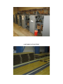
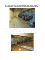
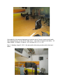
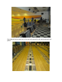
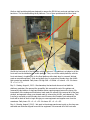
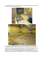
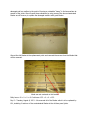
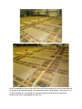
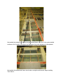
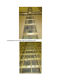
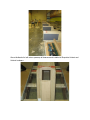
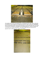
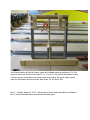
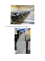
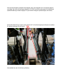
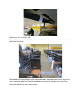
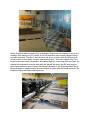
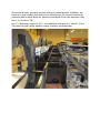
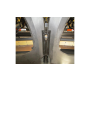
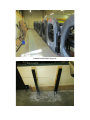
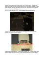
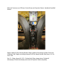
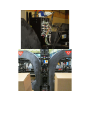
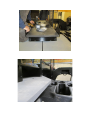
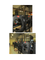
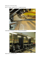
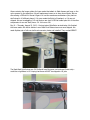
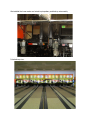
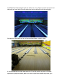
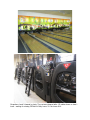
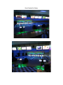
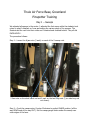
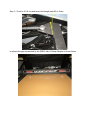
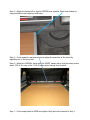
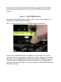
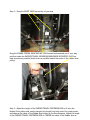
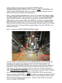
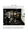
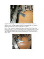
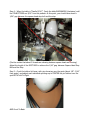
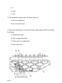
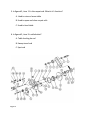
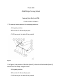
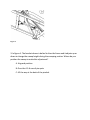
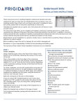
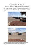
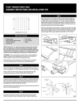
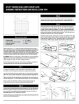
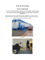
Thule Air Force Base
Thule, Greenland
8 Lanes – Remove Pinsetters, Scoring, Lanes, Powerlifts, and Foul Lights
and replace with New QAMF Pinspotters with CE Guards and Related
Equipment
Arrived at 9:00 AM local time. Went through customs, safety training, and security checks.
Visited bowling center and unloaded tools. Checked into Quarters. Toured and got supplies.
Daylight around the Clock - Barracks at 2:00 AM:
Apartment:
Before Photos:
LANE PANELS ACCLIMATIZING
Day 1 – Friday, August 2, 2013 – We removed the Pinsetter elevator deflectors, elevators,
return chutes, cushions, curtains, sweeps, and pits completely and swept backend floor clean.
We removed old masking units, foul lights, Options hoods and trays, loosened old Options
powerlifts ready for removal. Removed approach fill, scoring bowler’s terminals, Pinsetter
guards and catwalks, curtain wall scoring hardware, old cameras, and removed all old scoring
wiring. We separated Pinsetter front ends from a wiring standpoint – ready to remove.
We loaded all of the removed equipment on trucks for the Air Force to inventory and handle
final resting places for, as they choose. Daily hours – (all workers Contractor-Level skills) – 36
Highly Skilled + 0 Skilled + 0 Laborer = 36. Job Hours: 36 + 0 + 0 = 36.
Day 2 – Saturday, August 3, 2013 – We removed the old scoring monitors with a block and
tackle.
We restacked the lane panels out of the way, and removed the old caps/coverboards and
gutters.
We then build portable platforms designed to remove the GS-98 front ends and get them to the
back door. This involved building three platforms. Two of them portable and the other fixed.
We lift the front end off of the kickbacks with this jack-cart. This platform is a bridge to roll the
front end from the kickbacks to a mobile platform. Then, we roll the mobile platform, with the
front end aboard, via pallet jack, to the fixed platform at the back door for removal. Worked
great as we positioned lane 1 front end at back door for removal on Monday when the forklift
and operator are available. Daily hours: 36 High Skill + 0 Skilled + 0 Laborer = 36. Job hours:
72 + 0 + 0 = 72.
Day 3 – Sunday, August 4, 2013 – We cleaned-up the back end where we had built the
platforms yesterday. We removed the powerlifts. We removed the rest of the gutters and
removed the last section of single and double division capping support across the house. We
loosened all of the underground ball return track ready for removal. We removed all of the lane,
pindeck, and approach screw cover dowels ready to remove the old HPL, and cleaned up. That
is as far as we could go until Monday when we will remove the Pinsetter front ends and the
locals will be back at work to begin bringing our new equipment and supplies over from the
warehouse. Daily hours: 20 + 0 + 0 = 20. Job hours: 92 + 0 + 0 = 92.
Day 4 – Monday, August 5, 2013 – We went to the storage warehouse to pick up the chop-saw
and table-saw that was shipped here with the equipment. We removed all of the front ends
from the kickbacks. We then removed the kickbacks and pindecks (except for the one pindeck
we are using as our ramp to the back door).
We removed all of the ball accelerators and all of the underlane ball track. We removed the
powerlifts and old ball return trays, old scoring monitors and frames, and all other related
equipment to a staging spot behind the bowling center, and the Air Force hauled all of this old
equipment away. We removed all of the old lane panels and staged outside for pick-up
tomorrow. The center has a lot of Medex damage due to the extreme contraction of the lane
panels after they were installed. The Medex under many of the panel joints has been severely
damaged and has swollen to the point of forming a noticeable “hump” in the lane surface at
several of the joints. We will repair these situations by using some of the less contaminated
Medex we will remove, to replace the damaged sections with good Medex.
We cut the old Medex at the replacement point and removed the screws from the Medex that
will be removed.
Made saw cut centered on this leveler
Daily hours: 40 + 0 + 0 = 40. Job hours: 132 + 0 + 0 = 132.
Day 5 – Tuesday, August 6, 2013 – We removed all of the Medex which is to be replaced by
LSL, including 4’ sections of the contaminated Medex at the old lane panel joints.
All of the materials we need for the rest of this week was brought over from the warehouse and
we brought it all inside and staged. The pindeck areas were a total disaster. There weren’t two
of them built alike. So, we decided to rip everything above the stringers out, rebuild the
stringers where they are damaged and start over.
We figured what lumber we would need and complied a field cut-list and cut all the lumber we
would need. We rebuild the stringers where they were notched or damaged.
We began rebuilding the pindeck support from scratch.
We cut out and removed the 42” of approach Medex that is being replaced by LSL and cut LSL
to fit. Approach area LSL almost finished. Daily hours: 40. Job hours: 172.
Day 6 – Wednesday, August 7, 2013 – We rebuilt the pindeck areas with new support lumber.
Now all lanes are the same and support are consistent and level.
We installed the kickback shoring and painted Pindeck/Medex joint line on the newly installed
continuous 2x6. Installed Tail support and Mid-support at proper elevations for flat pindeck.
We installed all underlane ball return track under a stringline and secured. Began installing
Track Runner.
We shimmed all of the levelers that will be replaced by LSL.
We shimmed the Pindeck area for proper elevations and levelness and tested Lane 1 to confirm
that our shimming gauge block will set the pindeck at the correct elevation to accept a lane
panel. All good.
Daily hours: 40. Job hours: 212.
Day 7 – Thursday, August 8, 2013 – We finished the underlane ball track plastic runner. We
shimmed the levelers at the locations where we removed the 4’ sections of Medex due to
severe damage and swelling from the panel shrinkage, and cut-to-fit and installed good Medex
which we removed from the approach area that was fitted for new LSL.
We secured all of the approach LSL completely. We finished replacing all of the old pindeck area
support for flat finished pindecks and installed the new pindecks under a stringline to achieve a
straight and continuous 7-10 line across the center, for perfect Pinspotter installation.
We shimmed the pindecks flat, and for perfect elevation between last lane panel and front of
pindeck. We installed all of the single and double kickbacks exactly 6 ¼” behind the straight 710 line and painted the 7-10 line on top of kickbacks.
We cut kickbacks for ball return upsweep rail clearance and installed all Pinspotter Unistrut and
Unistrut hardware.
We installed all transition blocks and began installing flatgutters.
Daily hours: 40. Job Hours: 252.
Day 8 – Friday, August 9, 2013 – We finished installing all flatgutters to exact spec for the lane
involved. Each flatgutter custom cut.
We installed foul lines and routered dead flush on the approach side, using a piece of laminate
to provide the correct elevation on the approach side for the router to follow. We made gauge
block and shimmed lane side of the foul line to accept LSL plus the lane panel with a .030” drop
from foul line to finished lane. Shimmed all of the levelers under the 4’ sections of Medex that
we removed due to water contamination. We cut good Medex which was removed from
approach area to replace the bad 4’ sections and installed.
We installed the new LSL on the first 22’ of each lane where the old Medex was removed.
We started with a 10’ piece of LSL to stagger LSL joints vs. panel joints. We cleaned-up the
back end completely. All LSL has been installed and all of the 4’ bad sections of contaminated
Medex have been replaced with good Medex. Back ends are ready for Pinspotters.
We sized the double division at the downsweep and notched to accept downsweep coverboard
and allow clear ball return.
We reinstalled the single and double division at the foul line and Pinspotter which had been
removed for the approach and kickback work. Daily hours: 40. Job hours: 292.
Day 9 – Saturday, August 10, 2013 – We cleaned-up the entire front end, removing all trash
and old Medex to dumpster. We received the PBL crates from the warehouse and unloaded,
unpacked, and staged in proper places inside. We received most of the scoring equipment from
the warehouse. We finished securing all new PSL that was tacked in place yesterday. We
checked and shimmed all of the remaining Medex for flatness and any mating issues with PSL.
We ran all overhead wires to scoring monitors and ran Pinspotter MCU Home Run cable, and
installed MCU at front desk and tied wires neatly. We installed Pinspotter Ball Detect boxes at
kickback noses. We ran all underground cables: Four Cat5 (beige, red, blue, yellow) for Bowler’s
Terminal Touch screens, Foul, and Ball Lift. We must buy ground wire to go from touch screens
to 4HD Hub mounting frames and will run later. We ran both camera wires underground and
secured out of harm’s way ready to plug/wire into cameras. We re-installed all round gutters
except the foul line sections which must be left out for electricians to finish some electrical
work. We began building Scoring Monitor frames. Daily hours: 40. Job hours: 292.
Day 10 – Sunday, August 11, 2013 - We cut the front gutter sections to size but left out so that
the electricians can finish their work. We build a fixture to mount to a pallet jack for
transporting and setting Pinspotter front ends.
We finished building all Scoring Monitor frames and installed mounting brackets on TV’s. We
hung the frames and monitors and wired TV’s on 1-2 and 7-8. We need a taller ladder to hang
3-6 which we can get Monday when they are open and working. We are all caught up and
ready for Pinspotters tomorrow morning. Daily hours: 16. Job hours: 308.
Day 11 – Monday, August 12, 2013 – We brought-in the front ends and placed on Kickbacks.
Our 3rd-world homemade fixture pictured above worked great.
Two Front end catwalks damaged in shipment. Keith ordered two.
We removed all packing materials and shipping stops. We changed front end gearbox plugs to
vent plugs. We set front end frame heights to 18 15/16” at all four jackscrews of all tables and
squeezes table legs outward slightly to a point where all legs are spread slightly and evenly.
Spread & locked all legs on jack screws when 3/16” of foot showing beyond all jam nut washers
for perfect centering over pin spots.
We installed the rest of the Scoring Monitors.
Daily Hours: 40. Job Hours: 348.
Day 12 – Tuesday, August 13, 2013 – We received back ends from the warehouse and placed
behind the front ends.
We installed the Scoring Bowler’s touch-screen terminals. And drilled new whole in the floor to
run the wires for power and Com. We installed ground wire from curtain wall to odd Touch
Screen and jumpered to even touch screen.
We set Pinspotter tables to parallel 5/16” and flagged. Because we had centered so well on the
kickbacks, after setting to 5/16”-parallel, 6 of the 8 pinspotters were perfectly flagged without
any table movement. The other 2 were obviously set wrong at factory with all slot showing on
10-side of both of these tables. We took equal amounts from 7-side and 10-side to flag. Frontto-back was perfect on all 8 pinspotters. We replaced back end motor plugs with vent plugs. We
removed all components from even back ends and staged. We moved the PBL stop bumpers
and bumper brackets to top of frames. We sorted all hardware for the Pinspotter install. We set
back end heights in neighborhood of front end heights for easier back end install tomorrow. We
installed pit lights and began installing sweeps.
We removed all trash, cleaned-up the back parking lot outside back door completely, and
tooled-up to begin installing back ends to front ends tomorrow. GC personnel removed all
crates and skids to remote dump site. Received powerlifts ad CE kits from warehouse. Daily
hours: 40. Job Hours: 388.
Day 13 – Wednesday, August 14, 2013 – We installed the back ends 6 ½” behind 7-10 line.
They came out great- perfect elevation, mating, levelness, and straightness.
Installed end kickback Supports
We installed the scoring cameras. We hung plywood on the curtain wall for mounting our
scoring and other components. We installed 4HD Hubs and wired up pinspotter legs and down
from overhead.
We began installing the Options Powerlifts up front. We began pinspotter assembly. We
installed sweeps. We completed the install stroke of installing hotdogs and upsweep rails with
shimmed boomerangs. We completed the stroke of installing mousetraps, rutter drives,
shimmed ratchets, and adjusted-for-length lifter rods.
We began installing black tracks and behind that, began stroke of installing Tie Plates (old Vplates), spring straps, and PBLs and related belts and springs. We installed first section of round
gutters where the electricians have finished their wiring work, and shimmed for Foul Lights in
the process. Daily hours: 40. Job hours: 428.
Day 14 – Thursday, August 15, 2013 – Finished installing Options Powerlifts up front.
Prepared for Foul Unit install, notching gutters and planeing Division Support for an even
transition from Foul cover to first Coverboard.
Installed capping and coverboards. Finished installing all Black Tracks. Finished Pinspotter install
stroke of installing PBL’s, Spring Straps, Tie Plates (between back end motor mount brackets),
Belts and Tensioners and CE Power Control Boxes and Pinspotter Chassis. Installed all Light Ball
Sensors.
Began installing E-Stop Wireway Brackets. Began installing Downsweeps to Black Tracks and
Underlane Track. Began connecting wireways to CE Box support bracket. Daily hours: 40. Job
hours: 468.
Day 15 – Friday, August 16, 2013 – Finished the E-Stop wireway boxes. Finished all
downsweeps. Finished all wireways and wired all Pinspotter Chassis completely.
Installed all Pinspotter Tie-Down Plates.
Received all CE package components from the warehouse and unpacked and sorted.
WOW that’s a lot of stuff for 8 lanes!!!
Kevin flew home today. Bye “scoring guy” – great job and great to work with you!
Daily hours: 30. Job hours: 498.
Day 16 – Saturday, August 17, 2013 – We adjusted shuttles, set PBL heights, and secured
Optical Bin switch wires. We installed, leveled posts, shimmed for elevation, and centered
Distributors. We installed Orientor Pans. We centered, leveled, and secured lower end of Black
Track. We began installing CE Guards.
Daily hours: 30. Job hours: 528.
Day 17 – Sunday, August 18, 2013 – Installed ball detects.
Wired Options Powerlifts up front. Continued CE installation.
Daily hours: 22. Job hours: 550.
Day 18 – Monday, August 19, 2013 – Continued CE install. Changed location of door switches
from walkway side to pinspotter side. Installed rear CE guards.
Customer wanted PBL Guards installed even though CE does not call for this guard, so we
notched rear cage and installed and secured with a bolt on the stiffener.
Installed all front CE rails and dividers. Installed Mask Stanchions. Electricians began powering
Pinspotters.
Wired all E-Stop switched to CE Controller on Lane 2. We are waiting for replacement catwalks
to finish end lanes.
Figuring out the best way to route and tie-up CE switch wires, then we will wire the rest. Daily
Hours: 30. Job Hours: 580.
Day 19 – Tuesday, August 20, 2013 – We finished wiring E-Stop switches on lanes 2-7.
1 and 8 have been wired at the CE Power Controller, but we are waiting for the replacement
catwalks for 1 and 8 to be able to finish end kit CE installation. We replaced all wireway covers.
Electrician finished providing Pinspotter and logic power to all Pinspotters. We received the
balance of the masking unit components, and pins from the warehouse and staged. We put 20
pins in each Pinspotter. Electrician began installing power circuits for Mask lighting. We began
preparing Mask frames for installation. We removed cardboard protector from Pit Carpet,
cleaned pit area, and installed curtains and curtain protectors. We began installing the CE Light
Curtains (switch 7 is the only error we are getting anywhere – Light Curtain).
They were very easy to install and adjust. 1-4 are installed. Having all 10 E-Stops per pair
installed, we fired-up Lanes 1-4 (we taped switch mates to the 3 yet-to-be-installed switches on
Lane 1 so we could test 1-4). All came up fine. Lanes ran great, but guard positions, exact
spotting, sweeps, and Light Ball Sensors need adjusting (and I left 2 distributors a bit too high)
which I am leaving for the week of training, upcoming. We can run them fine for now. These
final adjustments will be great training for the students next week. Daily hours: 30. Job hours:
610.
Day 20 – Wednesday, August 21, 2013 – We finished the CE guards out to the masking unit
stanchions and finished the light curtains on 5-8.
We ran all pinspotters and all are good. There was a spot solenoid on 2 that shorted and blew
Chassis fuse. Replaced solenoid from spare parts. All of the large nuts that the distributor clutch
spring attaches to were loose. Tightened and re-tensioned clutch springs. All eight ran fine. We
left guard positions, final table pin-spotting adjustments, sweep adjustments, and light ball
sensors for the students to do in next week’s training. We wired back-light fixtures for upper
and lower Masks. We built all upper Masks and installed lights.
We installed scene and hung upper Mask units. We also built lower Mask units complete with
light fixtures.
We are missing the hanger plates for lower masks that attach to Mask frames and hang on the
nylon spacers on the stanchions. We will make some tomorrow to hang lower Masks. We are
also missing a CE End Kit. We can’t figure if it is at the warehouse somewhere (they had our
stuff stored in 10 different places), if it never made the flight to Greenland, or if it was not
shipped. We are investigating. It is odd that we are short a CE End Ladder plus ALL of the other
components for an end. Daily hours: 30. Job hours: 640.
Day 21 – Thursday, August 22, 2013 – Scoring trainer Mike Eaton arrived today. We finished
the lower masks. We had to fashion Lower Mask Pivot Plates since none were shipped. We
made 8 plates out of left-over ball track connector plates and installed. They worked GREAT!
The Mask Back-light fixtures are 220 Volt and have European cord ends and Power strip –
would be a nightmare in US. Hoping that these will NOT be shipped to US jobs.
We installed the lower masks and wired to pinspotters, and tied-up wires neatly.
It looked very nice.
Under Black light with back-lights off it also looked very nice. (Single rope-light-caps just arrived
today with new rope lights). We will install when they are delivered from the warehouse).
We cleaned-up completely and set out lane panels and began to tack in place.
All of the needed parts arrived today except the CE end kits, which may come on Monday.
Replacement pinspotter catwalks, New Front Desk computer and related components, rope
lights, single rope-light-capping… all arrived as scheduled. They will be delivered tomorrow from
warehouse. Pinspotter training begins tomorrow. Daily hours: 30. Job hours: 670.
Day 22 – Friday, August 23, 2013 – Betterley-routered all panel joints and re-sealed. Waxpapered all panel joints. Predrilled with Vix bit and secured panels with panel screws. Installed
the new Front Desk Computer with all accessories and ran solid copper home run. Reinitialized
4HD-CPUs. Daily hours: 20 (Lou training on Pinspotters). Job hours: 690. Pinspotter Training
hours: 8.
Day 23 – Saturday, August 24, 2013 – Ran Pinspotters for 2 hours with NO issues. We installed
all approach and cut/Betterley routered all fills and secured. Screwed-down all lanes and sealed
all joints except the last pine and pindeck joints. Will cut-in and seal last pine panel tomorrow.
Daily hours: 30. Job hours: 700.
Day 24 – Sunday, August 25, 2013 – We shimmed all approach. We cut in and Betterleyroutered the last pine panel to mate perfectly with both pindeck and second-to-last pine panel.
All came out fine. Finished with all panel cutting. No damage or mistakes. We doweled the first
two panels of all 8 lanes matching the Lane/dowel patterns. The dowels are invisible from the
foul line. We wax-papered, shimmed and sealed the final joints where the last pine panels were
installed today. Daily hours: 24. Job hours: 724.
Day 25 – Monday, August 26, 2013 – We finished all approach fill, cutting in trap doors in front
of Ball Returns. We installed all ball trays, hood shrouds, hoods, and extra storage racks. We
installed the face-board at start of approach – shimming and routering for perfect fit.
Installed maple starter blocks at round-gutter start. Pinspotter training continued - Day 2. Daily
hours: 28. Job hours: 752. Pinspotter Training Hours: 16.
Day 26 – Tuesday, August 27, 2013 – Installed Single Rope-Light Capping just received and
installed foul lights. Cleaned the center of all trash and waste. Pinspotter Training continued –
Day 3. Daily hours: 18. Job hours: 770. Pinspotter Training hours: 24.
Day 27 – Wednesday, August 28, 2013 – Installed rope lights and doweled the rest of the
lanes. Installed Camera Reflectors. Adjusted Camera ball detects, loaded Pinspotter default
parameters and scoped-in cameras. Daily hours: 20. Job hours: 790.
Day 28 – Thursday, August 29, 2013 – Finished-up odds and ends and cleaned-up completely.
Stripped and oiled lanes, and tested. Free Bowling tonight as a “ring-out” event prior to
Saturday’s Grand Opening. Keith will be staying here waiting for the missing CE End Kit, and to
check for proper function of all components.
AFTER PHOTOS:
Pinspotters 1 and 2 cleaned in photo. The rest were cleaned after. CE cables shown on lane 1
loose – waiting for missing CE End Kit. Daily hours: 20. Job hours: 810.
More Finished Job Photos
Thule Air Force Base, Greenland
Pinspotter Training
Day 1 – Sweeps
We adjusted all sweeps in the center. I adjusted the first sweep while the students took
notes on what I dictated, as I was performing the various steps of the process. The
Students did the rest from their notes and I coached and checked behind. They all did
EXCELLENTLY.
The procedure follows:
Step 1 – Loosen the 6 jam nuts (2 each) on each of the 3 sweep rods.
2 Jam nuts on the short travel rod and 2 each on the two long rods (7 pin side long rod
not shown)
Step 2 – Crank the sweep motor Counter-Clockwise to perfect GUARD position (all the
way DOWN and all the way OUT). Set the sweep gauge blocks under the sweep near
outer edges of the lane.
Loosen the bolt through the SLOT in the Triangular plate.
Hold the bolt and Panagraph Rod forward and tighten to set guard sweep height at the
size on the gauge.
Step 3 – Crank to 4-5-6 row and move the triangle plate UP or Down
to achieve the gap represented by the SMALL side of Sweep Gauges as shown below.
Step 4 – Adjust the sweep left or right to CENTER over pindeck. Gaps from pindeck to
sweep should be near equal on both sides.
Step 5 – Crank sweep to rearmost point and adjust the evenness of the travel by
adjusting one of the Long rods.
Step 6 – Adjust the OVERALL travel with the SHORT sweep rod so that the sweep covers
about 15% of the rear of the 7-8-9-10 spots when looking from Pindeck.
Step 7 – Crank sweep back to HOME and tighten the 6 jam nuts loosened in Step 1.
Run the sweep under power and adjust overall travel so the sweep travels rearward
PAST the reference lines behind the 7 and 10 spots, BUT SHORT of the end of the
Pindeck.
Day 2 – Light Ball Sensors
We adjusted all Light Ball Sensors and began Tables – half the tables complete. The
following is the Light Ball Sensor Procedure:
Step 1 – Install Light Ball Sensor unit CENTERED between the Kickbacks.
Be sure that the RUDDER ARM bisects the Rudder arm stop-bumper (Up and Down
adjustment) Shim the Light Ball Sensor FRAME at the TOP two attaching bolts to RAISE
the rudder arm or at the BOTTOM two frame attaching bolts to LOWER the rudder arm,
so that the rudder arm BISECTS the rudder arm stop bumpers on a 45 degree angle.
Adjust the rudder arm IN OR OUT of it’s housing to achieve a CENTERED PADDLE within
the ball door opening.
Be sure that the LIFTER height is about 1/8” above the ball door weldment:
Adjust the LIFTER height by shortening or lengthening the LIFTER ROD.
Step 2 – Snug the RESET CAMS up and out of your way
Snug the POWER STROKE INDUCING ARC CAM forward and centered out of your way,
and then make the RUDDER TRAVEL WIDENING/NARROWING ECCENTRIC PLATE as
least eccentric as possible (shaft as far as possible toward the center of the rudder drive
pulley).
Step 3 – Adjust the length of the RUDDER TRAVEL CENTERING ROD to fit onto the
Rudder Drive pulley stud, evenly changing the length from both ends. Run under power
and observe the travel of the Rudder Arm relative to the Stop Bumpers. Adjust the length
of the RUDDER TRAVEL CENTERING ROD to CENTER the travel of the Rudder Arm as
well as possible and tighten jam nuts. Adjust the RUDDER TRAVEL
WIDENING/NARROWING ECCENTRIC PLATE to achieve 1/16” of OVERTRAVEL of the
POWER STROKE INDUCING ARC CAM as the rudder arm dwells momentarily on each
rudder stop bumper, and tighten both securing nuts.
Step 4 – Stop the LBS when Rudder travel is on one of the travel-stop bumpers. Adjust
the POWER STROKE RESET CAM for that side to be within 1/32” of the POWER STROKE
CAM FOLLOWER. Repeat for the other side. Then tweak the POWER STROKE RESET
CAMS with a pry bar, to obtain BOTH a FULL RESET of the Power Stroke Cam Follower,
AND YET allow the rudder arm to fully reach it’s rudder stop bumper. THERE IS ONLY
ONE PLACE that the Reset Cams can be positioned that will achieve BOTH a FULL RESET
of the Power Stroke Cam Follower AND a complete Rudder Travel ALL THE WAY to the
Rudder stop bumper.
Step 5 – Position the POWER STROKE INDUCING ARC CAM
To within 1/8” and centered between the two POWER STROKE CAM FOLLOWERS. BE
CERTAIN THAT THE ARC CAM DOES NOT TOUCH EITHER POWER STROKE CAM
FOLLOWERS DURING ROUTINE MOTION. Run under power and inhibit the rudder arm
listening for a strong “CLICK” sound as the power stroke is induced. A change in the
angle of the Arc Cam may be needed to induce a solid “click” for BOTH odd and even
sides. YOU ARE NOT FINISHED until: 1. Overtravel of Arc Cam is 1/16” and fairly
even on both odd and even sides, 2. POWER STROKE RESET CAMS reset the power
stroke cam followers COMPLETELY – AND the rudder arm reaches and dwells on BOTH
rudder arm stop bumpers. 3. Arc Cam is VERY close to, but NOT touching either Power
Stroke Cam Follower during routine motion. 4. There is a solid “CLICK” as the power
stroke is induced on BOTH SIDES.
Day 3 – Tables
Step 1 – Crank the Table to the spotting position holding down the spot latch, so that
pins are delivered to cups and table goes all the way to the pindeck. The table is at it’s
lowest point when these three points are in a straight line.
Step 2 – Make the table PARALLEL to the pindeck by adjusting the Table Tie-Rods, so
that when measuring under the 1, 8, and 10 Pin button-head respot cell pivot bolts, all
three corner are THE SAME distance from the pindeck – PARALLEL to the pindeck.
Adjust the CLEVIS length, so that the table is 5/16” from the pindeck. We call this
PARALLEL 5/16”. The Table should be PARALLEL TO the pindeck AND 5/16” from the
pindeck. A bit higher than 5/16” OK. Lower than 5/16” not OK.
Step 3 – “Flag” the table by inserting table flags into the table at the 1, 7, and 10 pin
respot cell locations as shown below, and move the table as needed (one side at a time),
by loosening the 3 bolts on each side of the table, that connect the steel table to the
table weldments. Locate the table so that the table flags point to the center of the 1, 7,
and 10 spots.
Step 4 – When the table is “Parallel 5/16””, Crank the table BACKWARDS (clockwise) until
the PIN BOTTOMS are 5/16” from the pindeck. At this point, you should have about a
1/16” gap between the square-head stop bolt and the stop.
(First be certain that about 5 threads are showing between square head and housing).
Adjust the length of the SPOT ROD to achieve the 1/16” gap, between Square Head Stop
Bolt and the Stop.
Step 5 – Crank the table a bit lower, with pins hovering over the spots (about 1/8” -3/16”
from spots), and adjust each individual spotting cup to CENTER the pin bottom over the
spot BOTH Left-To-Right
AND Front-To-Back
Loosen BOTH TOP spotting cup bolts until cup is hanging freely. Tap the cup and block
evenly - right or left until centered. Choose ONE U-BOLT and tighten top nut of that Ubolt until the pin bottom is centered over the spot from front-to-back, then tighten lower
and upper nuts of that U-Bolt EQUALLY in small increments, to maintain the cups
centered-from-front-to-back location until the cup is secured in place by that one U-Bolt.
Then tighten the loose U-Bolt’s nuts in such a way as to MATCH THE NUMBER OF
THREADS showing beyond the TIGHTENED U-BOLT’S upper and lower nuts for even
pressure on the spotting cup. Repeat for all cups. Test under power and adjust individual
cups if one or a few cups are off spot. If ALL cups are good from front-to back but ALL
are a bit in front of or behind spots (by about the same amount) – then tweak SPOT ROD
to adjust ALL cups a bit forward or back.
We set all Guard positions for 1st and 2nd Guard on all pinspotters and recorded positions
in the manual. We covered the MCU (Manager’s Control Unit) at the front desk
completely.
We also covered Distributors. We totally covered the Distributor mechanics. We adjusted
all Distributors for about ¼” clearance between the Distributor’s front belt guard, and the
raised rib at the back of the Durabin. We checked all Distributors for free movement of
the Carriage Tubes between the Nylon Carriage Tube rollers, and disassembled ALL
Distributor Clutches, cleaned, reassembled, and re-tensioned clutch spring. Special
attention was paid, to begin a clutch cleaning procedure with the Distributor at the HeadPin position, and that the pinion gear was re-installed with alignment of the marked
pinion gear tooth and it’s corresponding marked tooth on the Distributor Cam. We also
Lubed Distributors.
We reviewed the entire Service Manual, covering all the adjustments we have made so
far, and where they can be found in the manual, as well as tomorrow’s PM pages, Parts
Drawings, Troubleshooting, Lubrication, Distributor Manual, MCU Manual, PBL Manual,
Chassis Manual, and all other Service Manual sections.
Day 4
We trained on Cameras. We adjusted all of the ball detects on the Q-Vision Cameras. We
loaded and sent Pinspotter Default Parameters, and scoped-in all cameras through
Conqueror. We removed and reinstalled a cushion and bounce board/carpet assembly.
We changed a Pinspotter chassis (testing spare) and loaded all MCU settings which we
have recorded in the Chassis Manual including Guard settings. We completely lubed
pinspotter front ends and ran. We adjusted all foul detectors and tested.
Day 5
We performed the entire PM schedule and cleaned Pinspotters. Students took the test. All
three students got “A” grades. Christian 97%, Rasmus 95%, Per 92%. Ring-out event
tonight so we are all returning. Free Bowling scheduled from 7-10 PM.
Test:
Thule AFB
Greenland
QAMF Edge Training School
Table and Front End
Circle correct answers
1. Table “flags” are used to do what?
A. Set table height
B. Spot pins
C. Center table over pindeck
2. At it’s lowest spotting position, table should be parallel to pindeck and how far
above the pindeck?
A. 1”
B. 5/16”
C. 1/8”
3. The solenoid fires right before the table is about to:
A. pick up standing pins
B. set a new rack of pins.
4. When the solenoid fires, it does three things. Which below is NOT one of those
three things:
A. Unblock the shuttle
B. Induce a long table stroke
C. Cause cups to turn downward
D. Open respot cells
Figure 1
5. In figure #1, item 11 is the respot rod. What is it’s function?
A. Used to raise or lower table
B. Used to open and close respot cells
C. Used to level table
6. In figure #1, item 9 is called what?
A. Table leveling tie rod
B. Sweep travel rod
C. Spot rod
Figure 2
7. Figure 2 is of what component?
A. Table drive assembly
B. Table motor assembly
C. Table torque tube assembly
8. In Figure #2, item 4 is called the clevis. What is it’s function.
A. Used to raise or lower table
B. Used to open and close respot cells
C. Used to level table
9. Table adjustments can be done in any order.
A. True
B. False
10. When spotting, the pin bottoms should strike the pindeck:
A. Slightly toe-first
B. Flat
C. Slightly heel-first
11. The length of which rod determines when the spotting cups shift rearward,
releasing pins in the spotting motion:
A. Spot rod
B. Respot rod
C. Table tie-rod
12. The length of which rod determines when the respot cells open and close:
A. Spot rod
B. Respot rod
C. Table tie-rod
13. The length of which rods determines the levelness of the table:
A. Spot rod
B. Respot rod
C. Table tie-rod
14. The spotting cups are all individually adjustable.
A. True
B. False
15. When changing a spotting cup, the table should be positioned:
A. As high as it will go
B. As low as it will go
C. Pin bottoms hovered over spots
16. How many respot cells are on a pinspotter?
A. 2
B. 6
C. 10
17. How many different respot cell types are on a pinspotter?
A. 2
B. 6
C. 10
18. How many respot cells on a pinspotter have carburetor links attached to
them?
A. 2
B. 6
C. 10
19. Respot cells should hold a pin just above the top red stripe/Crown on the
pin.
A. True
B. False
20. During which cycle are respot cells called upon to operate?
A. Strike cycle
B. 1st ball cycle
C. Foul cycle
Thule AFB
QAMF Edge Training School
Sweep, Back End, and PBL
Circle correct answers
1. The sweeps lowest point in the sweeping motion is:
A. At guard position
B. Over the 4-5-6 row of pin spots
C. All the way at the back of the pindeck
Figure 3
2. In Figure 3, the position of the bolt (item 6) in the slot of the bracket (item 8)
determines the sweep’s height where?
A. At guard position
B. Over the 4-5-6 row of pin spots
C. All the way at the back of the pindeck
Figure 4
3. In figure 4. The bracket shown is bolted to the side-frame and it adjusts up or
down to change the sweep height during the sweeping motion. Where do you
position the sweep to make this adjustment?
A. At guard position
B. Over the 4-5-6 row of pin spots
C. All the way at the back of the pindeck
Figure 5
4. Item 48 in figure 5 is the sweep travel rod. This rod’s length determines how far
the sweep travels rearward. Where do you position the sweep to make this
adjustment?
A. At guard position
B. Over the 4-5-6 row of pin spots
C. All the way at the back of the pindeck
5. When the sweep is at guard position, it should be:
A. 1 1/8” – 1 3/16” above the lane surface
B. About 3/16” above the pindeck
C. Even with the rear tailplank reference marks
6. When the sweep is over the 4-5-6 row of pin spots, it should be:
A. 1 1/8” – 1 3/16” above the lane surface
B. About 3/16” above the pindeck
C. Even with the rear tailplank reference marks
7. When the sweep is running under power, it’s rear-most position should be:
A. 1 1/8” – 1 3/16” above the lane surface
B. About 3/16” above the pindeck
C. Even with the rear tailplank reference marks
8. The sweep is adjustable from right-to-left over the pindeck.
A. True
B. False
9. It is possible to adjust the travel of the 7-pin side of the sweep and the 10-pin
side of the sweep independently.
A. True
B. False
10. If a sweep-table interlock occurs because a pin gets trapped between the
sweep and the flat-gutter, this usually is an indication of what?
A. Sweep is traveling too far rearward
B. Sweep is not traveling far enough rearward
11. The assembly that stops the ball as the ball leaves the pindeck is called:
A. The carpet
B. The bounce plate
C. The cushion
12. The item which conveys the pins back to the pin elevator is called:
A. The carpet
B. The bounce plate
C. The cushion
13. The “hidden” assembly which funnels the ball toward the ball exit is called:
A. The carpet
B. The bounce plate
C. The cushion
14. The back end motor drives three pinspotter components. They are the PBL
system, the pin elevator, and what?
A. The sweep
B. The table
C. The distributor
Figure 6
Figure 6 is the light ball sensor assembly. Locate items 19, 25, 39, and 52. Each
item does one of the four choices below.
15. Item 19 does what?
A. Centers the rudder/paddle travel
B. Induces a “power stroke”
C. Resets the power stroke cam follower to “normal stroke”
D. Narrows or widens the rudder/paddle travel
16. Item 25 does what?
A. Centers the rudder/paddle travel
B. Induces a “power stroke”
C. Resets the power stroke cam follower to “normal stroke”
D. Narrows or widens the rudder/paddle travel
17. Changing the length of item 39 does what?
A. Centers the rudder/paddle travel
B. Induces a “power stroke”
C. Resets the power stroke cam follower to “normal stroke”
D. Narrows or widens the rudder/paddle travel
18. Adjusting item 52 does what?
A. Centers the rudder/paddle travel
B. Induces a “power stroke”
C. Resets the power stroke cam follower to “normal stroke”
D. Narrows or widens the rudder/paddle travel
19. The same belt which drives the carpet, drives the PBL system.
A. True
B. False