1
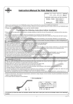
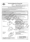
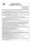
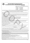
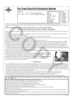
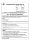
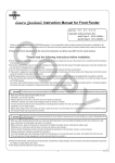
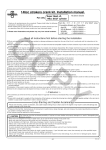
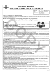
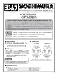
Instruction Manual for ST-3 Super Head Cylinder Kit
Item No.
:01−04−1004
CO
:Ape, Ape100, XR50 Motard, and XR100 Motard
Specification :Compatible with a motorcycle equipped with a TAKEGAWA’s ST-3 Super Head
Fitting
Thank you for purchasing one of our TAKEGAWA's products.
These products are a cylinder and a piston kits for our Stage-3 super head.
We have designed the cylinder with an aluminum oil passage. So you can install an oil cooler. Moreover, we have also designed the piston to be light in
weight, and given molybdenum coating to the skirt for better comformability.
Please strictly follow the following instructions in installing and using the kit.
Please read the following before starting the installation
○ This kit alone cannot function on its own. So, you are required to purchase the special cylinder head and the recommended parts.
○ We do not take any responsibility for any accident or damage whatsoever arising from the use of the kit not in conformity with the instructions in the manual.
○ We shall be held free from any kind of warranty whatsoever of products other than this product if the glitch takes place on the other products than this
one after the installation and use of this product.
○ For the purpose of using this kit in Ape50 and XR50 Motard, our TAKEGAWA-made Stage-3 super head and stroke-up crankshaft kit are necessary.
○ This kit is for exclusive use with our TAKEGAWA-made Stage-3 super head.
○ In case this kit is to be used in Ape50 and XR50 Motard, the crankcase needs to be processed in the portion where a sleeve is to be attached. For the
details and enquiries, please consult with your local specialist shop handling internal combustion products or a motorcycle dealer.
○ The processing of the crankcase requires engine removal and mounting, crankcase disassembly, and other work. Please do the work correctly referring
to a HONDA genuine service manual for your vehicle. In addtion, you need to prepare gaskets and the like for the assembly, which please purchase separately.
○ Please be informed that we shall be held harmless against any claim against us whatsoever arising out of use of the products in closed course competition.
○ This kit is intended for closed course competition purposes only. So, take note that it is prohibited to drive your motorcycle on a public road after the installation of this kit. Drive your motorcycle at a legal speed, abiding by the laws.
PY
The following show the envisioned possibility of injuries to human bodies and property damage as a result of disregarding the
CAUTION following cautions.
○ This kit is intended for closed course competition purposes only. So, take note that it is prohibited to drive your motorcycle on a public road after the
installation of this kit. Drive your motorcycle at a legal speed, abiding by the laws.
○ Make sure the engine and muffler are completely cool at below 35 degrees C before starting the installation. (Otherwise, you will burn yourself.)
○ Do the installation with right tools. (Otherwise, breakage of parts or injuries to yourself may take place.)
○ As some products and frames have sharp edges or protruding portions, please work with your hands protected.
(Otherwise, you will suffer injuries.)
The following show the envisioned possibility of human death or serious injuries to human bodies as a result of disregarding the
WARNING following cautions.
○ Those who are technically unskilled or inexperienced are required not to do the work.
(Improper installation because of insufficient skill and knowledge could lead to parts breakage and subsequently to accidents.)
○ Always use new piston pin circlips, gaskets and packing. The worn or damaged parts may break the parts, leading to accidents.
○ Before doing work, make sure your motorcycle is secure on level ground for safety's sake.
(Otherwise, your motorcycle could overturn and injure you while you are working.) ○ If you find damaged parts when checking and performing maintenance of your motorcycle, do not use these parts any longer, and replace them with
new ones. (The continued use of these damaged parts as they are could lead to accidents.)
○ Always start the engine in a well-ventilated place, and do not turn on the engine in an airtight place.
(Otherwise, you will suffer from carbon monoxide poisoning.)
○ Before riding, always check every section for slack in parts like screws. If you find slack ones, screw them securely up to the specified torque.
(Or improper torque may cause parts to come off, leading to accidents.)
○When you notice something abnormal with your motorcycle while riding, immediately stop riding and park your motorcyle in a safe place to check what
has gone wrong. (Otherwise, the abnormality could lead to accidents.)
○ As gasoline is highly flammable, never place it close to fire. Make sure that nothing flammable is near the gasoline. (Otherwise, it may cause a fire.)
○ Check or carry out maintenance of your motorcycle correctly according to the procedures in the instruction manual or service manual.
(Improper checking or maintenance could lead to accidents.)
○ Never use any other parts than those specified by us. (The use of the unspecified parts may lead to parts breakage and consequent accidents)
○ Always use a torque wrench to screw bolts and nuts tight and securely to the specified torque.
(Otherwise, these parts may get damaged or fall off, resulting in accidents.)
○ Since vaporized accumulation of gasoline is at the high risk of explosion, work in a well-ventilated place.
○ Be sure to always use premium unleaded petrol.
◎ Please be informed that the product specifications, design and prices are subject to change without prior notice.
◎ Please be informed that we do not accept any complaint filed with us against any technical trouble caused by the combined use of our products with
other manufacturers' products unspecified by us.
◎ This manual should be retained for future reference.
-A1-
Aug./22/’
06
∼ Kit Contents ∼
1
2
CO
4
5
8
9
3
7
6
A
4
3
5
2
PY
B
8
No.
1
2
3
4
5
6
7
8
9
Part Name
Aluminum Cylinder COMP.
Piston
Pinston Ring Set
Piston Pin
Piston Pin Circlip
Cylinder Head Gasket
Cylinder Gasket
Aluminum Sealing Washer
Oil Plug Bolt
No.
Item No.
A 01-02-2702
B 01-13-022
C 00-01-0052
7
6
Qty
1
1
1
1
2
1
1
2
2
C
Exhaust pipe gasket
Repair Part
12100-KN4-T00-C
13109-KSJ-T01
01-15-017
13111-KN4-T01
In packs of
1
1
1
1
12251-GEY-T30
1
00-07-0010
90145-GEY-T00
10
1
Description
Piston Kit
Gasket Kit B
Piston Pin Circlip Kit
※Please note that in ordering repair parts, be sure to quote the Repair Part Item No. Otherwise, we may not be able to accept your orders.
There are some parts, however, for which we are not in a position to accept your order in just the quantity to be used.
In this case, please take them in the quantity packed.
Co.,Ltd.
3-5-16 Nishikiorihigashi Tondabayashi Osaka Japan
-A2-
TEL : 81-721-25-1357 FAX : 81-721-24-5059 URL : http://www.takegawa.co.jp
Aug./22/’
06
∼ Cylinder Installation Instructions ∼
☆ Processing to crankcase:
◇In case of installation to a 50cc motorcycle, disassemble the
engine, referring to the service ◇ With reference to the figure below,
fix piston rings with a letter N facing
upward.
Color of the piston rings:
Top: Gold
2nd.: Black
CO
manual, and consult your
specialist shop for the
processing.
◇ Install the crankcase, referring to
the Honda’s service manual and
the installation instructions for a
stroke-up crankshaft kit.
Note : Be sure to tighten to the specified torque.
◇ Insert the cam chain tensioner into
the supplied cylinder, and hang the
hook of the spring on the cylinder.
(In the case of a 50cc motorcycle,
attach the cam chain tensioner
supplied in the crank kit.)
◇Apply engine oil to the entire side
surface of the piston and piston
rings.
ring
トTop
ップリング
120°
120°
120°
◇Install the piston to the cylinder with care so the piston ring-end
gaps do not get out of alignment.
Second
ring
セカンドリ
ング
エキスパンダー
Expander
60°
サイドrail
レール
Side
60°
Note : Always use the new
gaskets.
☆Cylinder Installation
◇ Apply engine oil to the piston pin holes.
◇ Remove the gasket scraps
thoroughly with a scraper or a
cutter knife.
Note : Be careful not to give scratches to the clamp face.
◇Place the cam chain tensioner so the tip of the rod will be nearly at the
same level as the clamp face.
Fix it with an adjusting bolt and tighten a locking nut.
◇ Once the piston is completely in
the cylinder, pass the cam chain
through the cylinder and install the
cylinder to the crankcase.
PY
Rod tip
◇Apply engine oil to the piston pin hole
of the con’rod.
◇ With a cutter knife, cut off the gasket squeezing out of the
crankcase sleeve hole so the sleeve hole surface becomes level.
Left crankcase
◇ Apply engine oil or molybdenum solution to the piston pin, and fix the
piston so EX mark on the upper
surface of the piston faces the
exhaust side.
Right crankcase
◇Remove the waste cloth used to clog
the holes.
◇Degrease the mating surfaces of the
crankcase and the cylinder with
thinner or the like.
◇ Fix the cam chain guide, aligning
its end with the grooves on the crankcase and its protrusion with
the grooves on the cylinder.
(In the case of a 50cc motorcyle,
install the cam chain guide
supplied in the crank kit.)
Protrusion
Tip
◇ Attach two dowel pins and a
cylinder gasket to the crankcase.
カムチェ
Cam ーンガイド
chain
guide
シリ
ンダー
Cylinder
After correction
EX
クランクケース
Crankcase
◇Fix a supplied piston pin circlip to
one of the piston pin holes.
◇ Fix the supplied piston pin circlip.
※ Arrange the position of the ring-end
gap of the piston pin circlip not to be
on the notch.
◇ Apply engine oil to the inside of the
cylinder, and then spread the oil evenly.
-B1-
◇ Install the cylinder head,
referring to the cylinder head
installation instructions.
Aug./22/’
06
Reference Value List for Cylinder and Piston
Cylinder
Piston
Description
Distortion
Internal Diameter
φ57
External Diameter (9 mm from the lower edge of the skirt)
Internal Diameter of Pin Hole
External Diameter of Piston Pin
Clearance of Piston Ring-End Gap
Top
2nd
Oil
Clearance between Cylinder and Piston
Clearance between Piston and Pin
CO
Stock
57.000∼57.020 mm
56.970∼56.995 mm
14.002∼14.008 mm
13.994∼14.000 mm
0.15∼0.38 mm
0.20∼0.45 mm
0.20∼0.70 mm
0.002∼0.014 mm
Service Limit
0.05 mm
57.095 mm
56.95 mm
14.03 mm
13.98 mm
0.50 mm
0.50 mm
0.90 mm
0.10 mm
0.05 mm
Remarks
Replace
Replace
Replace
Replace
Replace
Replace
Replace
Replace
Replace
Replace
○ Inspection of Cylinder:
・Check the inside of the cylinder for wear and damage
・Measure and take note of the internal diameters of the cylinder at 6 positions; at the piston pin angle and at the right angle to it (X-Y) each at
upper, middle and lower parts.
Treat the measured largest value as its internal diameter.
∴ If the diameter is larger than 57.095 mm, replace the cylinder.
Figure out the clearance between cylinder and piston.
PY
IN
Top
Y
EX
X
Middle
Bottom
○ Inspection of Piston:
・Clear the piston of the remaining carbon residue. ・Fit a piston ring into the piston, and measure the clearance between
the piston ring and ring groove with a thickness gauge, with a piston
ring being inserted into the ring groove. ∴ If the clearance is larger than 0.17 mm, replace the piston.
・Check the outside of the piston for the damage.
・Measure the external diameter of the piston at the specified place at
the bottom edge of the piston skirt at the right angle to the piston holes.
∴If the diameter is smaller than 56.95 mm, replace the piston.
・Measure the internal diameter of the piston pin hole.
∴ If the diameter is larger than 14.03 mm, replace the piston. ・Figure out the clearance between the piston and piston pin. ○Inspection of Piston Ring:
・Insert each piston ring into the cylinder from the bottom. And measure
the clearance of the end gap with a thickness gause.
∴Service limit: If the clerance is more than 0.5 mm at top and 2nd, or
more than 0.9 mm at oil, change the piston ring.
-C1-
Aug./22/’
06
∼ About boring process of a crankcase ∼
Installation of the provided cylinder to Ape50 and XR50 requires crankcase processing.
●To those who have the crankcase boring processed by a specialist shop:
CO
・Bore the crankcase till it is 61.4 mm in diameter and 25.5 mm in depth with crankcase gaskets put in between.
・And in processing the crankcase, take care to keep the walls of a dowel pin hole and an oil passage hole as thick as possible. Over-processing will result
in hardness decrease and poor oil lubrication.
25±0.
1 28±0.
1
Dowel pin hole
Dowel pin hole
● Cautions:
1
27±0.
Gasket
mm
1.4
er 6
t
e
Diam
mm
5.5
th 2
p
e
D
PY
1
27±0.
・Please note that processing of the crankcase will thin the wall thinkness, leading to strength degradation.
Co.,Ltd.
3-5-16 Nishikiorihigashi Tondabayashi Osaka Japan
TEL : 81-721-25-1357 FAX : 81-721-24-5059
URL : http://www.takegawa.co.jp
Apr./09/’
12