1
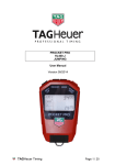
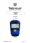
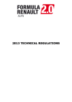
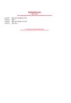
RESEARCH&DEVELOPMENT OF AMERICA, INC.
5420 DANIELS STREET STE A, CHINO CA., 91710 · (800) 634-9166 · (909) 628-4722 · FACSIMILE (909) 591-2198
www.yoshimura-rd.com
ST-R CAMSHAFT SET
SUZUKI RM-Z450
Part No. 700XX219210
CLOSED COURSE COMPETITION ONLY AND IS NOT INTENDED FOR STREET USE
The product that you are purchasing is designed and intended for closed course competition use only and
is labeled as such, i.e. Yoshimura “RACE SERIES”. Yoshimura RACE SERIES products are neither
designed nor intended for use on PUBLIC ROADS or LAND. Such use is prohibited by Federal and State
regulations.
This product is only designed for the application listed above. DO NOT install on any other applications not
specified.
Yoshimura is not liable for any damages due to abuse, misuse, improper installation and/or modifications.
Installation should be done by a qualified technician.
DANGER
Indicates a potential hazard that could result in death, injury or engine breakdown.
CAUTION
Indicates a potential hazard that could result in motorcycle damage.
REFERENCE
Indicates special information for simplified installation.
Applicable Model
Specifications
SUZUKI : RM-Z450 2015
DO NOT use for any other models.
INTAKE
EXHAUST
9.4mm
MAX LIFT
L.C. 110.0
8.8mm
MAX LIFT
L.C. 105.0
BTDC
ABDC
15.0
55.0
1mm
1mm
Open
Close
DURATION
250.0 / 1mm
BBDC
ATDC
58.5
28.5
1mm
1mm
Open
Close
DURATION
267.0 / 1mm
Tappet Clearance
Tappet Clearance
0.12mm
0.20mm
Kit Contents
No.
1
2
4
5
Part No.
21921-CSAI-00**
21921-CSAE-00
INST KIT
17029
Description
Yoshimura Intake Camshaft (w/shims)
Yoshimura Exhaust Camshaft
Instruction Kit
Yoshimura Decal
Qty
1
1
1
1
** Install two 0.5 mm spring seat shims (1.0 mm total) to
maintain proper tension.
DANGER
The valve spring seat shims must be installed under the
INTAKE valve spring seat with the correct numbers.
* The profiles above are designed specifications.
There may be small variances from measured numbers.
Optional Accessories
MX Tuner ...................................................................... [Part No. 431-185-0010]
Head Gasket (T=0.40mm) ............................................ [Part No. 0000A-E8110-141]
FI Indicator Light Assembly ........................................... [Part No. 36380-28H00]
Battery Lead Wire ......................................................... [Part No. 36890-28H00]
1
Installation Steps
Component removal and installation must be done in accordance with the SUZUKI Factory Service Manual.
Please refer to you SUZUKI Factory Service Manual for removal and installation procedures.
Inspecting The Items
Follow the service manual and thoroughly inspect related parts and replace if necessary.
DANGER
Check and replace each part thoroughly.
Installing the Camshaft and Sprocket
DANGER
The intake camshaft and the sprocket are assembled when delivered. However, if sprocket
bolts are loosened or removed follow the steps below to assemble and adjust the valve timing
as it is designed.
Adjust the top of the cam and the punched
marks on the sprocket as shown in Figure 1.
Adjust bolt-hole on camshaft as shown in
Figure 2.
Tighten the cam sprocket bolts and torque to
25 Nm (2.5 kg-m, 19 ft-lbs).
REFERENCE
For proper clearance between piston and intake valve, the intake cam sprocket should be
installed with the valve timing retard as Figure 2 shows.
Installing the Camshaft and Sprocket
Check to make sure that the piston is at T.D.C.
Follow the SUZUKI Factory Service Manual and install the exhaust camshaft and intake camshaft.
REFERENCE
The punch mark on the intake came
procket is located just below the
surface of the cylinder head.
Auto Decompression
The auto decompression components are used with this product. Follow the Suzuki Factory Service Manual to
remove from the stock camshaft. Install the stock decompression components to the ST-R exhaust camshaft.
Measure and Adjust Tappet Clearance
Specification (when the engine is cold)
INTAKE: 0.10 – 0.14mm
CAUTION
2
EXHAUST: 0.18 – 0.22mm
Check that the tappet clearance is within the specified range. Adjust if necessary.
To prevent burns and scratches, apply oil on top of the cam.
Fill the tappet oil pool of the cylinder head with oil.
Measuring and Adjusting the Valve Timing
DANGER
Both the intake and exhaust camshafts are delivered with the designed lobe center.
It is required to measure it by adjusting the valve timing when installing.
Note: The intake camshaft is supplied with an adjustable cam sprocket.
DANGER
Thread lock (Thread Lock 1342 – Suzuki P/N: 99000-32050) must be applied to the cam
sprocket bolts. Torque cam sprocket bolts to 25 Nm (2.5 kg-m, 19 ft-lb).
Valve Timing
This product allows you to change the engine characteristics by adjusting intake valve timing.
CAUTION
When the valve timing is changed, the piston-valve clearance will also change.
In some cases, there is insufficient piston-valve clearance after the valve timing has been
changed depending on the engine specification.
Note: The piston-valve clearance is a higher priority over the valve timing.
After Installation
• Fill engine oil to specified level. Use oil grade equivalent to or higher than API-SG.
• To reduce the friction on the engine, remove the spark plug and crank the engine.
• Follow the service manual to check the oil level. Add oil as needed.
• Start the engine and check for oil leaks. Let engine run until the oil temperature reaches operating temperature.
To maintain oil pressure during engine warm up, maintain engine speed between 2,000 ~ 3,000 RPM.
• For the first 30 minutes, open less than 1/4 of the throttle. After 30 minutes to 1 hour, open less than 1/2 of the throttle.
• After the break-in period, measure and adjust the tappet clearance and check for any abnormal noise.
• To maintain oil pressure during engine operation, maintain engine speed above 5,000 RPM.
CAUTION
During the break-in period, do not ride aggressively (sudden start and acceleration).
CAUTION
After installing this product, adjust the fuel volume using the MX Tuner.
[Part No. 431-185-0010]
Quality control is implemented to all the products. If, however, any failure was found,
please notify Yoshimura R&D, USA through the selling dealer. Necessary technical service or
replacement will be made. Due to on going improvement, the specifications and prices of the
products are subjected to be changed without notice.
YOSHIMURA R&D, USA
5420 Daniels Street , STE A
Chino, CA 91710
Phone (800) 634-9166
Fax (909) 591-2198
http://www.yoshimura-rd.com
3