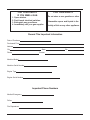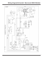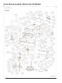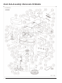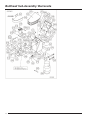
1
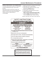
Operator’s Manual
Propane Stripping Machine
For all Barracuda Models
Failure to read and understand this manual
before operating this machine or performing service on this machine may result in injury to the
operator or nearby personnel or result in damage
to the machine or nearby property. Each operator
must be trained in the operation of this machine
before being allowed to use it. Contact Amano
Pioneer Eclipse Customer Service at
1-800-367-3550 or 1-336-372-8080 or an
authorized Amano Pioneer Eclipse Distributor to
inquire about training or to request a replacement
manual.
La falta de leer y de entender este manual antes
de usar esta máquina o de realizar servicio en
esta máquina puede dar lugar a lesión al operador
o al personal próximo o a resultado en daño a la
máquina o propiedad próxima. Cada operador
debe ser
entrenado en la operación de esta
máquina antes de ser permitido utilizarla. Ponerse
en contacto con el servicio de Amano Pioneer
Eclipse 1-800-367-3550 o 1-336-372-8080 o un
distribuidor autorizado por Amano Pioneer Eclipse
para investigar sobre el entrenamiento o para
solicitar un manual.
Manquer de lire et de comprendre ce manuel
d'utilisation avant l'utilisation de cette machine ou
avant faire de maintenance sur la machine peut
être résulter en blessure à l'opérateur ou au
personnel proche ou peut endommagé la machine
ou la propriété proche. Chaque utilisateur doit être
entraîné dans l'opération de cette polisseuse
avant l'utilisation. Veuillez contacter le service
àpres-vente de Amano Pioneer Eclipse à
1-800-367-3550 ou 1-336-372-8080 et/ou un
distributeur de Amano Pioneer Eclipse pour vous
renseigner concernant l'entraînement ou pour
obtenir un autre manuel d'utilisation.
FOR YOUR SAFETY
FOR YOUR SAFETY
IF YOU SMELL GAS:
1.
2.
3.
4.
Open window.
Don't touch electrical switches.
Extinguish any open flame.
Immediately call your gas supplier.
Do not store or use gasoline or other
flammable vapors and liquids in the
vicinity of this or any other appliance.
Record This Important Information
Date of Purchase
Purchased From
Address
City
Phone
State
Contact
Machine Model
Machine Serial Number
Engine Type
Engine Serial Number
Important Phone Numbers
Medical Emergency
Police
Fire Department
Zip
Safe Operating Practices
z Allow only qualified and trained personnel to
z
z
z
z
z
z
z
z
z
z
z
z
operate equipment.
Follow maintenance and operating instructions.
Keep accurate records of maintenance and
service in the provided log book.
Remember, routine maintenance NOW will
prevent a breakdown LATER.
Check oil level before starting.
Keep nuts and bolts tightened and hose
connections snug.
Refer to engine manufacturer’s service manual
or contact Amano Pioneer Eclipse for engine
repairs or adjustments not listed in this manual.
Never alter or reconstruct the fuel system. To
do so may be dangerous and will void the
factory warranty.
Use UL, CTC/DOT listed Safe-Fill™
cylinders supplied by Amano Pioneer Eclipse.
Be careful not to cross thread the Rego
coupling on the fuel cylinder.
Store the fuel cylinder outside away from heat
and direct sunlight.
Have the machine serviced by a certified
technician, including an emission check, every
three (3) months.
Before attempting any service on the machine,
turn the ignition switch “OFF” and remove the
key to avoid accidental start-up.
WARNING: Operate in a well ventilated area.
(Catalytic mufflers need to warm up before they are
effective. Failure to do so may cause nausea or
carbon monoxide poisoning.)
WARNING: Keep hands and feet clear of rotating
brush! Inspect brushes regularly. (A fractured brush
may result in loose fragments causing injury.)
WARNING: Do not engage clutch to rotate brushes
unless brushes are in contact with floor. This can
damage the brushes and/or the deck.
WARNING: Do not operate machine on a dry floor,
as this may result in damage to the brush and/or the
deck.
WARNING: Failure to follow the instructions and
warnings appearing in this operating manual or on
machine labels may result in serious injury to the
person using the machine and possibly to other
persons and property.
NOTE: This machine is manufactured for
commercial use only.
Propane powered floor strippers are designed and
manufactured for commercial floor stripping only.
These machines are designed to strip most modern
types of floors including composition tile, stone,
marble, terrazzo, concrete and resilient floor covering.
Even though NFPA 58 8-4.5 says ...”these machines
shall be permitted to be used in buildings frequented
by the public, including the times when such buildings
are occupied by the public,” Amano Pioneer Eclipse
suggests usage when occupancy of a given work
area is minimal.
These machines should not be used:
z in nursing homes, hospitals, day-care centers,
etc.
z by unqualified or untrained personnel.
z unless properly maintained and adjusted.
z on areas with obstructions such as thresholds,
floor outlet boxes, etc.
z in areas where loose tile or other objects are
present.
z in rooms without proper ventilation.
These machines should not be left running
unattended.
CAUTION: Do not allow the stripper to operate
without moving the machine. It may damage the
floor covering.
PROPOSITION 65 WARNING
Battery posts, terminals, and related accessories
contain lead and lead compounds, chemicals
known to the State of California to cause cancer
and reproductive harm. Wash hands after handling.
Contents
Machine Specifications . . . . . . . . . . . . . . . . . . . . . . . . . . . . . . . . . . . . . . . . . . . . . . . . . . . . . . . . .2
Propane Machine Safety
Purpose . . . . . . . . . . . . . . . . . . . . . . . . . . . . . . . . . . . . . . . . . . . . . . . . . . . . . . . . . . . . . . . . . .3
Refueling and Storage of Fuel Cylinders . . . . . . . . . . . . . . . . . . . . . . . . . . . . . . . . . . . . . . . . . .3
Safety in Engineering . . . . . . . . . . . . . . . . . . . . . . . . . . . . . . . . . . . . . . . . . . . . . . . . . . . . . . . .3
Use and Care . . . . . . . . . . . . . . . . . . . . . . . . . . . . . . . . . . . . . . . . . . . . . . . . . . . . . . . . . . . . . .3
Canadian Safety Regulations . . . . . . . . . . . . . . . . . . . . . . . . . . . . . . . . . . . . . . . . . . . . . . . . . .3
Operator-Ear Sound Pressure Level . . . . . . . . . . . . . . . . . . . . . . . . . . . . . . . . . . . . . . . . . . . . .4
Hand-Arm Vibration . . . . . . . . . . . . . . . . . . . . . . . . . . . . . . . . . . . . . . . . . . . . . . . . . . . . . . . . .4
Machine Preparation
Adding Oil . . . . . . . . . . . . . . . . . . . . . . . . . . . . . . . . . . . . . . . . . . . . . . . . . . . . . . . . . . . . . . . .5
Connecting Battery . . . . . . . . . . . . . . . . . . . . . . . . . . . . . . . . . . . . . . . . . . . . . . . . . . . . . . . . . .5
Adjusting the Handle and Rok Bak™ . . . . . . . . . . . . . . . . . . . . . . . . . . . . . . . . . . . . . . . . . . . .5
Filling the Fuel Cylinder . . . . . . . . . . . . . . . . . . . . . . . . . . . . . . . . . . . . . . . . . . . . . . . . . . . . . .5
Installing the Fuel Cylinder . . . . . . . . . . . . . . . . . . . . . . . . . . . . . . . . . . . . . . . . . . . . . . . . . . . .5
Operating Instructions
Starting Instructions . . . . . . . . . . . . . . . . . . . . . . . . . . . . . . . . . . . . . . . . . . . . . . . . . . . . . . . . .6
Operation . . . . . . . . . . . . . . . . . . . . . . . . . . . . . . . . . . . . . . . . . . . . . . . . . . . . . . . . . . . . . . . . .6
Idling and Stopping the Machine . . . . . . . . . . . . . . . . . . . . . . . . . . . . . . . . . . . . . . . . . . . . . . . .6
Lifting / Lowering the Machine . . . . . . . . . . . . . . . . . . . . . . . . . . . . . . . . . . . . . . . . . . . . . . . . .7
Installing and Changing Brushes . . . . . . . . . . . . . . . . . . . . . . . . . . . . . . . . . . . . . . . . . . . . . . .7
Using the Transport Cart . . . . . . . . . . . . . . . . . . . . . . . . . . . . . . . . . . . . . . . . . . . . . . . . . . . . .8
Storage . . . . . . . . . . . . . . . . . . . . . . . . . . . . . . . . . . . . . . . . . . . . . . . . . . . . . . . . . . . . . . . . . .9
Repacking . . . . . . . . . . . . . . . . . . . . . . . . . . . . . . . . . . . . . . . . . . . . . . . . . . . . . . . . . . . . . . . .9
Transportation . . . . . . . . . . . . . . . . . . . . . . . . . . . . . . . . . . . . . . . . . . . . . . . . . . . . . . . . . . . . .9
Proper Lifting of Machine . . . . . . . . . . . . . . . . . . . . . . . . . . . . . . . . . . . . . . . . . . . . . . . . . . . . .9
Scheduled Maintenance . . . . . . . . . . . . . . . . . . . . . . . . . . . . . . . . . . . . . . . . . . . . . . . . . . . . . .10
General Maintenance Procedures
Fuel System . . . . . . . . . . . . . . . . . . . . . . . . . . . . . . . . . . . . . . . . . . . . . . . . . . . . . . . . . . . . . .11
Adjusting the Regulator . . . . . . . . . . . . . . . . . . . . . . . . . . . . . . . . . . . . . . . . . . . . . . . . .11
Engine Dust Filter . . . . . . . . . . . . . . . . . . . . . . . . . . . . . . . . . . . . . . . . . . . . . . . . . . . . . .11
Carburetor Air Filter . . . . . . . . . . . . . . . . . . . . . . . . . . . . . . . . . . . . . . . . . . . . . . . . . . . .11
Fuel Hose and Connections . . . . . . . . . . . . . . . . . . . . . . . . . . . . . . . . . . . . . . . . . . . . . .11
Engine Maintenance . . . . . . . . . . . . . . . . . . . . . . . . . . . . . . . . . . . . . . . . . . . . . . . . . . . . . . . .11
Cooling Fins . . . . . . . . . . . . . . . . . . . . . . . . . . . . . . . . . . . . . . . . . . . . . . . . . . . . . . . . . .11
Head Bolts . . . . . . . . . . . . . . . . . . . . . . . . . . . . . . . . . . . . . . . . . . . . . . . . . . . . . . . . . . 11
Changing Oil . . . . . . . . . . . . . . . . . . . . . . . . . . . . . . . . . . . . . . . . . . . . . . . . . . . . . . . . .11
Belt Maintenance . . . . . . . . . . . . . . . . . . . . . . . . . . . . . . . . . . . . . . . . . . . . . . . . . . . . . . . . . .12
Adjusting the Handle . . . . . . . . . . . . . . . . . . . . . . . . . . . . . . . . . . . . . . . . . . . . . . . . . . . . . . .12
Battery Maintenance and Replacement . . . . . . . . . . . . . . . . . . . . . . . . . . . . . . . . . . . . . . . . . .13
Brush Maintenance . . . . . . . . . . . . . . . . . . . . . . . . . . . . . . . . . . . . . . . . . . . . . . . . . . . . . . . .14
Tire Maintenance . . . . . . . . . . . . . . . . . . . . . . . . . . . . . . . . . . . . . . . . . . . . . . . . . . . . . . . . . .14
Gear Box Maintenance . . . . . . . . . . . . . . . . . . . . . . . . . . . . . . . . . . . . . . . . . . . . . . . . . . . . . .14
Splash Guard Maintenance . . . . . . . . . . . . . . . . . . . . . . . . . . . . . . . . . . . . . . . . . . . . . . . . . . .14
Machine Cleaning . . . . . . . . . . . . . . . . . . . . . . . . . . . . . . . . . . . . . . . . . . . . . . . . . . . . . . . . . .14
Troubleshooting . . . . . . . . . . . . . . . . . . . . . . . . . . . . . . . . . . . . . . . . . . . . . . . . . . . . . . . . . . . . . .15
Machine Drawings and Parts Lists
Safe-Fill Cylinder Head Layout . . . . . . . . . . . . . . . . . . . . . . . . . . . . . . . . . . . . . . . . . . . . . . . .17
Dash Panel: KWA/E Models . . . . . . . . . . . . . . . . . . . . . . . . . . . . . . . . . . . . . . . . . . . . . . . . . .18
Dash Panel: KWC/E Models . . . . . . . . . . . . . . . . . . . . . . . . . . . . . . . . . . . . . . . . . . . . . . . . . .19
Wiring Diagram/Schematic: KWA/E Models . . . . . . . . . . . . . . . . . . . . . . . . . . . . . . . . . . . . . .20
Wiring Diagram/Schematic: KWC/E Models . . . . . . . . . . . . . . . . . . . . . . . . . . . . . . . . . . . . . .21
Deck Sub-Assembly and Parts List
BA30KWA, BA30KWAE, BA30KWC, BA30KWCE . . . . . . . . . . . . . . . . . . . . . . . . . . . . . .22
BA38KWA, BA38KWAE, BA38KWC, BA38KWCE . . . . . . . . . . . . . . . . . . . . . . . . . . . . . .24
Bulkhead Sub-Assembly and Parts List . . . . . . . . . . . . . . . . . . . . . . . . . . . . . . . . . . . . . . . . .26
Regulator Assembly . . . . . . . . . . . . . . . . . . . . . . . . . . . . . . . . . . . . . . . . . . . . . . . . . . . . . . . .28
Kawasaki Engine Sub-Assembly and Parts List . . . . . . . . . . . . . . . . . . . . . . . . . . . . . . . . . . .30
Transport Cart Assembly and Parts List . . . . . . . . . . . . . . . . . . . . . . . . . . . . . . . . . . . . . . . . .32
Specifications
BA30KWA(E)/KWC(E)
BA38KWA(E)/KWC(E)
Brush Size
2 x 16” (40,6 cm)
Brush Size
2 x 20” (51 cm)
Brush Speed
325 RPM
Brush Speed
325 RPM
Width
32” (81,3 cm)
Width
40” (101,6 cm)
Length
62” (158 cm)
Length
64” (162,6 cm)
Engine
Kawasaki 17 HP
Engine
Kawasaki 17 HP
Starting
12 V Battery
Starting
12 V Battery
Weight
280 lbs. (127 kg)
Weight
335 lbs. (161 kg)
Handle
Bent Tube with Bail
Handle
Bent Tube with Bail
Deck
Cast Aluminum
Deck
Cast Aluminum
Vibration
Less than 2.5 m/s
Vibration
Less than 2.5 m/s
Sound Level
87 dB(A)
Sound Level
87 dB(A)
2
Propane Machine Safety
noise, we strongly recommend that hearing protection
be worn by the operator.
Purpose
The accepted demand for and use of propane
powered floor machines underscores the need for
responsible manufacturers and users to stress the
importance of safety. This manual is designed to
provide the information you need to ensure proper
and safe use of propane powered floor machines.
Use and Care
All machines manufactured by Amano Pioneer
Eclipse come with a detailed Operator’s Manual.
Safety dictates that before using any new equipment,
it is important to read and understand the Operator’s
Manual. We strongly recommend this practice.
In addition, we recommend operators of propane
powered floor machines complete a program of
training and certification for the safe operation of this
equipment.
Canadian Safety Regulations
1. A sign indicating “NO SMOKING” shall be
permanently displayed at the storage area. The
sign shall be in accordance with the sign required
in Clause 10.12.3 of CAN/CGA-B149.2-M91,
Propane Installation Code.
2. When the cylinder is attached to the floor
maintenance machine for use, the operator shall
not leave the unit unattended except for short
periods of time such as rest stops, washroom or
meal stops.
3. The requirements of 1.10.1 (e) and (g) do not
apply in industrial buildings.
4. A floor maintenance machine shall only be used in
buildings:
a) provided with continuous mechanical ventilation
that removes the products of combustion to the
outdoors of not less than 300 CFM for each
10,000 Btu-hr input or fraction thereof.
b) provided with natural ventilation of not less
than 300 CFM for each 10,000 Btu-hr input or
fraction thereof, based on a maximum of one
quarter air exchange per hour for the net
building volume.
5. The owner of a floor maintenance machine shall
ensure that the operator has participated in a
course authorized by the manufacturer of the unit
on the safe handling of propane and the safe
operation of the machine.
6. The owner of a floor maintenance machine shall
ensure that the unit is maintained in accordance
with the manufacturer’s recommended
maintenance procedures in a safe operating
condition and the owner shall maintain a record of
the maintenance for a period of two years.
7. Before transporting a floor maintenance machine,
the cylinder shall be securely fastened with the
system valve closed, and the cylinder shall be
located in a well ventilated space.
Refueling and Storage of Fuel
Cylinders
Propane cylinders should be filled only by an
authorized propane dealer. When not in use, they
should always be stored outside in an upright position
in a secure, tamper-proof, steel mesh storage cabinet.
This cabinet may be located next to the building but
with at least five feet (1.5 m) of space between the
cabinet and the nearest building opening (door or
window).
The National Fire Protection Association (NFPA)
Standard for Storage and Handling of LP Gas is the
appropriate authority for safe propane use. A copy of
this publication is available through the National Fire
Protection Association in Quincy, Massachusetts
(1-800-344-3555).
Safety in Engineering
Amano Pioneer Eclipse engineers and manufactures
machines utilizing UL (Underwriters Laboratories) and
CGA (Canadian Gas Association) approved
components where possible. When a tag or tags
bearing the CE and/or CGA insignia is/are affixed to
the machine, it indicates that the entire machine has
been researched, tested, and is listed by one or both
organizations as having met all of their safety criteria.
In some cases, the tag will be affixed to a particular
component. This means that only the component is
listed. Component recognition for the following parts
is important: fuel cylinders, couplings, regulators, and
fuel lines. We strongly recommend that you use only
machines meeting the above minimum requirements.
Even though propane powered floor machines
manufactured by Amano Pioneer Eclipse meet the
OSHA Time Weighted Average (TWA) standard for
Test for Operator-Ear Sound
3
Propane Machine Safety
Pressure Level
Amano Pioneer Eclipse measures and rates the
operator-ear sound pressure level for hand-guided floor
treatment and floor cleaning machines for industrial use.
All tests are performed in accordance with European
Machinery Directive (98/37/EC).
z Outdoor test area consists of a flat open space
free from effects of signboards, buildings or
hillsides for at least 15m (50 ft) from the center of
the test surface. Indoor tests are conducted in a
semi-anechoic or sound deadening room.
z The test surface is a single sheet of floor covering
at least 1 m (3.3 ft) wider and longer than the
equipment being tested. In order to not affect the
sound reading, the observer taking readings is at
least 2 m (6.6 ft.) from the equipment being
tested, or standing directly behind the operator.
z All machines are tested while stationary and
centered on the test surface. With the traction
drive in neutral (where applicable) the test is
conducted with the machine at maximum engine
or motor speed as specified by the manufacturer.
z The operator is located in the normal operating
position with the microphone or meter supported
independent of the machine, 1,68 m (66 in) above
the test surface, 25 cm (10 in) to the right and left
centerline of the operator’s position, and 20 cm (8
in) to the rearmost point of the handle, with the
handle in the most forward position.
z The sound level meter is observed for a minimum
of 5 seconds or until a stabilized reading is
obtained. The maximum repeatable sound level
observed during the test at each microphone
position is recorded and documented.
Test for Hand-Arm Vibration at the
4
Grip Surface of Hand-Guided
Machinery
Amano Pioneer Eclipse measures and rates the
vibration at the machine-hand contact surface of handguided machines that are provided with handles in
accordance with European Machinery Directive
(98/37/EC).
z The Test area consists of a flat open floor area
that allows the machine to be operated normally.
z The transducer is mounted firmly at a point
halfway along the length of the handle where the
handle would normally be held.
z Machines are tested while stationary, with all
mechanisms necessary for the equipment to
perform its intended functions engaged and the
traction drive in neutral (if applicable). The
machine will be tested at maximum engine or
motor speed as specified by the manufacturer of
the subject machine.
z The measurements are recorded from the
dominant axis.
Machine Preparation
Adding Oil
Filling the Safe-Fill™ Fuel Cylinder
When the machine is shipped by overland freight,
the correct amount of oil is in the engine. Air freight
shipments require the machine to be shipped without
oil.
Amano Pioneer Eclipse uses the 20 lb. capacity
aluminum Safe-Fill cylinder which meets the DOT
4E240
standards. These cylinders are also listed by UL
Filling should be done ONLY by a qualified propane
dealer. FILL THROUGH THE SERVICE VALVE
ONLY. (See page 13) A properly filled cylinder should
not exceed 80% of the rated capacity.
The machine is also shipped with the battery
disconnected.
When filling a “dry” machine or changing oil, for the
Kawasaki engine add no more than 1.5 quarts
(1,4 L) when not changing the oil filter, or 1 3/4 US
quarts (1,8 L) when the oil filter is changed, then
check the dip stick in the fill cap. Add oil if necessary
but DO NOT OVERFILL! ALWAYS CHECK OIL
BEFORE USING THE MACHINE. Refer to the
engine operator’s manual. IMPORTANT: When
checking oil on Kawasaki models, remove oil filler cap
and clean dipstick with clean cloth, then insert dipstick
into tube without screwing in. Then check oil level.
ALWAYS make sure the machine is sitting level
when checking oil.
DO NOT attempt Safe-Fill cylinder repair. Return the
cylinder to your propane dealer if repair is necessary.
Please note that DOT regulations prohibit shipping of
cylinders after the cylinder has been filled with
propane.
Installing the Safe-Fill Fuel Cylinder
Strap the Safe-Fill cylinder in place. Tighten the
adjustable straps securely. Connect the fuel hose
coupling to the service valve by turning to the right
(clockwise). HAND TIGHTEN ONLY. Make sure
coupling is not cross threaded and check for leakage
by noting any propane odors immediately after
cylinder is connected. (It is sometimes easier to install
if the connection to the service valve is made before
strapping the cylinder in place.)
Connecting the Battery
1. Connect the RED positive battery cable FIRST.
2. Connect the BLACK negative battery cable LAST.
Adjusting the Handle and Rok Bak
TO REMOVE THE SAFE-FILL CYLINDER, reverse
above procedure. Always connect or change
cylinders in a well ventilated area.
The stripper handle adjusts for comfort and optimum
control. Height may be changed to suit the individual
operator. The handle may also be adjusted to an
upright position to allow the stripper to be rocked
back for easy brush changing and maintenance.
(See page 9)
5
Operating Instructions
warning is being signaled. If the carbon monoxide
in the exhaust is approaching an elevated level
the YELLOW alert light will flash, indicating
service is needed. The machine will continue to
operate safely in this mode, but should be
serviced as soon as possible. If the carbon
monoxide levels exceed a pre-set service level,
the RED LED service light will start flashing. The
machine will shut down after the RED light has
flashed continuously for one minute.
Starting Instructions
1. Check oil (engine and gearbox) and fuel levels.
2. Check and clean engine air filter. NEVER RUN
CONTINUOUSLY FOR MORE THAN 1 HOUR
WITHOUT CLEANING OR CHANGING ENGINE
DUST FILTER. (See “Scheduled Maintenance”)
3. Check carburetor air filter. Change if necessary.
(See “Scheduled Maintenance”)
4. Turn propane service valve counterclockwise to
open. NOTE: ALWAYS OPEN SLOWLY TO
ALLOW PRESSURE TO EQUALIZE IN HOSES.
OPENING QUICKLY MAY CAUSE THE FLOW
CHECK VALVE TO ENGAGE, LIMITING FUEL
FLOW.
5. Leaving the bail throttle at idle, engage starter by
turning the key-switch to the starting position for
up to 5 seconds. If the machine fails to start, let
the ignition switch return to the run position (Do
not turn off). Wait approximately 5 seconds and
try again for another 5 seconds. (NOTE: Do not
engage starter for more than 10 seconds. Allow a
60 second cool-down period for each 10 second
start-up cycle.)
6. SAFE SENSE® ONLY: After engine starts, the
YELLOW alert light will flash for a 3 minute
warm-up cycle of the SAFE SENSE system. (The
machine may be operated during this warm-up
period.) After the warm-up cycle, the alert light will
go out. None of the SAFE SENSE lights will be
illuminated as long as the machine is running
safely.
WARNING! Catalytic mufflers require a few
minutes to warm up before effectively removing
harmful emissions. Make sure of proper
ventilation during this warm-up period!
It is recommended to start stripping on the right side
of the aisle, turn and come back down the aisle in the
opposite direction, overlapping the previous path
slightly. Continue this pattern until the floor area to be
stripped has been covered with the last pass being on
the right side of the machine.
Idling and Stopping the Machine
If for any reason the machine needs to idle for a short
period of time (less than 3 minutes), simply release
the bail handle.
SAFE SENSE ONLY: The SAFE SENSE system
will not allow the engine to idle unnecessarily.
After 4 minutes the Tilt/Idle LED will start flashing.
After another minute, the engine will shut down.
To stop the engine, close the service valve on the fuel
cylinder by turning it clockwise. (The engine will stop
when the fuel in the lines is used up).
Operation
After engine has started, pull the bail throttle to
operating speed and begin to move the machine
forward slowly. The clutch will engage automatically
at a preset speed.
CAUTION! DO NOT RUN THE STRIPPER
WITHOUT MOVING THE MACHINE. IF THE
MACHINE IS ALLOWED TO RUN IN ONE SPOT
DAMAGE TO THE FLOOR MAY OCCUR.
To stop stripping, release the bail handle.
SAFE SENSE ONLY: NOTE: This stripper is
equipped with the SAFE SENSE emission monitoring
system and catalytic muffler.
Upon starting the engine, the YELLOW SAFE
SENSE LED light will flash for 3 minutes during a
warm-up period. After that, it will be off unless a
6
Operating Instructions
Lifting / Lowering the Machine
To lift the machine:
1. Remove the handle from the transport
cart by loosening the knurled nut under
the handle. Remove the pull pin from
under the handle and pull the handle
outward.
2. With engine OFF and in the operating position, move
the transport arm on the front of the deck to an
outward position by removing the pull pin and
rotating the arm. Reinsert the pin to lock the arm in
the outward position.
3. Remove the knurled knot from the transport handle.
Insert the handle upside down up through the bottom
of the machine’s transport arm pivot hole. The small
locating pin on the handle must be aligned with the
small slot in the transport arm. Place the knurled nut
on top of the transport arm and handle stud and
hand tighten.
4. Move the machine handle to its Rok Bak position.
(See page 12). Using the handle on the front of the
machine, lift the machine to a full upright position.
NOTE: The barracuda stripping machine is heavy
and may require two people to lift or lower the
machine safely.
5. To lower the machine, repeat steps 1 - 4 in reverse.
Installing and Changing Brushes
To remove brushes:
1. With engine OFF and handle in the Rok Bak position
(See page 12), lift the machine into a full upright
position as described in “Lifting / Lowering the
Machine”.
2. While facing the brushes from the front of the
machine, turn the brush on the right counterclockwise with a quick motion and pull the brush
towards you. Turn the brush on the left clockwise
with a quick motion and pull the brush towards you.
3. The machine can now be lowered to the floor and
the handle returned to its operating position. The
brushes will not be flattened during storage or
transportation.
To install brushes:
1. With engine OFF and handle in the Rok Bak position
(See page 12), lift the machine into a full upright
position as described in “Lifting / Lowering the
Machine”.
2. While facing the machine from the front, place the
brush on the right into the slots and turn clockwise
with a quick motion. Make sure the brush snaps into
place. Place the brush on the left into the slots and
turn counter clockwise with a quick motion. Make
sure the brush snaps into place.
3. The machine can now be lowered to the floor and
the handle returned to its operating position.
7
Operating Instructions
Using the Transport Cart
This stripper comes equipped with a transport cart for moving the machine.
8
Operating Instructions
Storage
Only authorized, trained personnel should have access to propane cylinders and machines.
1. Remove propane fuel cylinder when not in use and store it outside in a storage cage in accordance with
NFPA Section 5 or Subsection 9.5.2 of CAN/CGA B149.2. Do not release or bleed propane inside the
building.
Please consult your local Fire Marshal to ensure that you are in compliance with local fire codes.
2. Store machine away from objects that may fall and damage it.
3. Never store machine or fuel cylinders near an open flame or heat producing devices.
4. Make sure machine is cleaned properly before
storing.
5. Never store machine with cylinders installed, or store spare cylinders in an enclosed van or trailer.
Repacking
1. Use shipping and package information attached to packing slip to repack machine.
2. Store machine in a dry location. Temperature should not exceed 50° C.
Transportation
When transporting a propane powered floor machine with the fuel cylinder installed, the cylinder should be securely
fastened with the service valve closed and the burnisher should be secured in the vehicle. Any propane fuel
cylinders not installed should be securely fastened to avoid movement and damage. The service valves should be
closed. Never store machines with cylinders installed, or store spare cylinders in an enclosed van or trailer. It is a
good practice to check propane cylinders for overfilling before transporting them. If overfilled, correct before
loading them in the vehicle by venting the excess propane outside in a safe area using the fixed liquid level gauge.
Proper Lifting of Machine
The machine should be lifted properly by attaching two (2) lifting hooks under the front of the deck and two (2) lifting
hooks around the lowest portion of the handle.
9
Scheduled Maintenance
Following proper scheduled maintenance procedures will provide years of uninterrupted service.
1.
2.
3.
4.
5.
6.
7.
Perform daily or after each use.
Refer to “General Maintenance Procedures.”
These items should be serviced by an authorized Amano Pioneer Eclipse Service Center.
Refer to Engine Manufacturer’s Owner’s Manual for recommended replacement.
Always enter maintenance performed in Service Log Book.
Routine Maintenance
Refer to Engine Service Manual.
10
General Maintenance Procedures
solution around all the connections while the
service valve is turned ON and the fuel system
is pressurized.
b. Fixing Leaking Joints
1) Uncouple bad joint and clean it. Then apply
pipe sealing compound (Loc-Tite Pipe Sealant
with Teflon or equivalent) to the clean joint.
2) Recouple the joint finger tight plus 1/2 turn.
3) Recheck for leaks using soapy water
solution. Watch for bubbles at the joint with
the fuel cylinder service valve turned on
and the fuel system pressurized.
Fuel System
The fuel system works from vacuum created by the
engine running. Turning the fuel cylinder service valve
ON pressurizes the system for flow to the carburetor
once the engine starts to crank.
Adjusting the Regulator
NOTE: The regulator and carburetor have been
factory preset and should not require any
modification. Only Amano Pioneer Eclipse authorized
personnel, trained and certified in propane systems,
should modify or adjust the system or its setting.
Engine Maintenance
N.F.P.A. 58 8-1.4 states, “In the interest of safety,
each person engaged in installing, repairing, filling, or
otherwise servicing an LP-Gas engine fuel system
shall be properly trained in the necessary
procedures.”
Cooling Fin Maintenance
a. Remove the blower housing and other cooling
shrouds.
b. Clean the cooling fins as necessary using
compressed air or pressure washer.
c. Reinstall all housings and shrouds.
Engine Dust Filter
The engine dust filter should be cleaned each hour
and after each use by shaking out the dust and then
rinsing with mild detergent. Squeeze out the excess
water (do not wring). Allow the filter to air dry. Failure
to maintain a clean engine filter will cause the
engine to overheat. Also, it may cause the
exhaust emissions to elevate to harmful levels.
Head Bolt Maintenance
Refer to Engine Manufacturer’s Service Manual.
Changing the oil
a. Run engine for 5 minutes to warm oil, then stop
the engine by closing the fuel service valve,
allowing the engine to stop by itself.
SAFE SENSE ONLY: NOTE: Must be
running above 2150 RPM or SAFE SENSE
will shut the engine down.
b. Locate the oil drain pipe located on the right
side of the machine.
c. Remove the cap by turning it counterclockwise
with a wrench.
d. Allow oil to drain completely into the receptacle.
Carburetor Air Filter
a. Loosen toggle clamps on each side of the air
cleaner cover.
b. Remove foam pre-cleaner and paper filter
element.
c. Clean foam pre-cleaner using the same procedure
as #2 above.
d. Clean filter seal, making sure no dust is allowed in
the carburetor inlet.
e. Inspect paper element. Replace if dirty, bent or
damaged.
f. Install the clean paper element, pre-cleaner and air
filter cover. Reclamp.
e. Replace the cap by turning clockwise.
f. Remove oil fill cap. Slowly add no more than 1
1/2 quarts (1,4 L) of motor oil when not
changing the oil filter, or 1 3/4 quarts (1,8 L)
when the oil filter is changed. Refer to engine
Owner’s Manual for recommended oil.
g. Check oil level with dip stick in oil fill cap. Add
additional oil if necessary.
h. Replace fill cap. Hand tighten only.
SAFE SENSE ONLY: NOTE: Failure to service the
carburetor air cleaner may produce excessive
carbon monoxide emissions and cause the SAFE
SENSE system to shut the engine down.
Fuel Hose and Connections
DO NOT OVERFILL AND NEVER RUN ENGINE
LOW ON OIL!
a. Inspection
1) Inspect hoses for abrasions and other signs of
wear; replace all worn or damaged hoses.
2) Check for gas leaks by spreading soapy water
IMPORTANT: ALWAYS MAKE SURE THE MACHINE
IS SITTING LEVEL WHEN CHECKING OIL.
11
General Maintenance Procedures
Belt Maintenance: Removal and
Replacement
To inspect the belt it is necessary to rock the machine
back. The machine should be rocked back to the full-up
position. This can easily be accomplished by moving the
handle into its Rok Bak position and lifting the front of the
machine. If the belt is badly cracked or worn it should be
replaced.
To check for the proper tightness squeeze the belt
together. The belt should depress between 1/4” (,6 cm)
and 1/2” (1,3 cm). Always use the recommended belt size.
To change belt:
1. With engine OFF and in the operating position, move
the handle to its Rok Bak position and lift the front of
the machine into a full-up position. (See Adjusting the
Handle, this page).
2. Remove the pulley cover by removing the four (4) 1/4”
screws.
3. Expose the belt by removing the splash plate and rear
splash skirt, located on the underside of the frame.
4. Remove the belt by slipping it off the center gear box
pulley, and then off the tensioner and clutch.
5. Install the new belt, and re-attach the splash plate and
skirt
6. Return the machine to its operating position by
lowering it back to the floor. Return the handle to its
operating position.
12
Adjusting the Handle
1. To move the handle from the operating position to the
Rok Bak position:
a) Loosen the handle pivot knob on each side of the
bulkhead.
b) Pull handle out to the full-up position.
c) Rotate handle 45° as shown, push handle in, and
tighten the two (2) handle pivot knobs.
2. To move the handle from the Rok Bak position,
perform the reverse of Step 1 above.
3. To adjust the operating position of the handle simply
loosen the two (2) handle pivot knobs, slide the
handle to the desired position and tighten the two (2)
handle pivot knobs.
General Maintenance Procedures
Battery Maintenance and Replacement
The battery supplied with this machine is a sealed gelled
electrolyte maintenance free type. It never needs
servicing.
When battery replacement becomes necessary, the
replacement should have the same specifications as the
original. If in doubt, contact Amano Pioneer Eclipse
Customer Service at 1-800-367-3550 or
1-336-372-8080.
To
1.
2.
3.
4.
5.
6.
7.
replace:
Remove the propane fuel cylinder from the machine.
Raise battery cover to expose battery.
Disconnect battery cables from terminals. Always
disconnect the BLACK cable first.
Remove battery hold-down clamp.
Lift old battery out and replace with new battery.
Reinstall hold-down clamp.
NOTE: DO NOT OVERTIGHTEN HOLD-DOWN
CLAMP. Doing so may cause the battery to rupture.
Connect the RED positive battery cable first.
Connect the BLACK negative battery cable last.
Dispose of old battery in the proper manner. Most auto
PROPOSITION 65 WARNING
Battery posts, terminals, and related accessories
contain lead and lead compounds, chemicals
known to the State of California to cause cancer
and reproductive harm. Wash hands after handling.
13
General Maintenance Procedures
parts stores accept used batteries for recycling.
Brush Maintenance
When servicing brush bearings, always inspect
brushes for loose bolts, cracks and brush wear. It is
recommended that brushes be replaced when bristles
are worn to 1/2” (1,3 cm) length.
Tire Maintenance
Tire pressure should be observed before each use.
Tires should have equal pressure; recommended tire
pressure is 40 lbs. As the brushes wear, a slightly
lower pressure may be used to help level the
machine.
Gear Box Maintenance
1. In order to drain the gear box oil, the gearboxes
need to be removed from the machine. To do this:
a) Remove brush assembly from output shaft.
b) Loosen lovejoy couplings that couple the three
(3) boxes together.
c) Loosen the pulley on the center gearbox.
d) Remove all retaining bolts.
e) Slip the boxes from the machine.
2. Remove the drain plugs (located in the sides of
gearboxes) and drain the oil into a drain pan.
Allow to drain completely.
3. With plug removed fill with AGMA 5EP or
equivalent gear lubricant as follows:
BA30: 5 oz. (14,8 ml) per box
BA38: 16 oz. (47 ml) per box
4. Replace plug and retighten. Re-assemble pulley,
couplings, brush assemblies, and gearboxes.
5. Dispose of used oil properly.
NOTE: Check gearbox oil level before each use. Add
oil if needed.
WARNING! THE DRIVE MUST BE FILLED TO
PROPER LEVEL WITH RECOMMENDED
LUBRICANT BEFORE OPERATION.
Relubrication: Service life and efficiency of gears
and bearings will be affected by oxidation or
contamination of the lubricating oil. Improved
performance will be obtained by periodic relubrication
in accordance with the following recommendations:
After an initial operating period of approximately 500
hours or six months, the housing should be
completely drained, preferably while warm. Refill
14
housing to proper level with fresh oil.
Under normal conditions, the drive should be
relubricated at intervals of approximately 2500 hours
of operation or every six months (whichever occurs
first).
Note: If the unit has a grease zerk, it should be
regreased at these times.
CAUTION! RELUBRICATE MORE FREQUENTLY IF
UNIT IS OPERATED IN ABNORMALLY HIGH
AMBIENT TEMPERATURES OR UNUSUALLY
CONTAMINATING ATMOSPHERE.
Maintenance: Lash and end play should be checked
every time the drive is relubricated. If too much lash
or end play is felt, the drive should be inspected.
Adjustment or factory replacement parts may be the
answer. The lash and end play can be adjusted as
described in the Assembly Instructions for the unit.
Operating Temperature: During the initial break-in
period, the operating temperature of the unit should
not exceed 250° F (121° C). After break-in, the
normal operating temperature should not exceed 220°
F
(104° C).
Splash Guard Maintenance
In order to remove wax, the splash guard should be
removed and soaked in hot water and the velcro band
of the machine also should be rinsed with hot water
after each use.
Machine Cleaning
1. Remove all dust from exterior surfaces using a
damp, lint free cloth.
2. Dry all surfaces with a dry cloth.
Troubleshooting
Symptom
Possible Causes
1. Hard to start
Opening propane cylinder too quickly (OPEN SLOWLY)
Low oil
Insufficient vacuum
Coil, air gap needs adjusting
Spark plug or head bolts loose
Blown head gasket
2. Will not start
No fuel
Low oil
Wires broken or disconnected
Fuse blown in Safe Sense
Insufficient vacuum
Defective spark plug
Defective coil
Blown head gasket
Incorrect spark plug gap (Gap should be .025)
3. Engine lacks power
Insufficient vacuum
Dirty air filters
Governor needs adjusting
Leaking head gasket
No compression - worn rings
4. Smell of burned rubber
Belt out of adjustment - check automatic tensioner
5. Machine vibrates
Loose nuts
Brush not centered
6. Machine “Bogs Down” when in use
Operator bearing down too hard
Dirty air filters
7. Machine pulls to one side
Bent wheel bracket, worn wheel
8. Engine stops running
Out of fuel
Low oil
High exhaust emissions
Dirty air filter
15
This page intentionally blank.
16
Machine Drawings and Parts Lists
Safe Fill Cylinder Head Layout
17
Dash Panel: KWA/E Models
NOTE: After engine starts, the YELLOW alert light will flash for a
3 minute warm-up cycle of the SAFE SENSE system. (The machine may
be operated during this warm-up period.) After the warm-up cycle, the
alert light will go out. None of the SAFE SENSE lights will be illuminated
as long as the machine is running safely.
OIL: Light comes on when there is
low oil pressure. If the engine loses
oil pressure, the engine shuts down
until the condition is corrected.
The light comes on each time the
engine is stopped.
OXYGEN SENSOR: If light comes on
during normal operation, check the
oxygen sensor wire for a snug fit into
the harness and for a snug fit of the
harness into the SafeSense board. If the
light still remains on, the machine must
be serviced by a qualified technician.
TURN GAS OFF: Light comes on to
remind the operator to turn off the gas
after the engine shuts down.
TILT/IDLE: Light comes on when
the machine is tilted to the pad
change position and the engine
shuts down. If the machine is
allowed to idle for more than
4 minutes, the light flashes for
1 minute then the engine
shuts down.
BATTERY: Light comes on when the
battery voltage is low indicating the
need to service charging system.
Total Engine
Hours
RED SafeSense
SERVICE:
If carbon monoxide levels
exceed a pre-set level,
the light will flash. The
machine will shut down
after the light flashes
continuously for one
minute. If the machine
does not operate normally
after the engine air filter is
checked and cleaned, it
must be serviced by a
qualified technician.
18
YELLOW SafeSense
ALERT:
If light comes on during
normal operation, check
and clean the engine air
filter. Check the carburetor
air filter for holes, tears, or
punctures and replace if
damaged. If the light still
remains on, the machine
must be serviced by a
qualified technician.
STARTER SWITCH: Switch
is used to start the engine.
To shut the engine down,
turn off the gas. When the
engine stops, turn
the switch to “OFF”.
NOTE: Any light that is on when the engine
stops will remain illuminated for 20 seconds to
indicate the reason for machine shut down.
Dash Panel: KWC/E Models
Total Engine
Hours
STARTER SWITCH: Switch
is used to start the engine.
To shut the engine down,
turn off the gas. When the
engine stops, turn
the switch to “OFF”.
19
Wiring Diagram/Schematic: Barracuda KWA/E Models
012507
20
Wiring Diagram/Schematic: Barracuda KWC/E Models
012507
21
Deck Sub-Assembly: Barracuda 30 Models
091608
22
Deck Sub-Assembly: Barracuda 30 Models
REF
100
101
102
103
104
105
106
107
108
109
110
112
113
114
115
116
117
118
120
121
122
123
124
125
126
127
129
130
131
134
135
136
137
138
139
140
141
142
PART#
BA000700
BA000800
BA018700
BA001300
BA001900
BA018100
BA013000
DESCRIPTION
QTY
ADT Muffler
1
Motor Plate
1
Axle Mounting Block
2
Axle
1
Muffler Mount with Weldment
1
Cover, Gearbox, Molded, BA30
1
16” Flo-Pac Brush, Strata Grit Plus,
w/P-74 Lugs
2
BA002500
Brace
1
BA002800
Splash Skirt Mount
1
Not applicable after SN55171
BA002900
Splash Plate
1
BA003300
3/16” x 1 1/2” Key
3
BA010900
Skirt, BA30 (before SN55171)
1
BA014500
Skirt, BA30, Quick Change
(After SN55171)
1
BA003900
Gearbox Mounting Plate
2
BA017000
Right Angle Gearbox
2
BA017100
Center Gearbox
1
BA005801
Base Assembly Weldment
1
BA005900
Deck Assembly with Weldment
1
BA006300
Rear Splash Guard
1
Not applicable after SN55171
MP201200
Plate, Clutch, Brush, Asm., Left
1
MP201300
Plate, Clutch, Brush, Asm., Right
1
MP037200
BX63 Belt
1
MP037600
Pulley 3/4”
1
MP196700
Hub L099, 0.75” Bore
4
MP037500
Spider, Logg, 1” Bore
2
NB009100
Reid Thumb Screw LPS-40
4
BA009700
Plate, Hook, Weldment
1
SS1315
Wheel
2
BA014801
Pulley Cover
1
NB003700
Screw, Flange, 1/4-20x1”, Hex/Slotted 3
NB2463
5/16”-18 x 3/8” Setscrew
6
NB3450
3/8” Flat Washer
36
NB6851
3/8”-16 x 3/4” HH Screw
4
MX1075
3/8 Lock Washer
18
NB9545
1/4”-20 Nut
2
NB6110
1/4” Lock Washer
16
NB9745
5/16”-18 x 3/4” HH Screw
24
NB6111
5/16” Lock Washer
28
NB3001
1/4”-20 x 3/4” BH Screw
17
REF
143
144
145
146
147
148
149
151
152
154
155
156
157
158
159
160
161
162
163
PART#
NB3350
NB6044
NB6545
NB9267
MP071800
NB9000
MP018000
MP015200
MP031803
NB008900
NB020700
MP035300
MP084700
NB020800
N/A
NB024500
NB039400
MP317700
BA018500
MP098600
164
165
166
167
168
169
170
171
172
173
174
175
176
177
NB060500
NB060600
MP098700
NB024100
NB060700
MP317800
NB015700
BA014900
BA015000
BA015200
NB033500
NB035400
NB035500
NB035700
178
179
180
181
182
183
184
NB035800
NB018600
NB3267
NB3450
MP066900
NB3350
NB019200
DESCRIPTION
QTY
1/4” Flat Washer
10
3/8”-16 x 1 1/4” HH Screw
4
5/16”-18 x 1” HH Screw
6
5/16” Flat Washer
4
Belt Tensioner Assembly
1
1/4”-20 x 1.5” HH Screw
4
Oxygen Sensor (KWA, KWAE)
1
Oxygen Sensor Plug (KWC, KWCE) 1
Bumper, Shroud, Low Profile,BA30
1
Rivet, Pop, 3/16”, 3/8 Head
16
Screw, Phillips, Pan, 6-32 x 1
4
Band, Clamp, Skirt
2
Molding, Bumper, RokBak
1
Nut, Lock, Nylon, 6-32
4
N/A
Bolt, Retainer, Flexi, 3/8” x 15/16”
12
Bolt, Hex, 1/4-20 UNC x 1 3/4
2
Coupling, Element, Flexi, 96mm B.C. 2
Hub, Drive, Weld., Painted, BA30
2
Lug, P-74, w/Screws (Flo-Pac)
(Set of 3)
2
Screw, BH, 10-24 x 5/8
2
Washer, Star Lock, #10
2
Retainer, Hitch Pin, Plate Clutch
2
Pin, Hitch, External
2
Spacer, Retainer, Hitch Pin
2
Plate, Clutch, Brush
2
Screw, Cap, HH, 1/4 - 20 - 5/8
1
Plate, Mount, Hook
1
Plate, Pivot, Hook
1
Bushing, Pivot, Hook
1
Washer, Wave, 3/4
1
Bolt, Hex, 3/4-10- x 2 1/2
1
Nut, Lock, Nylon, 3/4 - 10
1
Screw, Socket, Flat, C/S,
3/8 - 16 x 1 1/2
4
Pin, Pull, Loop, 3/8 x 1 1/2
1
Washer, Flat, 3/4
1
Nut, Lock, 3/8 NC
4
Washer, Flat, 3/8
4
Lanyard, Cable, 6”
1
Washer, Flat, 1/4”
2
Screw, BH, 1/4 - 20 x 3/8
1
091608
23
Deck Sub-Assembly: Barracuda 38 Models
091608
24
Deck Sub-Assembly: Barracuda 38 Models
REF
100
101
102
103
104
105
106
107
108
109
110
112
113
114
115
116
117
118
120
121
122
123
124
125
126
127
129
130
131
133
134
135
136
137
138
139
140
141
142
PART#
BA000700
BA000800
BA018700
BA001300
BA001900
BA017700
BA012800
BA002000
BA002800
Not applicable
BA002900
MP7802
BA011100
BA014700
DESCRIPTION
QTY
ADT Muffler
1
Motor Plate
1
Axle Mounting Block
2
Axle
1
Muffler Mount with Weldment
1
Cover, Gearbox, BA38, WLDMT.
1
20” Brush w/Lugs
2
Brace
1
Splash Skirt Mount
1
after SN55171
Splash Plate
1
1/4” x 1 1/2” Key
3
Skirt, BA38 (before SN55171)
1
Skirt, BA34, Quick Change
(After SN55171)
1
BA004200
LH Gearbox Mounting Plate
1
BA017500
Gearbox, Right Angle, BA34/38
2
BA017400
Gearbox, T-Drive, BA34/38
1
BA005800
Base Assembly Weldment
1
BA006100
Deck Assembly with Weldment
1
BA006300
Rear Splash Guard
1
Not applicable after SN55171
MP201200
Plate, Clutch, Brush, Asm., Left
1
MP201300
Plate, Clutch, Brush, Asm., Right
1
MP037200
BX63 Belt
1
MP037300
Pulley 1”
1
MP037400
Lovejoy Hub L099 1”
4
MP037500
Lovejoy Spider L099 1”
2
NB009100
Reid Thumb Screw LPS-40
4
BA009700
Plate, Hook, Weldment
1
SS1315
Wheel
2
BA014801
Pulley Cover
1
NB011900
Screw, Flange, 1/4-20x1”, Hex/Slotted 3
BA004300
RH Gearbox Mounting Plate
1
N/A
N/A
N/A
NB2463
5/16”-18 x 3/8” Setscrew
6
NB3450
3/8” Flat Washer
30
NB6851
3/8”-16 x 3/4” HH Screw
28
MX1075
3/8 Lock Washer
22
NB9545
1/4”-20 Nut
2
NB6110
1/4” Lock Washer
12
NB6111
5/16” Lock Washer
4
NB3001
1/4”-20 x 3/4” BH Screw
16
REF
143
144
145
146
147
148
149
151
152
154
155
156
157
158
159
160
161
162
PART#
NB3350
NB6044
NB6545
NB9267
MP071800
NB9000
MP018000
MP015200
MP031805
NB008900
NB020700
MP035300
MP084700
NB020800
N/A
NB024500
MP317700
BA019100
MP098600
163
164
165
166
167
168
169
170
171
172
173
174
175
NB060500
NB060600
MP098700
NB024100
NB060700
MP317800
BA014900
BA015000
BA015200
NB033500
NB035400
NB035500
NB035700
176
177
178
179
180
181
182
183
184
NB035800
NB018600
NB3267
NB3450
MP066900
NB3350
NB019200
NB011800
NB3265
DESCRIPTION
QTY
1/4” Flat Washer
7
3/8”-16 x 1 1/4” HH Screw
4
5/16”-18 x 1” HH Screw
4
5/16” Flat Washer
4
Belt Tensioner Assembly
1
1/4”-20 x 1.5” HH Screw
4
Oxygen Sensor (KWA, KWAE)
1
Oxygen Sensor Plug (KWC, KWCE) 1
Bumper, Shroud, Low Profile, BA38 1
Rivet, Pop, 3/16”, 3/8 Head
20
Screw, Phillips, Pan, 6-32 x 1
4
Band, Clamp, Skirt
2
Molding, Bumper, RokBak
1
Nut, Lock, Nylon, 6-32
4
N/A
N/A
Bolt, Retainer, Flexi, 3/8” x 15/16”
12
Coupling, Element, Flexi, 96mm B.C. 2
Hub, Drive, Weld., Painted, BA34/38 2
Lug, P-74, w/Screws (Flo-Pac)
(Set of 3)
2
Screw, BH, 10-24 x 5/8
2
Washer, Star Lock, #10
2
Retainer, Hitch Pin, Plate Clutch
2
Pin, Hitch, External
2
Spacer, Retainer, Hitch Pin
2
Plate, Clutch, Brush
2
Plate, Mount, Hook
1
Plate, Pivot, Hook
1
Bushing, Pivot, Hook
1
Washer, Wave, 3/4
1
Bolt, Hex, 3/4-10- x 2 1/2
1
Nut, Lock, Nylon, 3/4 - 10
1
Screw, Socket, Flat, C/S,
3/8 - 16 x 1 1/2
4
Pin, Pull, Loop, 3/8 x 1 1/2
1
Washer, Flat, 3/4
1
Nut, Lock, 3/8 NC
4
Washer, Flat, 3/8
4
Lanyard, Cable, 6”
1
Washer, Flat, 1/4”
1
Screw, BH, 1/4 - 20 x 3/8
1
Bolt, Hex, 5/16”-18 x 2, GD5
1
Nut, Lock, 5/16”-18 NC
1
091608
25
Bulkhead Sub-Assembly: Barracuda
091608
26
Bulkhead Sub-Assembly: Barracuda
REF
300
301
302
303
304
305
306
307
308
309
310
311
312
313
314
315
316
317
PART#
NB061100
MP042500
MP063300
MP8310
MP106500
MX1115
NB4382
SA008200
NB2643
MP280800
MP017900
MP048900
MP052200
IN1015
KC2509904
NB2470
NB7282
MP044700
NB6514
318 SA017900
Not Shown:
Not Shown
319 MP042800
320 NB010300
321 MP041800
322 MP042100
323 RV005100
324 NB010100
325 NB3350
326 MP041100
327 IN3510
328 NB009800
329 NB009900
330 MP037900
331 MP6431
332 MP040400
333 SS1212
334 SS0012
335 MP043200
336 MP2011
337 MP2012
338 NB3260
339 NB6111
340 MP021703
341 MP099700
MP099701
MP157100
MP179400
MP179401
DESCRIPTION
QTY
Screw, BH, 1/4-20 x 1/2
2
Filter, Foam, Air, Intake
1
Hood, Battery, Speedstar, Black
1
Velcro Hook Studs
14
Cable, Throttle, Control
1
Washer, 1/4” Star Lock
8
Screw, Kwik Drill, 8 x 18 x 1/2
5
Bail, ST/BA, Asm.
1
Rivet, Pop, 1/8 x 1/4
6
Hour Meter
1
Fuel Adjustment Assembly
1
Bulkhead Asm., KWC
1
Bulkhead Asm., KWA
1
Trim, Battery Tray
1
Switch, Starter
1
3/8 Fuel Line
1
Hose, Clamp, No. 38
2
Plug, 3/4, Nylon, Black
1
Grommet, 1-1/2 I.D. x 1/8 W x
1-3/4 O.D.
1
Tray, Battery, Swing-out, w/ inserts
1
NB024700 - Plug, Hole, Large
1
NB024800 - Plug, Hole, Small
2
Display Board
1
Nut, Nylon, 6-32
7
Handle Assembly
1
Block, Slide, Handle, Pivot
2
Handle Knob
2
3/8-16 x 2 Carriage Bolt
2
Washer, Flat, 1/4
2
Tank Strap
1
Mount, Type s, 1/4-20
2
3/8 I.D. x 1/8” Groove Grommet
3
5/8 I.D. A 1/8 Groove Grommet
5
Regulator, Nolff
1
12V Solenoid
1
Battery Retainer Assembly
1
Battery Pad
1
Battery
1
Starter Cable, 6”
1
Positive Battery Cable
1
Negative Battery Cable
1
5/16-18 Nut
2
5/16 Lock Washer
2
Painted Cylinder w/Decal
1
Regulator Assembly (17 HP)
1
Regulator Assembly (17 HP E Models)1
Regulator, Barracuda, Amano,
Swing Out, Assy (KWAE3J Models) 1
13 HP Regulator Assy (13 HP)
13 HP Regulator Assy
(13 HP E Models)
1
REF
342
343
344
345
347
348
349
350
351
352
353
354
355
356
357
358
359
360
361
362
363
364
365
366
367
368
369
370
371
372
373
374
375
376
377
378
379
380
381
382
383
384
PART#
MP038300
NB6110
MP045500
MP026300
SA008600
MP4500
MP4340
MP4300
MP4712
NB9745
MP4320
MP027200
MP027100
MP4330
NB003200
NB3001
MP019500
NB2460
MP018900
NB9845
NB52816
N/A
MP093000
NB023700
NB9710
NB8175
NB8130
NB3350
NB024600
MP098900
MP099000
MP099100
NB5282
NB9267
NB3265
NB013000
NB3275
NB9645
MX1045
NB9735
NB028300
NB033300
MP3375
DESCRIPTION
QTY
Battery Cover Molding
1
1/4” Lock Washer
2
Pipe Insulation, 1/2 I.D., 3/8 Wall
1
#8 x .25 Spacer
8
SafeSense Module Kit (KWA)
1
Quick Rego Female Coupler
1
12” Regulator Hose
1
Hose, 18”, Regulator (E Models)
1
12V Fuelock
1
5/16”-18 x 3/4” Cap Screw
2
48 x 6 Reg to Fuelock Fitting
1
Fitting, 90 Deg. Elbow, 1/4 x 1/4 NPT 2
Fitting, Extension, 1/4 x 1/4 NPT
1
54 x 6 Reg to Fuelock Fitting
1
1/4”-20 x 5/8” HH Bolt
2
1/4”-20 x 3/4” BH Screw
2
1/8” NPT 1/4” Hose Barb
1
5/32” Vacuum Hose
1
1/8” NPT 3/8” Hose Barb
1
Nut, Keps, 1/4-20
2
Screw, BH, 1/4-20 x 1/2
2
N/A
Hinge, Tray, Battery
1
Stud, 8-32 x 1/2
8
Nut, Keps, 8-32, Zinc
8
Pin, Presto, 3/32 x 1 5/8
1
Clamp, 3/4” I.D., Retainer
1
Washer, Flat, 1/4
2
Pin, Clevis, 1/4 x 5/8
1
Fitting, 1/8” MPT x 1/8” FPT, 90°
1
Fitting, 1/8” FPT x 1/8” FTP, 90°
1
Fitting, 1/8 x 1/8 Nipple
1
Scew, BH 5/16 - 18 x 1
4
Washer, Flat, 5/16
4
Nut, Lock, 5/16 - 18 NC
4
Caplug, .125” x .375”
1
Nut, Lock, 1/4”
1
Washer, Flat, #10
1
Nut, Hex, 1/4 - 20
2
Nut, Lock, #10-24
1
Bushing, Cable, Bail
1
Screw, BH, #10-24 x 7/8
1
Elbow, Brass, Reg to Fuel
1
022709
27
Regulator Assembly: Barracuda
080604
28
Regulator Assembly: Barracuda
REF
300
301
302
303
304
305
306
307
308
309
310
311
312
313
314
315
316
317
PART#
NB52816
MP042500
MP042400
MP8310
MP106500
MX1115
NB4382
SA008200
NB2643
TB9610
MP017900
MP048900
MP052200
IN1015
KC2509904
NB2470
NB7282
MP044700
NB6514
318 MP099300
Not Shown:
Not Shown
319 MP042800
320 NB010300
321 MP041800
322 MP042100
323 RV005100
324 NB010100
325 RV009500
326 MP041100
327 NB010400
328 NB009800
329 NB009900
330 MP037900
331 MP6431
332 MP040400
333 SS1212
334 SS0012
335 MP043200
336 MP2011
337 MP2012
338 NB3260
339 NB6111
340 MP021703
341 MP099700
MP099701
MP157100
MP179400
MP179401
DESCRIPTION
QTY
Screw, BH, 1/4-20 x 1/2
4
Filter, Foam, Air, Intake
1
Battery Cover
1
Velcro Hook Studs
14
Cable, Throttle, Control
1
Washer, 1/4” Star Lock
8
Screw, Kwik Drill, 8 x 18 x 1/2
5
Bail, ST/BA, Asm.
1
Rivet, Pop, 1/8 x 1/4
6
Hour Meter
1
Fuel Adjustment Assembly
1
Bulkhead Asm., KWC
1
Bulkhead Asm., KWA
1
Trim, Battery Tray
1
Switch, Starter
1
3/8 Fuel Line
1
Hose, Clamp, No. 38
2
Plug, 3/4, Nylon, Black
1
Grommet, 1-1/2 I.D. x 1/8 W x
1-3/4 O.D.
1
Tray, Battery, Weld, Swing Out
1
NB024700 - Plug, Hole, Large
1
NB024800 - Plug, Hole, Small
2
Display Board
1
Nut, Nylon, 6-32
7
Handle Assembly
1
Block, Slide, Handle, Pivot
2
Handle Knob
2
3/8-16 x 2 Carriage Bolt
2
Footman Loop
2
Tank Strap
1
Screw, Phil. Oval HD, 10-24 x 5/8
4
3/8 I.D. x 1/8” Groove Grommet
3
5/8 I.D. A 1/8 Groove Grommet
5
Regulator, Nolff
1
12V Solenoid
1
Battery Retainer Assembly
1
Battery Pad
1
Battery
1
Starter Cable, 6”
1
Positive Battery Cable
1
Negative Battery Cable
1
5/16-18 Nut
2
5/16 Lock Washer
2
Painted Cylinder w/Decal
1
Regulator Assembly (17 HP)
1
Regulator Assembly (17 HP E Models)1
Regulator, Barracuda, Amano,
Swing Out, Assy (KWAE3J Models) 1
13 HP Regulator Assy (13 HP)
13 HP Regulator Assy
(13 HP E Models)
1
REF
342
343
344
345
347
348
349
350
351
352
353
354
355
356
357
358
359
360
361
362
363
364
365
366
367
368
369
370
371
372
373
374
375
376
377
378
379
380
381
382
383
384
PART#
MP038300
NB6110
MP045500
MP026300
SA008600
MP4500
MP4340
MP4300
MP317500
NB9745
MP4320
MP027200
MP027100
MP4330
NB003200
NB3001
MP019500
NB2460
MP018900
MP4511
NB9200
NB9530
MP093000
NB023700
NB9710
NB8175
NB8130
NB3350
NB024600
MP098900
MP099000
MP099100
NB5282
NB9267
NB3265
NB013000
NB3275
NB9645
MX1045
NB9735
NB028300
NB033300
MP3375
DESCRIPTION
QTY
Battery Cover Molding
1
1/4” Lock Washer
2
Pipe Insulation, 1/2 I.D., 3/8 Wall
1
#8 x .25 Spacer
8
SafeSense Module Kit (KWA)
1
Quick Rego Female Coupler
1
12” Regulator Hose
1
Hose, 18”, Regulator (E Models)
1
Fuelock, 12V, Asm.
1
5/16”-18 x 3/4” Cap Screw
2
48 x 6 Reg to Fuelock Fitting
1
Fitting, 90 Deg. Elbow, 1/4 x 1/4 NPT 2
Fitting, Extension, 1/4 x 1/4 NPT
1
54 x 6 Reg to Fuelock Fitting
1
1/4”-20 x 5/8” HH Bolt
2
1/4”-20 x 3/4” BH Screw
2
1/8” NPT 1/4” Hose Barb
1
5/32” Vacuum Hose
1
1/8” NPT 3/8” Hose Barb
1
Clip, Oil Drain
1
Screw, Machine, Rd Hd, 6-32 x 5/8
1
Nut, Lock/Washer, 6-32
1
Hinge, Tray, Battery
1
Stud, 8-32 x 1/2
8
Nut, Keps, 8-32, Zinc
8
Pin, Presto, 3/32 x 1 5/8
1
Clamp, 3/4” I.D., Retainer
1
Washer, Flat, 1/4
2
Pin, Clevis, 1/4 x 5/8
1
Fitting, 1/8” MPT x 1/8” FPT, 90°
1
Fitting, 1/8” FPT x 1/8” FTP, 90°
1
Fitting, 1/8 x 1/8 Nipple
1
Scew, BH 5/16 - 18 x 1
4
Washer, Flat, 5/16
4
Nut, Lock, 5/16 - 18 NC
4
Caplug, .125” x .375”
1
Nut, Lock, 1/4”
1
Washer, Flat, #10
3
Nut, Hex, 1/4 - 20
2
Nut, Lock, #10-24
1
Bushing, Cable, Bail
1
Screw, BH, #10-24 x 7/8
1
Elbow, Brass, Reg to Fuel
1
051208
29
Engine Sub-Assembly: Barracuda
040102
30
Engine Sub-Assembly: Barracuda
REF
200
201
202
203
204
205
206
207
208
209
210
211
212
213
214
215
216
217
218
219
220
221
222
223
224
225
226
227
228
229
230
231
PART#
KA110607021
KA317R0800
NB3260
KA490652078
MP017000
MP4790
MP4787
MP4800
MP4805
NB005800
NB9267
NB004100
KA110137001
KA180497001
KA180887001
KA110137006
NB3265
MP019200
MP028700
NB6111
NB000100
MP043100
KA461F0800
MP072300
NB1621
MP4515
MP043400
MP121900
SA007900
MP036200
KA590717004
NB7282
SA009900
MP034200
DESCRIPTION
QTY
Gasket
2
Nut, 8mm
4
Nut, 5/16”-18
1
Oil Filter
1
Clamp, Muffler
1
Norprene Tubing
1
Clutch, Model 5215-63
1
Spacer, Clutch Top
1
Spacer, Bottom Clutch
1
Screw, HH, 7/16”-20 x 1 1/2”
1
Washer, Flat 5/16”
4
Bolt, Carriage 5/16”-18 x 2”
1
Air Precleaner
1
Kawasaki Side Mount Manifold (17hp) 1
Kawasaki Side Mount Manifold (13hp) 1
Air Filter Element, Kawasaki, UL
1
Nut, Lock, 5/16”-18
4
Oil Pressure Switch (KWC/E Models) 1
Oil Pressure Switch (KWA/E/J Models)1
Washer, Flat, 5/16”
1
Screw, HH, 5/16”-18 X 1 3/4”
4
Engine Air Intake Seal
1
Lock Washer
4
Valve, Drain, Oil
1
Caplug, K8, Red
1
Tubing, Drain, Oil
26”
Manifold Heat Shield (17hp)
1
Manifold Shield (13hp)
1
Plate, Throttle, Repl. Bail Style Kit
1
Switch, Micro, 12V, 15A
1
Oil Drain Adapter
1
Clamp, Hose, No. 38
1
Dipstick, Kawasaki, Complete
1
Harness, Wiring, ST/BA,
w/SafeSense (KWA/E/J Models)
1
MP049300
Harness, Wiring, ST/BA,
non-SafeSense (KWC/E Models)
1
KA920707003 Plug, Spark (RCJ8Y) (Not Shown)
2
032207
31
Transport Cart Assembly: Barracuda
061203
32
Transport Cart Assembly: Barracuda
REF
1
2
3
4
5
6
7
8
9
10
11
12
13
14
15
16
17
18
PART#
BA016500
BA009500
RV009600
MP012800
MP237400
NB014600
NB035800
MP066900
NB014000
NB9267
NB3265
NB003100
BA016600
NB019100
NB3350
NB3275
NB035900
BA016400
DESCRIPTION
Cart Frame, Painted, Weldment
Axle, Barracuda Transport Cart
Wheel, 6”, Grey
Caster, 2 1/2”, 1 1/2” Stem
Handle Grip
Lock Nut, 1/2, Bonding
Pin, Pull, 3/8 x 1 1/2
Lanyard, Cable, 6”
Screw, Shoulder
Flat Washer, 5/16
Lock Nut, 5/16 - 18 NC
Nut, Hex, 1/2 - 13, JAM
Handle, Transport, Weldment
Bolt, Hex, 1/4 - 20 x 3/4
Washer, Flat, 1/4
Nut, Lock, 1/4
Nut, Jam, Knorled, 3/4 - 10
Tube, Frame, Vertical, Transport
QTY
1
1
2
1
2
2
2
2
1
1
1
1
1
1
2
1
1
1
012507
33
Limited Warranty
Burnishers - Scrubbing Machines - Stripping Machines
To qualify for this warranty:
®
1) Machine must be registered at the time of purchase on a form provided by Amano Pioneer Eclipse
Corporation. Your Amano Pioneer Eclipse Distributor is responsible for the registration of your machine.
Please cooperate with your Distributor in supplying necessary information on the card.
2) The machine must have been purchased from Amano Pioneer Eclipse or an authorized Amano Pioneer
Eclipse Distributor.
3) This warranty extends to the original purchaser only and is not transferable to subsequent owners.
TIME PERIODS
TWO (2) YEAR WARRANTY - For the following models PE1700, Laser X, Magna 2000. Warranted to be free
from defects in material and workmanship for a period of two (2) years from the date of purchase by the
original owners. (See Exclusions.)
ONE (1) YEAR WARRANTY - For the following models SP, ST, BA, and the StarStrip 2400. Warranted to be
free from defects in material and workmanship for a period of one (1) year from the date of purchase by
the original owners. (See Exclusions.)
EXCLUSIONS (Not Covered by Warranty)
1) Parts that fail through normal wear by reason of their characteristics (cords, pads, brushes, belts,
bumpers, body molding, skirting, squeegees or other consumable parts).
2) This warranty does not extend to parts affected by misuse, neglect, abuse or improper maintenance. All
defective parts must be returned to the Distributor for credit.
3) Batteries warranted by battery manufacturer for (1) year.
4) Propane Engine warranted by engine manufacturer for *2 years (*Note: The engine warranty period can be
extended to a four (4) years providing the customer uses only approved Kawasaki oil. Contact your Amano
Pioneer Eclipse distributor for more information regarding this optional extended warranty program.)
5) Valve train warranted by Amano Pioneer Eclipse for (1) year.
6) Electric motors warranted by motor manufacturer.
7) Deck Frame warranted by Amano Pioneer Eclipse for (5) years.
THE OBLIGATION OF AMANO PIONEER ECLIPSE CORPORATION
1) The obligation of Amano Pioneer Eclipse under this warranty is limited to repairing or replacing, at its
option, any part which is proven to be defective in material or workmanship under normal use for the
applicable period stated above.
2) Warranty repairs will be made by your Amano Pioneer Eclipse Distributor without charge for parts and
labor.
3) Parts repaired or replaced under this warranty are warranted only during the balance of the original
warranty period. All defective parts replaced under these warranties become the property of Amano
Pioneer Eclipse.
WARRANTY SERVICE
To obtain warranty service, take your machine and proof of purchase to any authorized Amano Pioneer Eclipse
Distributor. Amano Pioneer Eclipse will not reimburse expenses for service calls or travel. For the Distributor
in your area, call Amano Pioneer Eclipse Customer Service Department at 800-367-3550 or 1-336-372-8080.
If you are dissatisfied with the service that you receive, call or write Amano Pioneer Eclipse Customer Service
Department for further assistance.
DISCLAIMER OF CONSEQUENTIAL
AMANO PIONEER ECLIPSE DISCLAIMS ANY RESPONSIBILITY FOR LOSS OF USER TIME OF THE
AMANO PIONEER ECLIPSE MACHINE OR ANY OTHER INCIDENTAL OR CONSEQUENTIAL DAMAGE
EXCEPT AS STATED IN THE WARRANTY APPLICABLE TO EACH MACHINE. EXCEPT AS STATED IN
SUCH WARRANTIES, THE COMPANY DOES NOT OTHERWISE WARRANT ANY MACHINE AND NO
WARRANTY, EXPRESS, IMPLIED OR STATUTORY IS MADE BY THE COMPANY.
Copyright 2007 Amano Pioneer Eclipse Corporation
LT017000-AM; 09162008