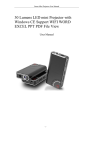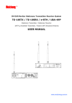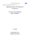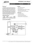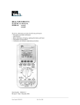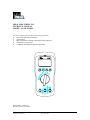
1
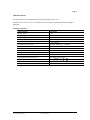
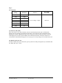
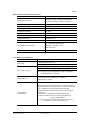
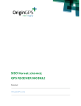
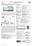
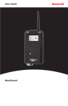
IDEAL INDUSTRIES, INC.
TECHNICAL MANUAL
MODEL: 61-354 (TRMS)
The Service Information provides the following information:
●
Precautions and safety information
●
Specifications
●
Basic maintenance (cleaning, replacing the battery and fuses)
●
Performance test procedures
●
Calibration and calibration adjustment procedures
Form number: TM61354
Revision: 2. Date: July 2006
Form number TM61354
Rev 2 July 2006
TABLE OF CONTENTS
Title
Page
Introduction
Precautions and Safety Information
1
1
Symbols
1
Safety
2
Specifications
3
General Specification
3
Measurement Characteristics
4
Voltage Specification
4
Current Specifications
4
Resistance, Diode, Frequency Specifications
5
Capacitance Specification
6
Auto Power Off, Display Auto Power Off
6
Disable Auto Power Off
6
Physical and environment characteristics
7
Certification and compliance
7
Required Equipment
8
Basic Maintenance
9
Opening the Meter Case
9
Replacing the Battery
9
Testing Fuses
10
Fuses Replacement
10
Replacing Fuses
10
Cleaning
10
Performance Tests
11
Testing the Display
11
Testing the Voltage Function
12
Testing the Resistance Function
13
Testing the Capacitance Function
13
Checking the Diode Test Function
13
Testing the AC Current Function
14
Testing the DC Current Function
14
Testing Frequency Function
14
Calibration
15
Calibrating DCV, ACV, DCA Functions
15
Calibration Adjustment Points
16
Form number TM61354
Rev 2 July 2006
Page 1
Introduction
Warning
To avoid shock or injury, do not perform the verification tests or calibration
procedures described in the manual unless you are qualified to do so.
The information provided in this document is for the use
of qualified personnel only.
Caution
The 61-350 serials contain parts that can be damaged by static discharge.
Follow the standard practices for handling static sensitive devices.
For additional information about IDEAL INDUSTRIES, INC. and its products,
and services, visit IDEAL INDUSTRIES, INC. web site at:
www.idealindustries.com
Precautions and Safety Information
Use the Meter only as described in the Service Manual. If you do not do so, the protection provided
by the Meter may be impaired. Read the “Safety Information” page before servicing this product.
In this manual, a Warning identifies conditions and actions that pose hazard (s) to the user; a
Caution identifies conditions and actions that may damage the Meter or the test instruments.
The Symbols
The symbols used on the Meter and in this manual are explained in Table A.
Table A. The Symbols
Risk of electric shock
See instruction card for details
DC measurement
Equipment protected by double or reinforced
insulation
Battery
Earth
AC measurement
Conforms to EU directives
Form number TM61354
Rev 2 July 2006
Page 2
SAFETY
Review the following safety precautions to avoid injury and prevent damage to this product or any
products connected to it. To avoid potential hazards, use the product only as specified.
CAUTION
These statements identify conditions or practices that could result in damage to the equipment or other
property.
WARNING
These statements identify conditions or practices that could result in personal injury or loss of life.
Specific precautions
Use proper Fuse. To avoid fire hazard, use only the fuse type and rating specified for this product.
Do not operate without covers. To avoid personal injury, do not apply any voltage or current to the
product without covers in place.
Electric overload. Never apply a voltage to a connector on the product that is outside the range
specified for that connector.
Avoid electric shock. To avoid injury or loss of life, do not connect or disconnect probes or test leads
while they are connected to a voltage source.
Do not operate in wet/damp conditions. To avoid electric shock, do not operate this product in wet or
damp conditions.
Form number TM61354
Rev 2 July 2006
Page 3
SPECIFICATIONS
All specifications are warranted unless noted typical and apply to the 61-354.
Stated accuracies are at 23°C±5°C at less than 80% relative humidity and without the battery indicator
displayed.
General specifications
Characteristics
Display count
Numeric update rate
Polarity display
Overrange display
Low voltage indicator
Automatic power-off time
Power source
Maximum input voltage
Maximum floating voltage
Maximum input current
Maximum open circuit Voltage (current inputs)
Overload protection A connector
V connector
Temperature Coefficient
Battery Life
Form number TM61354
Rev 2 July 2006
Description
3 1/2
1.5 times / sec
Automatic
“OL” is display
is indicated
Automatic backslit off = 10 minutes
1.5V×2 batteries
600V CAT III between V and COM
600V CAT III between any terminal and earth ground
10A between A and COM
600V between A and COM
10A (500V) fast blow fuse.
V
,V
, Ω, ,
, , Hz
0.2×(Spec. Accuracy) / °C, <18°C or >28°C
Alkaline 1.5V×2 AAA size 220 hours
Page 4
Measurement Characteristics
Accuracy is ±(% reading + number of digits) at 23°C ± 5°C, less than 80% R.H.
(1) DC Volts
Range
Resolution
200mV
100µV
2V
1mV
20V
10mV
200V
100mV
Accuracy
Over voltage
protection
±(0.5% reading + 2 digits)
DC 1000V
1000V
1V
Input Impedance: 10MΩ (over 1000MΩ in 200mV range).
(2) AC Volts
Range
Resolution
Accuracy
200mV
0.1mV
Unspecified
2V
1mV
20V
10mV
200V
100mV
±(1.5% reading + 5 digits)
Over voltage protection
750V rms
750V
1V
Input Impedance: 10MΩ // less than 100pF.
Frequency Response: 50Hz~500Hz
AC Conversion Type: AC conversions are ac-coupled true rms responding, calibrated to the rms value
sine wave input.
Crest Factor: C.F. = Peak/RMS
+1.5% addition error for C.F. from 1.4 to 3.
+3.0% addition error for C.F. from 3 to 4.
(3) DC Current
Range
2A
Resolution
1mA
10A
10mA
Overload Protection: A input: 10A (500V)
(4) AC Current
Range
2A
Resolution
Accuracy
Voltage Burden
±(1.0% reading + 2 digits)
2V max
Accuracy
Voltage Burden
1mA
±(1.5% reading + 5 digits)*1
2V max
10A
10mA
Frequency Response: 50Hz~500Hz
Overload Protection: A input: 10A (500V)
*1 AC Conversion Type: Conversions type and additional specification are same as AC Voltage.
Form number TM61354
Rev 2 July 2006
Page 5
(5) Resistance
Range
Resolution
200Ω
0.1Ω
2KΩ
1Ω
20KΩ
10Ω
200KΩ
100Ω
2MΩ
1KΩ
20MΩ*
10KΩ
Open circuit Voltage: -1.3V approx.
* <100 dgt of reading rolling.
Over voltage
protection
Accuracy
±(0.7% reading + 3 digits)
600V rms
±(1.0% reading + 3 digits)
±(1.5% reading + 3 digits)
(6) Diode Check and Continuity
Range
Resolution
Accuracy
Max. Test
Current
Max. Open
Circuit Voltage
10mV
±(1.5% reading + 5 digits)*
1.5mA
2V
* For 0.4V ~ 0.8V
Overload Protection: 600V rms max.
Continuity: Built-in buzzer sounds when measured resistance is less than 270Ω and sound off when
measured resistance is more than >850Ω.
Between 270Ω to 850Ω the buzzer maybe sound or off either.
(7) Frequency
Range
Resolution
2000Hz
1Hz
20KHz
10Hz
200KHz
100Hz
2MHz
1KHz
Sensitivity **
Accuracy
Overload
protection
Frequency:
0.01% ± 2 digit
600V rms
100mV rms *
250mV rms
20MHz
10KHz
1V rms
* Less than 20Hz the sensitivity is 1.5V rms.
** Max. Sensitivity: <5 Vac rms
Form number TM61354
Rev 2 July 2006
Page 6
(8) Capacitance
Range
Resolution
2nF
1pF
20nF
10pF
200nF
100pF
2μF
1nF
20μF
10nF
200μF
100nF
2mF*
* <100 dgt of reading rolling.
Accuracy
Over voltage
Protection
±(1.9% reading + 8 digits)
600V rms
1μF
(9) Auto Power Off (APO)
If the meter idles for more than 10 minutes, the meter automatically turns the power off. When this
happens, the state (non-logic measurement) of the meter is saved, the meter can be turned back on by
pressing any switch or changing the rotary switch. If the meter is Re-Powered by pressing a switch, the
LCD display the saved state, press the Hold switch to disable the hold state. The meter will alarm 15
seconds before automatically turning power off, any key press or rotary change will reset Auto-Power-Off.
(10) Disable Auto Power Off
In order to disable auto power off function, power up the meter while pressing down any switch other than
the “Hold” and “NCV” switch.
Form number TM61354
Rev 2 July 2006
Page 7
Physical and Environmental Characteristics
Characteristics
Description
Dimensions (H×W×D)
2.9 Inch×6.14 Inch×1.34 Inch (without holster)
3.15 Inch×6.45 Inch×1.73 Inch (with holster)
Weight (with battery)
0.25Kg
With holster
0.35Kg
Environmental characteristics
Temperature operating
0 to +50°C
Non-Operating
-20 to +60°C
Humidity (operating)
<80% R.H.
Altitude Operating
2,000M (6560 ft.)
Non-Operating
12,300M (40354 ft.)
Vibration & shock Operating
MIL-T-28800E TYPE II Class 5
2.66gRMS, 5 to 500Hz, 3axes
(10 minutes each)
Indoor Use
Indoor Use
Certifications and compliances
Safety
Input rating
Over voltage category
Description
Designed to ICE 1010-1, UL3111-1 and CSA specifications
V / Ω: Category III 600 Volts
V / Ω: Category II 1000 Volts
CAT III: Distribution level mains, fixed installation.
CAT II: Local level mains, appliances, portable equipment
CAT I: Signal level, special equipment or parts of equipment,
telecommunication, electronics.
Pollution Degree 2
Do not operate in environments where conductive
Pollutants may be present.
EC Declaration
of Conformity
Meets the intent of Directive 89/336/EEC for Electromagnetic
Compatibility and Low Voltage Directive 73/23/EEC for product
safety. Compliance was demonstrated to the following
specifications as listed in the official Journal of the European
Communities:
En 55011 Class A: Radiated and Conducted Emissions.
En 50082-1 Immunity: IEC 801-2 Electrostatic Discharge
IEC 801-3 RF Radiated
En 61010-1 Safety requirements for electrical equipment for
measurement, control, and laboratory use.
Form number TM61354
Rev 2 July 2006
Page 8
Required Equipment
Required equipment is listed in Table B. If the recommended models are not available, equipment with
equivalent specifications may be used.
Repairs or servicing should be performed only by qualified personnel.
Table B. Required Equipment
Equipment
Calibrator
Required Characteristics
AC Voltage Range: 0 ~ 750V AC
Accuracy: ±0.07% (Basic)
Frequency Range: 40 ~ 1KHz
Accuracy: ±2%
DC Voltage Range: 0 ~ 1000V DC
Accuracy: ±0.006% (Basic)
Current Range: 0 ~ 10A
Accuracy: AC (40Hz to 1KHz): ±0.08% (Basic)
DC: ±0.02% (Basic)
Frequency Source: 5.00Hz ~ 100MHz
Accuracy: ±0.001%
Amplitude: 0.5V p-p ~ 1.0V p-p (square wave)
Accuracy: ±5%
Resistance Range: 1Ω ~ 100MΩ
Accuracy: ±0.03% (Basic)
Capacitance Range: 1pF ~ 10mF
Accuracy: ±0.10% (Basic)
Form number TM61354
Rev 2 July 2006
Recommended Model
Fluke 5500 or Wavetek
9100 Calibrator or
equipment
Page 9
Basic Maintenance
Warning
To avoid shock, remove the test leads and any input signals before opening the case or replacing the
battery or fuses.
Opening the Meter Case
Caution
To avoid unintentional shock, always place the uncovered Meter assembly on a protective surface.
When the case of the Meter is open, circuit connections are exposed.
To open the Meter case, refer Figure 1 and do the following:
1. Disconnect test leads from any live source, turn the rotary switch to OFF, and remove the test leads
from front terminals.
2. Remove the battery door by using a Phillips-head screwdriver to turn the battery door screws turn
counter-clockwise.
3. The case bottom is secured to the case top by four screws. Using a Phillips-head screwdriver,
remove the four screws.
Replacing the Battery
The Meter is powered by 1.5V x 2 batteries.
Figure 1
Form number TM61354
Rev 2 July 2006
Page 10
Testing Fuses
To test the internal fuses of the meter.
1. Turn the rotary selector switch to the Ω position.
2. To test FS1, plug a test lead into VΩHz input terminal, and touch the probe to the A input terminal. The
display should indicate between 0.0 to 0.2Ω. FS1 (10A 500V) (Bussmann BBS-1 recommended). If display
reads higher than 0.2Ω, replace the fuse.
Fuse Replacement
Refer to the following figure to replace fuse:
Use only a fuse with the amperage, interrupt, voltage, and speed rating specified.
Fuse rating: 10A, 500V, Fast
Replacing Fuses
Warning
To avoid electrical shock, remove the test leads and any input signals before replacing the battery or fuses.
To prevent damage or injury, INSTALL ONLY quick acting fuses with the following Amp/Volt current
interrupt rating:
FS1 Fuse: 10A, 500V, FAST. Minimum interrupt rating 10,000A
Cleaning
Warning
To avoid electrical shock or damage to the Meter, never allow water inside the case. To avoid damaging the
Meter’s housing, never apply solvents to the Meter.
Form number TM61354
Rev 2 July 2006
Page 11
Performance Tests
The following performance tests verify the complete operability of the Meter and check the accuracy of
each Meter function against the Meter’s specifications.
Accuracy specifications are valid for a period of one year after calibration, when measured at an operating
temperature of 18°C to 28°C and a maximum of 80% relative humidity.
To perform the following tests, it is not necessary to open the case, no Adjustments are necessary, merely
make the required connections, apply the designated inputs, determine if the reading on the Meter display
falls within the acceptable range indicated.
If the Meter fails any of these tests, it needs calibration adjustment or repair.
Testing the Display
Press “HOLD” key while turning the Meter on from the “OFF” position to hold the display in the Display
Test Mode. Compare the display with the example in Figure 2. Turn off the meter to escape the test mode.
LCD Graphics 61-354
Figure 2 Display Test
Form number TM61354
Rev 2 July 2006
Page 12
Testing the Voltage Function
To verify accuracy in the AC and DC voltage ranges, do the following:
1. Turn the rotary switch to “V
” position.
2. Connect the Calibrator to the VΩHz and COM inputs on the Meter.
3. Set the Calibrator for the voltage and frequency from step 1 to 8 in Table 1.
4. Compare the reading on the Meter display with the display reading shown in Table 1.
5. If the display reading falls outside of the range shown in Table 1, the Meter does not meet specification.
Table 1 AC Voltage Test:
Step
1
Input
1.500V
Frequency
50Hz
Reading
1.472V to 1.528V
2
1.500V
300Hz
1.472V to 1.528V
3
15.00V
50Hz
14.72V to 15.28V
4
15.00V
500Hz
14.72V to 15.28V
5
150.0V
50Hz
147.2V to 152.8V
6
150.0V
500Hz
147.2V to 152.8V
7
750V
50Hz
734V to 766V
8
750V
500Hz
734V to 766V
6. Turn the rotary switch to “V
” position.
7. Set the calibration for the voltage from step 1 to 6 in Table 2.
8. Compare the reading on the Meter display with the display reading shown in Table 2.
9. If the display reading falls outside of the range shown in Table 2, the meter does not meet specification.
Table 2 DC Voltage Test:
Step
1
Input
150.0mV
Reading
149.0V to 151.0V
2
-150.0mV
-149.0V to -151.0V
3
1.500V
1.490V to 1.510V
4
15.00V
14.90V to15.10V
5
150.0V
149.0V to 151.0V
6
990V
983V to 997V
Testing the Resistance Function
To verify the accuracy of the resistance function, do the following:
1. Connect the Calibrator to VΩHz and COM on the Meter.
2. Turn the rotary switch to Ω.
3. Apply the inputs for step 1-6 in Table 3.
4. Compare the Meter display readings to the display readings in Table 3.
5. If the display reading falls outside of the range shown in Table 3, the Meter does not meet specification.
Form number TM61354
Rev 2 July 2006
Page 13
Table 3 Ω Resistance Test:
Step
1
Source
150.0Ω
Reading
148.6Ω to 151.4Ω
2
1.500KΩ
1.486KΩ to 1.514KΩ
3
15.00KΩ
14.86KΩ to 15.14KΩ
4
150.0KΩ
148.6KΩ to 151.4KΩ
5
1.500MΩ
1.482MΩ to 1.518MΩ
6
15.00MΩ
14.74MΩ to 15.26MΩ
Lead resistance on the 200Ω range is not included in error.
Testing the Capacitance Function
The Meter measures capacitance by charging the capacitor with a known direct current, measuring the
resultant voltage, and calculating the capacitance. If the same capacitance is measured on an impedance
bridge, a different reading may result. This variance is likely to be greater at higher frequencies.
To verify the accuracy of the capacitance measuring function, do the following:
1. Apply the Capacitor to the VΩHz and COM inputs on the Meter. For steps 1 through 7 in Table 4.
2. Turn the rotary switch to .
3. Compare the reading on the Meter display to the reading in Table 4.
Note: The meter selects the proper range automatically. Each measurement takes about one second per
range, 2mF takes about 4.5 seconds.
4. If the display reading falls outside of the range shown in Table 4, the Meter does not meet specification.
Table 4 Capacitance Test:
Step
1
Source
1.500nF
Reading
1.463nF to 1.537nF
2
15.00nF
14.63nF to 15.37nF
3
150.0nF
146.3nF to 153.7nF
4
1.500µF
1.463µF to 1.537µF
5
15.00µF
14.63µF to 15.37µF
6
150.0µF
146.3µF to 153.7µF
7
1.500mF
1.463mF to 1.537mF
Checking the Diode Test Function
To check the diode test function, do the following:
1. Connect the Calibrator to the VΩHz and COM inputs on the Meter.
2. Turn the rotary switch to
.
3. Apply .5V DC.
The meter display should read approx. .5V dc.
4. Built-in buzzer sounds when measured resistance is less than 270Ω and sound off when measured
resistance is more than >850Ω
Between 270Ω to 850Ω the buzzer maybe sound or off either.
Form number TM61354
Rev 2 July 2006
Page 14
Testing the amp (A) Function
To verify the accuracy of AC current measurement functions, do the following:
1.Connect the Calibrator to the A and COM inputs on the Meter.
2. Turn the rotary switch to A
.
3. Apply the inputs for steps 1-4 in Table 5.
4. For each input, compare the reading on the Meter display to the reading for your Meter in Table 5.
5. If the display reading falls outside of the range shown in Table 5, the meter does not meet specification.
Table 5 AC Current Test:
Step
1
Source
1.500A
Frequency
50Hz
Reading
1.472A to 1.528A
2
1.500A
500Hz
1.472A to 1.528A
3
10.00A
50Hz
9.80A to 10.20A
4
10.00A
500Hz
9.80A to 10.20A
.
6. Turn the rotary switch to A
7. Set the calibration for the current from step 1 - 2 in Table 6.
8. For each input, compare the reading on the Meter display to the reading in Table 6.
9. If the display reading falls outside of the range shown in Table 6, the meter does not meet specification.
Table 6 DC Current Test:
Step
1
2
Source
1.500A
Reading
1.483A to 1.517A
10.00A
9.88A to 10.12A
Testing the Frequency Function
To verify the accuracy of the Meter’s frequency function, do the following:
1. Connect the Calibrator to the VΩHz and COM inputs on the Meter.
Note: The accuracy of the Calibrator’s frequency function must be appropriate for the specified accuracy of
the Meter.
2. Set the rotary switch to Hz.
3. Set the Calibrator for the sine wave voltage and frequency for steps 1-5 of Table 8.
4. Compare the reading on the Meter display with the display reading shown in Table 8.
5. If the display reading falls outside of the range shown in Table 8, the Meter does not meet specification.
Table 8 Frequency Test:
Step
1
Soure
1500Hz
Level
100mV rms
Reading
1498Hz to 1502Hz
2
15.00KHz
100mV rms
14.98KHz to 15.02KHz
3
150.0KHz
100mV rms
149.8KHz to 150.2KHz
4
1.500MHz
250mV rms
1.498MHz to 1.502MHz
15.00MHz
1V rms
14.98MHz to 15.02MHz
5
* Max. level: <5 Vac rms
Form number TM61354
Rev 2 July 2006
Page 15
Calibration Procedure
Recalibrate your meter:
It is recommended that the multimeter be calibrated once each year.
1. Perform calibration at an ambient temperature of 23°C±2°C and a relative humidity of 75% or less.
2. Disconnect the test leads and turn the meter off. Remove the test leads from the front terminals.
3. Position the meter face down. Remove the four screws from the case bottom.
4. Remove case bottom.
(A) DCV Calibration (Adjust VR2)
5. Set the circuit board rotary switch "arrow" to the " V
" position of circuit board.
6. Set the output of DC calibrator for 150.0V±0.02% and connect to VΩHz and COM input terminals on
meter.
7. Using a small flat-tipped screwdriver adjust the potentiometer VR2 until the display reads 149.9 to
150.1.
8. Disconnect the DC calibrator from the meter.
(B) ACV Calibration (Adjust VR1, VR4)
9. Set the circuit board rotary switch "arrow" to the " V
" position of circuit board.
10. Using a small flat-tipped screwdriver adjust potentiometer VR4 until the display reads 0.000 to 0.003.
11. Set the output of AC calibration for 150.0V 100Hz and connect to VΩHz and COM input terminals on
meter.
12. Using a small flat-tipped screwdriver adjust the potentiometer VR1 until the display reads 149.9 to
150.1.
13. Disconnect the AC calibrator from the meter.
(C) DCA Calibration (Adjust VR66, VR67, VR68)
14. Set the circuit board rotary switch “arrow” to the
A position circuit board.
15. Using a small flat-tipped screwdriver adjust potentiometer VR67 until display reads +0.001 to -0.001.
16. Set the output of DCA calibrator for 1.5A and connect to A and COM input terminals on meter.
17. Using a small flat-tipped screwdriver adjust potentiometer VR66 until the display reads 1.499 to 1.501.
18. Repeat 15~17.
19. Set the output of DCA calibrator for 10.0A and input terminals on meter.
20. Using a small flat-tipped screwdriver adjust potentiometer VR68 until the display reads 9.99A to
10.00A.
21. Disconnect the DCA calibrator from the meter.
Form number TM61354
Rev 2 July 2006
Page 16
VR1
VR67
VR2
VR68
VR66
Figure 5 61-354 Calibration Adjustment Points
Form number TM61354
Rev 2 July 2006
Page 17
Form number TM61354
Rev 2 July 2006