1
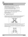
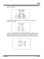
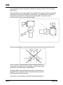
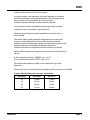
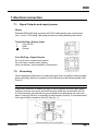
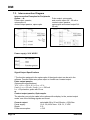
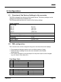
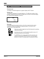
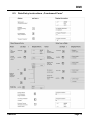
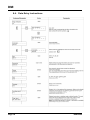
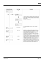
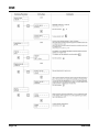
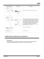
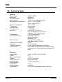
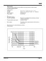
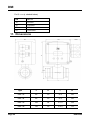
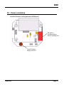
Operating instruction
for
Electromagnetic Flowmeter
Model: DMI
DMI
1. Note
These instruction are to be read before unpacking and operating the device and are
to be closely heeded at all times.
The devices are only to be used, maintained and serviced by persons familiar with
these operating instructions and with the prevailing regulation applying to procedural
safety and the prevention of accidents.
2. Contents
1. Note ........................................................................................................ 2
2. Contents................................................................................................. 2
3. Specific Application.............................................................................. 3
4. Operating Principles............................................................................. 3
5. Instrument Inspection ............................................................................ 3
6. Mechanical connection......................................................................... 4
6.1.Installation and start-up ......................................................................... 4
7. Electical connection.............................................................................. 9
7.1.Signal Outputs and supply power........................................................ 9
7.2.Grounding .............................................................................................. 9
7.3.Interconnection Diagram ....................................................................10
8. Configuration.......................................................................................11
8.1.Overview of the Factory Settings in the converter ...........................11
8.2.DMI configuration................................................................................11
8.3.Data Entry instructions „Condensed Form“......................................13
8.4.Data Entry Instructions ........................................................................14
9. Mechanical putting into operation .....................................................17
10. Technical data .....................................................................................18
11. Dimensions..........................................................................................20
12. Fuse Locations....................................................................................21
13. Declaration of conformance...............................................................22
Manufactured and sold by:
Kobold Messring GmbH
Nordring 22-24
D-65719 Hofheim
Tel.: +49(0)6192-2990
Fax: +49(0)6192-23398
E-Mail: [email protected]
Internet: www.kobold.com
Page 2
DMI 09/00
DMI
3. Specific Application
The DMI is to be installed only in the specified applications. Every usage which
exceeds the specifications is considered to be non-specified. Any damages
resulting thereform are not the responsibility of the manufacturer. The user assumes
all risk for such usage. The application specifications include the installation, start-up
and service requirements specified by the manufacturer.
4. Operating Principles
The flowrates of liquids with a conductivity of at least 50 µS/cm
can be measured with this flowmeter (Miniflow).
Faraday's Laws of Induction state that a voltage is generated
which is proportional to the average flow velocity. This signal
voltage is measured at two electrodes which are in contact with
the fluid.
Various signals are available at the outputs of the converter for
further processing (e.g. flowrate proportional pulses, 20 mA
current output, min./max. contact output for process monitor-ing).
The electrical connections are made with a plug.
5. Instrument Inspection
These devices are checked before despatch and sent away in perfect condition.
Should the damage to a device be visible, we recommend a thorough inspection of
the delivery packing. In case of damage, please inform your parcel service/
forwarding agent immediately, since they are responsible for damages during
transit.
Scope of delivery:
• Magnetic Inductive Flowmeter
• Service manual
DMI 09/00
Page 3
DMI
6. Mechanical connection
The DMI incorporates a threaded process connection. The
diameter difference of the transition from the pipeline to the
flowmeter should be kept to a minimum.
For this reason additional threaded adapters, are mounted on
the flowmeter and shipped together (exceptions: flowmeter size
3/8" / DN10 and flowmeters with NPT threads).
These adapters provide the ability to install the flowmeter using
a coupling union either in plastic pipelines (using the threaded
adapter) or to install it in copper or other metal pipelines (by re-moving
the threaded adapter and connecting directly to the
threads on the flowmeter).
See the following Table for an overview.
6.1.
Installation and start-up
The DMI should not be installed in the vicinity of strong electromagnetic fields. The
installation orientation is arbitrary! It is essential that the flowmeter always be
completely filled with fluid. Partial filling results in measurement errors.
The DMI measures in both flow directions. The forward flow direction is shown by the
arrow on the meter primary. If DMI should measure only in one flow direction, a
straight pipe section of 3 x DN upstream and 2 x DN downstream is required. If DMI
should measure in both flow directions, 3 x DN straight pipe section upstream and
downstream is required.
Page 4
DMI 09/00
DMI
Valves or other shutoff devices should be installed downstream form the flowmeter
so that it connot drain.
A slight slope in the pipeline of approx. 3 % is advantageous in eliminating gas
pockets in the flowmeter.
Installations in vertical pipelines are ideal when the fluid flows up. Installation in drop
lines, i.e. the fluid flows from the top to the bottom should be avoided because it is
impossible to assure the flowmeter will remain full due to an equilibrium condition
which may exist between the downward flowing fluid and gas being forced upward.
DMI 09/00
Page 5
DMI
In general the flowmeter should be installed in the pipeline with the PG-Connectors
facing down.
When installed in a horizontal pipeline the imaginary line between the two electrodes
should be horizontal if at all possible to prevent air or gas bubbles from interfering
with the flow signal which is measured at the electrodes. The position of the
electrode axis is shown in the adjacent figures.
Entrained gas bubbles carried along with the fluid cause flow measurement errors.
When installed in free discharge lines the flowmeter should not
be located in the high point in the pipeline or at the outlet end of
the pipeline (flowmeter drains, gas bubbles).
Standing eddies (after partially open valves or when there are
tangential inflows upstream of the flowmeter) which persist into
the flowmeter should be avoided.
If a pump is used to produce the flow the flowmeter should be
Page 6
DMI 09/00
DMI
installed on the pressure side of the pump.
In mixing systems, the flowmeter should be installed in a location
where the complete mixing has taken place. Non-homoge-neous
fluid conditions in the flowmeter are to be avoided.
Pulsation dampers should be utilized where required.
The ground connection between the two plugs on the converter
housing is to be connected to a good ground.
There are grounding electrodes integrated in the meter tube in
the flowmeter.
The meter tube and the electrodes integrated in the meter tube
come in contact with the fluid. Check before start-up that the
materials used are chemically resistant to the fluid being measured.
Gaskets should be used when installing the flowmeter.
These should also be compatible with the fluid being metered.
Assure that the maximum temperature will not exceed the fol-lowing
values:
a) For meter tubes made of PEEK max. 110 °C
b) For meter tubes made of PETP max. 60 °C
The meter tube material is listed on the Instrument Tag on the
flowmeter.
Observe the max. torque values when tightening the connectors on the DMI
Torque Specifications for process connection
DN [mm]
on PEEK
on PETP
10
20 Nm
13 Nm
15
21 Nm
14 Nm
25
25 Nm
16 Nm
50
51 Nm
34 Nm
Avoid usage of ferromagnetic process connectors.
DMI 09/00
Page 7
DMI
Information for using the threaded Adapters
a) Flowmeter is installed in a plastic pipeline.
DN
Suitable for plastic
Threaded Connection at Miniflow for
pipelines with ∅-outside
Plastic Pipelines
10
16 mm
G 3/4 (no threaded adapter)
15
20 mm
G 1 (with threaded adapter G¾-G1)
25
32 mm
G1½ (with threaded adapter G1¼-G1½)
50
63 mm
G2¾ (with threaded adapter G2½-G2¾)
Example:
The DMI is to be installed in a plastic pipeline with a 20 mm outside diameter.
The above table indicates that a 1/2“ / DN 15 meter size is required. The adapter
shipped with the flowmeter must be used. This increased the G ¾“ thread on the
flowmeter to G 1“ so that the coupling union, which has a G 1“ thread size for size
plastic pipeline, can be connected to the flowmeter.
b) Flowmeter is installed in a metal (e.g. copper) pipeline
DN
Suitable for plastic
Threaded Connection at DMI for Metal
pipelines with ∅-outside
pipeline
10
14 mm = ½" tubing
G 3/4 (no threaded adapter)
15
18 mm = ¾" tubing
G 3/4 (no threaded adapter)
25
28 mm = 1" tubing
G1¼ (no threaded adapter)
50
54 mm = 2" tubing
G2½ (no threaded adapter)
Example:
The DMI is to be installed in a metal pipeline with a 14 mm outside diameter, i.e. ½“
metal tubing.
The above table indicates that a 3/8“ / DN 10 meter size is required. The adapter
shipped with the flowmeter must be removed since it is only required for installations
in plastic pipelines. With the threaded adapter removed the 3/8“ / DN 10 flowmeter
size has a G ¾“ threaded connection. This is the connection size required for the G
¾“ coupling union used with the ½“ metal tubing.
Page 8
DMI 09/00
DMI
7. Electical connection
7.1. Signal Outputs and supply power
Wiring
Standard DIN 43650 plug connector with PG 9-cable glands, pipe cross section
max. 1,5mm², IP 65 rating. Open plug and wire according following instructions:
Three-PIN-Plug = Supply power
1
24 V AC/DC
2
GND
Ground
Four-PIN-Plug = Signal Outputs
Pin 1+2 20 mA or contact input (option)
Pin 3+4 Pulse / contact output (option)
(Also see Section „Interconnections, Peripherals“)
7.2. Grounding
When installing the flowmeter in a metal to the plug (Point A) together with the supply
power (left plug), then the connection at Point B must be at the same potential as at
Point A.
Attention
If a ground connection is made to the plug (Point A) together with the supply power
(left plug), then the connection at Point B must be at the same potential as at Point
A. If this cannot be assured then the ground should be connected at only one point –
either in the plug (Point A) or externally to the flowmeter (Point B). If is recommended
that a ground be connected to Point B. (See fig. 11)
DMI 09/00
Page 9
DMI
7.3. Interconnection Diagram
Interconnection Examples for Peripherals
Option: ...A..
Pulse output, passive,
optocoupler or
contact output passive, optocoupler
Pulse output, optocoupler
and current output 0/4 – 20 mA or
contact output, passive,
optocoupler and current output 0/420 mA)
Option: ...B..
Power supply: 24 V AC/DC
Signal Output Specifications
* The function assigned to the optocoupler of the signal output can be set in the
software. Function either as a pulse output or function as a contact output.
Pulse output passive
(Optocoupler specifications:)
16 V ≤ U CEH ≤ 30 V; 0 V ≤ U CEL ≤ 2 V;
0 mA ≤ I CEH ≤ 0,2 mA ; 2 mA ≤ I CEL ≤ 220 mA
fmax = 20 pulse/sec; pulse with 20 ms
or
Contact output passive, Optocoupler
The selection can only be made in the options with a display. In the „contact output
mode“ one of the following signals can be set:
Current output:
Power supply:
Ripple:
Power consumption:
Page 10
selectable 0/4 to 20 mA; Burdon ≤ 600 Ohm
16,8...26,4 VAC bzw. 16,8...31, 2 VDC
5%
<5W
DMI 09/00
DMI
8. Configuration
8.1. Overview of the Factory Settings in the converter
The DMI is shipped form the factory with preset values. The factory settings can be
changed at the flowmeter installation site.
The following table provides an overview of the factory settings:
Factory settings
Flow range
DN 10
DN 15
DN 25
DN 50
Units
50 l/min
100 l/min
300 l/min
1200 l/min
l/min
Current output (Option)
4 - 20 mA
Damping
5 Sec.
Pulse output
1 pulse / Liter
Pulse width
20 ms
8.2. DMI configuration
The converter can now be configured using menu structured clear text displays.
• Flow range and damping can be set in an infinite number of steps.
• Additional direct reading units can be user selected for the flowrate
measurements.
• The function assigned to the optocoupler for the pulse output can be changed.
(e.g. min. alarm, max. alarm etc.)
Flow Range Table
DN
10
15
25
50
Flow Range in l/min can be set anywhere between
min. 0 - 2,5 l/min
max. 0 - 50 l/min
min. 0 - 5 l/min
max. 0 - 100 l/min
min. 0 - 15 l/min
max. 0 - 300 l/min
min. 0 - 60 l/min
max. 0 - 1200 l/min
DN
10
15
25
Flow Range in Usgal/min can be set anywhere between
min. 0 - 1,0 gal/min
max. 0 - 10 gal/min
min. 0 - 1,5 gal/min
max. 0 - 25 gal/min
min. 0 - 4 gal/min
max. 0 - 80 gal/min
DMI 09/00
Page 11
DMI
50
min. 0 - 16 gal/min
max. 0 - 320 gal/min
Display format
The display of the DMI magmeter is a graphic display with 97*32 pixel.
Display view
The flowrate is displayed in the upper display line. The difference totalizer, which
indicates forward and reverse flow as a single value, is shown in the lower display
line. Alarms will be displayed in clear text.
>V
122.5
l/min
>V
3256 l
Data entry
During data entry the converter remains on-line, the current and pulse outputs
continue to indicate the instantaneous operating values. The function of the
individual keys is described below:
#
Clear key is used to toggle back and forth between the operating
mode and the menus.
Arrow keys are used to scroll forward throught the menus. All
desired parameters can be accessed.
The ENTER function requires that both of the arrow keys, be
pressed simultaneously. ENTER is used to turn the program
protection on and off to change and fix new parameter values.
Page 12
DMI 09/00
DMI
8.3. Data Entry instructions „Condensed Form“
DMI 09/00
Page 13
DMI
8.4. Data Entry Instructions
Page 14
DMI 09/00
DMI
DMI 09/00
Page 15
DMI
Page 16
DMI 09/00
DMI
9. Mechanical putting into operation
Gas pockets
It has to be accertained that the instrument is always completely filled with fluid.
Partial fitting as well as gas pockets results in measurement errors.
DMI 09/00
Page 17
DMI
10. Technical data
Materials
Body / lining:
Electrodes:
Ground electrode:
Max. pressure:
Max operating Temperature.:
Ambient Temperature:
Conductivity:
Inlet and outlet:
(recommended)
Accuracy:
Repeatability:
Creep suppression:
Response time:
Frequency of excitaion:
Protection:
Vibration resistance:
Pressure loss:
Electronic
Power supply:
Ripple:
Power consumption:
Display:
Electr. connection:
Impulsausgang:
fest eingestellt
Pulse width:
Pulse frequency:
Output signal:
Page 18
PEEK or PETP
Hastelloy C
Hastelloy C
10 bar (over whole temp. range)
-25°C...+110°C (PEEK)
-25°C...+60°C (PETP)
-25°C...+50°C
min. 50 µS/cm
3 x DN inlet
2 x DN outlet
± 3% (für Q > 0,07 x Q max )
±Q max x 0,0021 (für Q ≤ 0,07 x Q max )
(Option: ± 1,5% of actual range)
≤ 0,2% of actual range
adjustable 0-10 % of
the adjusted range
(Hysterisis 1%)
5s (step function 0-99%)
Adjustable between 5-40 Sec.
6¼ Hz
IP 65, EN 60529
15 m/s2 (max. axeleration at 10-150 Hz)
Series DMI don´t have any parts loading into the
measuring tube. The pressure loss disregardingly
small.
16,8-31,2 VDC or 16,8-26,4 VAC
5%
<5W
3 line (97 x 32 pixel)
plug in DIN 43650
1 pulse / Liter (Gallon)
20 ms
max.20 Hz
0 or 4-20 mA (adjustable); Load ≤ 600 Ohm
DMI 09/00
DMI
Optocoupler
The opotcoupler output can be set either as a pulse output or switch output.
a) Pulse output passive
(Optocoupler:)
Voltage:
16 V ≤ U CEH ≤ 30 V; 0 V ≤ U CEL ≤ 2 V;
Current:
0 mA ≤ I CEH ≤ 0,2 mA ; 2 mA ≤ I CEL ≤ 220 mA
Max. frequency:
20 pulses/sec;
Pulse width:
fixed 20 ms
or
b) Switch output
Function adjustable:
Technical data optocoupler:
Error signal:
Example: forward/backflow-switching, min/max
contact, system alert
see pulse output
The switch output (optocoupler) can be set as a
system alert
Measurment error under reference condition
(Pulse output)
DMI 09/00
Page 19
DMI
For Q maxDN (s. shedule below)
DN
Qmax DN
10
50 l/min
15
100 l/min
25
300 l/min
50
1200 l/min
11. Dimensions
Page 20
Type
L
D
∅
H
DMI-..02
85
53
G¾
150
DMI-..04
85
53
G¾
150
DMI-..06
100
64
G 1¼
159
DMI-..08
130
92
G 2½
175
DMI 09/00
DMI
12. Fuse Locations
Location of fuse on the signal input PCB board
DIP switch
for range setting
20mA, damping, etc.
Fuse for Power
supply 500 mA T
DMI 09/00
Page 21
DMI
13. Declaration of conformance
We, Kobold-Messring GmbH, Hofheim-Ts., Germany, declare under our sole
responsibility that the product
Electromagnetic flowmeter
Type: DMI...
to which this declaration relates is in conformity with the standards noted below:
EN 50081-1
EN 50081-2
EN 50082-1
EN 50082-2
3/93
3/94
3/93
2/96
following the provision of European Directives:
89/336/EWG
Signed:
Datum: 10.10.00
H. Peters
Page 22
M. Wenzel
DMI 09/00