1
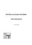
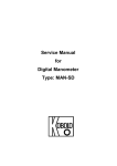
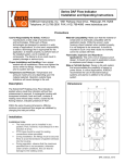
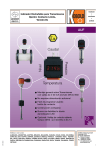
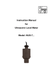
Operating Instruction
for
Calorimetric Flow Monitoring Device
Model: KAL
KAL
1. Contents
1. Contents........................................................................................................2
2. Note ..............................................................................................................3
3. Instrument Inspection....................................................................................3
4. Regulated Use ..............................................................................................4
5. Operating Principle .......................................................................................5
6. Mechanical Connection.................................................................................5
7. Electrical Connection ....................................................................................6
8. Limiting Contacts ..........................................................................................6
9. Alignment / Balancing ...................................................................................7
10. Commissioning ...........................................................................................10
11. Maintenance ...............................................................................................10
12. Fault Signalling ...........................................................................................11
13. Technical Information..................................................................................11
14. Order Codes ...............................................................................................12
15. Dimensions .................................................................................................13
16. Declaration of Conformance .......................................................................14
Manufactured and sold by:
Kobold Messring GmbH
Nordring 22-24
D-65719 Hofheim
Tel.: +49(0)6192-2990
Fax: +49(0)6192-23398
E-Mail: [email protected]
Internet: www.kobold.com
Page 2
KAL 07/04
KAL
2. Note
Please read and take note of these operating instructions before unpacking and
setting the unit for operation, and follow the instructions precisely as described
herein.
The devices are only to be used, maintained and serviced by persons familiar
with these operating instructions and with the prevailing regulation applying to
procedural safety and the prevention of accidents.
By usage in machines, the measuring unit should be used only then when the
machines fulfil the EWG-machine guide lines.
PED 97/23/EG
for KAL-11.. and KAL-12..
In acc. with Article 3 Paragraph (3), "Sound Engineering Practice", of the
PED 97/23/EC no CE mark.
Table 8, Pipe, Group 1 dangerous fluids
3. Instrument Inspection
These devices are checked before dispatch and sent away in perfect condition.
Should the damage to a device be visible, we recommend a thorough inspection
of the delivery packing. In case of damage, please inform your parcel service/
forwarding agent immediately, since they are responsible for damages during
transit.
Scope of delivery:
• probe with 2 m PVC as standard
• Electronic setting system
KAL 07/04
Page 3
KAL
4. Regulated Use
The KAL is to be installed only in the specified applications. Every usage which
exceeds the specifications is considered to be non-specified. Any damages
resulting therefrom are not the responsibility of the manufacturer. The user
assumes all risk for such usage. The application specifications include the
installation, start-up and service requirements specified by the manufacturer.
Devices from the KAL model series are used for the monitoring of liquid flow.
Limiting relay
The devices are equipped with limiting relays for monitoring the flow speed of
liquids (KAL-E1...-E3).
Trend display
An LED bar display shows the current flow value and the set switch point via a
flashing LED (only on models KAL-E2... and KAL-E3...).
Probes
Probes are available in two options: as a screw-type or in-line version.
Model KAL devices are always made up of two structural components
• Probe
• Electronic setting system
The devices may only be used for liquids to which the probe housing materials
are resistant. With proper installation and maintenance, the probes display no
sensitivity to soiling and cause practically no pressure loss.
Materials
KAL-11...
Brass material
KAL-12..., KAL-23..., KAL-53... St. steel material 1.4301
KAL-24..., KAL-54...
St. steel material 1.4571
Setting ranges in relation to nominal tube diameter
ND (mm)
8
10
15
20
25
30
Page 4
Range (l/min) water
0,12 - 6,0
0,19 - 9,4
0,42 - 21,8
0,75 - 37,7
1,18 - 59,0
1,7 - 84,8
ND (mm)
40
50
60
80
100
150
Range (l/min.) water
3,0 - 150
4,7 - 235
6,8 - 340
12,0 - 603
18,8 - 942
42,4 - 2120
KAL 07/04
KAL
Attention! For the measuring ranges gives the flow speed was
converted to the nominal tube diameter. It should be noted in line
with this that in the tube towards the wall section the flow speed
approaches 0. Depending on nominal tube diameter, screw depth of
the probe and flow profile, occasional deviations, some of them
considerable, may result.
5. Operating Principle
The all-metal design electronic flow monitor device functions according to proven
calorimetric principles. The measuring probe is heated up a few degrees from the
inside outwards in relation to the flow medium which it is penetrating. If the
medium is flowing then the heat produced in the probe is carried away by the
medium, i.e. the probe becomes cooler. This cooling represents a measuring of
the flow speed.
The electronic setting system compares the desired flow speed with the actual
speed and activates an output relay when the desired value is not reached. By
the use of a micro-controller, simple calibrations is made possible. In this way
optimum temperature compensation can be achieved.
6. Mechanical Connection
Before installation:
• Ensure that the actual flow quantity corresponds to the setting range of the
device (i.e. to the flow speed).
• Ensure that the permitted maximum operating pressure and temperatures for
the device are not being exceeded. (See point 13 Technical Information)
Installation:
Mount the sensor in the pipe (KAL-1...)- in a sleeve welded to the pipe (KAL-2...).
Fitting position:
The function of the sensor is not dependent on
their fitting position, provided that the pipe is
completely filled with flow medium. The place
where the sensor are fitted must be free from
turbulence in the medium. (4x pipe section in
front of and behind sensor). If the medium is
likely to cause any deposits in the tube, then an
appropriate
fitting
position
alongside
is
recommended.
KAL 07/04
Page 5
KAL
7. Electrical Connection
Warning! Ensure that the voltage values of your installation
correspond to the voltage values given on the device´s specification
plate.
• Make sure that the electrical power supply is off.
• Connect the sensor cable to terminals 6 & 8 on the setting system.
• Connect the power supply (voltage supply) to terminals 15 & 16.
Temperature relay only on models
KAL-E3.
The relais are illustrated in fallen state.
AC voltage supply
220 VAC, 110 VAC, 24 VAC +/- 10%, 50-60 Hz
DC voltage supply
24 VDC + 15%, - 10%
8. Limiting Contacts
Only on KAL-E1.../KAL-E2...
1x change - over relay for flow speed
Only on KAL-E3...
1x change - over relay for flow speed
1x change - over relay for temperature
Page 6
KAL 07/04
KAL
9. Alignment / Balancing
Initial operation:
9.1. Fit sensor in pipe (ensure correct fitting location, see point 6 Mechanical
Connection).
9.2. Connection sensor cables to electronic circuitry (see point 7 Electrical
Connection).
9.3. Fill pipe with flow medium.
Caution! There must be no air bubbles on the sensor. Flow speed
must be at 0.
9.4. Commission electronic circuitry (switch on supply voltage)
9.5. Only on model KAL-E-3...Set temperature potentiometer (2) to left-hand
stop.
9.6. Zero point alignment. Briefly activate the "SET"key (5) (using a suitable
object e.g. ball point pen)
9.7. "Flow" LED (6) flashes for about 30 seconds. After this time the "Flow"LED
goes off (6). The device is now operational., continue with point 9.9.
9.8. In case of malfunction the "Flow" LED flashes continuously. Press the"SET"
key once again. Device will switch back into measuring mode. Check
mechanical and electrical installation and recommence operational
procedure from point 9.4.
9.9. Switches on installation and set maximal flow.
If the flow speed is significantly less then 2 m/s, then on the trend display (3)
there will be possibly fewer then 8 LEDs on.
It is now possible to extend this display (3) to the full range (8 LEDs). This can
only be successfully achieved, however, if the flow speed is somewhere between
0,25-1,8 m/s.
• Set "Flow" potentiometer (1) (see illustration) to right-hand stop
(only on KAL-E3...; Set temperature potentiometer to left-hand stop)
• Briefly activate SET key (5)
• Flow LED (6) will flash for 30 seconds. After this time the Flow
LED will go 30 off.
KAL 07/04
Page 7
KAL
It is possible at any time to reset the electronic circuitry to the full range
• Flow potentiometer (1) at right-hand stop
• (Only on KAL E3; Temperature potentiometer (2) to left handstop)
• Press the SET key (5) and hold in position until the FLOW LED
stops
The device has now been reset into basic functioning mode.
The device is now adjusted to your medium. You can now set your switch point.
(In case of malfunction see point 9.8)
9.10. Set operational flow.
Switch point setting: Model KAL-E-1...
• The further the Flow-potentiometer (1) is turned to the left, the lower the switch
point.
• The further the Flow-potentiometer (1) is turned to the right, the higher the
switch point.
Switch point setting: Model KAL-E-2.../E-3...
• Set Flow-potentiometer (1) to left-hand stop. The first LED on the luminous
display (3) will flash. Any number of LED´s on the luminous display will be
continuously illuminated.
• Turn "Flow" potentiometer (1) to the right until the desired switch point is
reached. The current switch point will be displayed by a flashing LED.
Display 3
XXXXX
Flashing
flow speed
XXXXXX
LED display flashin
Explanation
Result
flow>switch point
Flow relay pick-up made
XXXXXX
flow>switch point LED
Flow LED illuminated
Flow relay pick-up made
XXX
flashes at double
frequency
Flow<switch point
XXXXXX
ö
Flow LED illuminated
Flow LED off
Flow relay open
Page 8
KAL 07/04
KAL
KAL 07/04
Page 9
KAL
Only KAL-E-3...
with more than 10 m cable between sensor and electronic circuitry, as well as
increased accuracy when measuring temperature.
Temperature alignment
•
•
•
•
•
•
•
•
Page 10
Caution! Disconnect from power supply.
Connect full length extention cable (>10 m) (terminals 6&8)
Connect 100 Ohm ±1% resistor (part of delivery package) in place of
sensor at the end of the instrument leads.
Set temperature potentiometer (2) at 80° C (right - hand stop).
Reconnect power supply and switch device on.
Briefly press SET key (5).
The temperature LED will flashed and switch off again after approx. 10
seconds. In case of malfunction, see point 9.8, Initial operation. If the
temperature LED flashes more quickly, this could be caused by the fact
that the probe is connected instead of a 10 Ohm resistor.
Remove the 100 Ohm resistor and replace the sensor.
KAL 07/04
KAL
10. Commissioning
The use of this meter in machines acc. to directive 89/392/EWG is prohibited
until the complete machine complies to this directive.
Illustration KAL- E3 ...
(1) Potentiometer
Setting of flow switch
Zero point alignment-turn to left-hand stop
-Extending measuring range
-turn to right-hand stop
(2) Potentiometer
Setting of temperature
switch point (only KAL E3)
(3) LED trend display for flow
speed and switch point
(6) LED-Flow is
illuminated when
flow is greater
then set switches
point.
(4) LED temp is
illuminated when
operational temp. is below
the set temp. limit value.
(5) SET- key (for alignment: extending
measuring range)
11. Maintenance
The device requires no maintenance. The sensor be checked at monthly
intervals for deposits (limescale etc.) and cleaned where necessary.
KAL 07/04
Page 11
KAL
12. Fault Signalling
When the alarm functions, the flow relay is released.
This happens in the following cases:
• Actual value < Desired value
• Short - circuit
• Line break
• Power failure
13. Technical Information
Sensor
Materials
Housing:
cable:
cable screw fittings:
cable:
Setting ranges:
Medium temperature:
max. pressure:
1.4301
PVC
Nickel - plated brass: PG 7
Length=2m, max. length 100 m
(can be extended by customer)
Number of Leads=2
Lead cross section = 0,56 mm²
AWG 20, flexible cord
4 cm/s ... 200 cm/s
-20° C to 80 °C
(Option: KAL-...HT-20...+120 °C
100 bar
Caution! KAL 1132 and 1140 max. 25 bar
Protection (EN 60529):
Electronic system
Power draw:
Breaking capacity:
Switch point alignment
Switch function:
Output:
Switch status display:
Page 12
IP 68
max. 3,6 Watts
max. 250 V, max 3 A
via potentiometer
Relay pick-up is made during flow,
(terminal 9 & 10 closed, LED lit)
Option (KAL-E3): Relay pick-up
is made in case of temperature shortfall,
LED lit (Terminals 12&13 closed)
Relay with 1 change-over contact
LED
KAL 07/04
KAL
Stand by time:
Temperature range:
Top hat rail mounting:
Housing protection:
Terminal protection:
Material
Sensor output:
Cable break or short circuit:
max. 13 s
-25... +80 °C
DIN EN 50022 and DIN 46277
IP 40
IP 20
Polycarbonat
Short-circuit proof
Recognised as break in flow,
Flow LED will flash.
Power failure:
Calibration data retained for 10 years
No Battery
Trend display
approx. 10%
Consistency:
ca. 1%
Reaction time:
generally 5 sec., max 12 sec.
Accuracy of temperature limit: ± 2 °C
14. Order Codes
KAL 07/04
Page 13
KAL
15. Dimensions
A
M12x1
G 1/4
G 1/2
G 3/4
Page 14
B
SW 19
SW 19
SW 27
SW 32
C
23
26
43
43
D
43
43
58
58
A
G 1/4
G 3/8
G 1/2
G 3/4
G1
G 1 1/4
G 1 1/2
B
SW 27
SW 27
SW 27
SW 32
SW 39
SW 46
SW 55
C
10
10
10
15
15
15
15
D
50
50
50
52
56
50
50
E
81
81
81
82,5
85
90
92,5
KAL 07/04
KAL
16. Declaration of Conformance
We, KOBOLD-Messring GmbH, Hofheim-Ts, Germany, declare under our sole
responsibility that the product:
KAL-E1... KAL-E3 Calorimetric flow monitoring device
to which this declaration relates is in conformity with the standards noted below:
EN 50081-1
EMC General Emission Requirements
EN 50082-2
EMC General Immunity Requirements
EN 61010
Safety requirements for electr. equipment for measuring, control and laboratory
use.
Also the following EWG guidelines are fulfilled:
89/336/EWG
73/23/EWG
Signed:
date: 30.09.02
H. Peters
KAL 07/04
M. Wenzel
Page 15