1
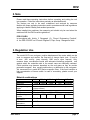
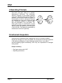
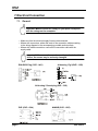
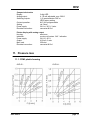
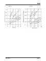
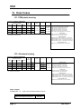
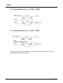
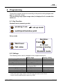
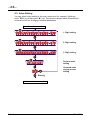
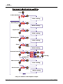
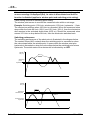
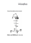
Operating Instructions
for
Oval Gear Flow Meter
Model: OVZ
OVZ
1. Contents
1.
2.
3.
4.
5.
6.
7.
Contents .................................................................................................... 2
Note ........................................................................................................................3
Regulation Use .......................................................................................... 3
Operating Principle ............................................................................... 4
Instrument Inspection................................................................................. 4
Mechanical Connection.............................................................................. 5
Electrical Connection ..................................................................................6
7.1. General .............................................................................................. 6
7.2. Electronics: ........................................................................................ 7
7.3. Analog Output .................................................................................... 7
7.4. Compact electronics: ......................................................................... 7
7.5. Pointer Indication with Analog output (....Z340) ................................. 8
8. Electronics Operation.................................................................................. 8
8.1. Frequency output ............................................................................... 8
8.2. Analog output ......................................................................... 8
8.3. Compact electronics ..........................................................................8
8.4. Pointer display (…..Z340) ................................................................. 8
9. Mechanical Operation .............................................................................. 10
10. Technical Information............................................................................... 10
11. Pressure loss ............................................................................................ 11
11.1. POM- plastic housing ................................ ........................... 11
11.2. Aluminum housing .......................................................................... 12
12. Order Codes .............................................................................................14
12.1. POM plastic housing ....................................................................... 14
12.2. Aluminum housing .......................................................................... 14
13. Maintenance ............................................................................................ 15
14. Dismantling / Installation ........................................................................... 15
15. Recommended spare parts...................................................................... 15
16. Dimensions .............................................................................................. 16
17. Declaration of Conformance .....................................................................19
Manufactured and sold by:
KOBOLD Instruments Inc.
1801 Parkway View Drive
Pittsburgh, PA 15205
Tel.: 412-788-2830
Fax: 418-788-4890
E-Mail: [email protected]
Website: www.koboldusa.com
page 2
OVZ 4-2013
OVZ
2. Note
Please read these operating instructions before unpacking and putting the unit
into operation. Follow the instructions precisely as described herein.
The devices are only to be used, maintained, and serviced by someone
familiar with these operating instructions and in accordance with local regulations
applying to Health & Safety and accident prevention.
When installed into machines, the measuring unit should only be used when the
machines fulfill the EWG-machine guidelines.
PED 97/23/EG
In accordance with Article 3 Paragraph (3), "Sound Engineering Practice",
of the PED 97/23/EC no CE mark. Diagram 8, Pipe, Group 1 dangerous fluids
3. Regulation Use
The model OVZ is an oval gear, positive displacement flow meter which can be
used to measure and monitor the flow rate of viscous liquid (min. 10 mm²/s
to max. 800 mm²/s); (max. viscosity 1000 mm²/s upon request). Only
measure clean, non-abrasive liquids with adequate lubricating properties, and
against which the materials used in the sensor case are chemically resistant.
Ferrite particles may become deposited on the oval gears as they do contain
permanent magnets, thus causing malfunctions, or destruction to the oval gears.
We recommend our model MFR series magnetic filters, if the liquid contains a
high concentration of ferrous solids. In case of uncertainty, please consult your
supplier.
Material combinations
Model
OVZ-..1.. OVZ-..2.. OVZ-..3..
OVZ-..4..
OVZ-..5..
Case
POM
POM
Aluminum Aluminum
Aluminum
Case cover
POM
PMMA
PMMA
PSU
Aluminum
Axle
304 Stainless steel
Rotating sensing
Ceramics (Hall sensor versions) stainless steel (inductive
targets
pickup versions)
Oval gears
POM
O-ring
Standard: NBR; option: FKM or EPDM
max. operating
145 PSI 145 PSI 232 PSI
232 PSI
580 PSI
pressure
max. medium
176 °F
temperature
max. ambient
140 °F
temperature
Filtration requirements max. 30 µm
OVZ 4-2013
page 3
OVZ
4. Operating Principle
The OVZ oval gear meter is a positivedisplacement flow meter. The measuring
element comprises of two toothed precision
oval gears, which are driven by the liquid inlet
pressure. As the liquid rotates the gears, a
fixed quantity of liquid is transported through
the chambers for every turn of the oval gear
pair. Permanent magnets or stainless steel
pins are embedded in the oval gears. The
rotary gear motion is converted to a pulse
signal by electrical sensors externally fitted
into the casing. The pulse count is a measure
of the flow rate. The signals are evaluated by
downstream electronics (optional).
5. Instrument Inspection
Instruments are inspected before shipping and sent out in perfect condition.
Should the damage to a device be visible, we recommend a thorough inspection
of the delivery packaging. In case of damage, please inform your parcel
service/forwarding agent immediately, since they are responsible for damages
during transit.
Scope of delivery:
• Oval gear meter model: OVZ
• Operating Instructions
page 4
OVZ 4-2013
OVZ
6. Mechanical Connection
Before installation:
• Make sure that the actual flow rate corresponds with the measuring range of
the meter.
• Make sure that the approved maximum operating pressure and operating
temperature of the meter is not exceeded.
• Remove all transport restraints and ensure that there are no pieces of
packaging left in the meter.
• Make sure that there are no welding beads, metal filings, or other pollutants, in
the piping. We strongly recommend that you install a suitable filter in series
(filtration ≤ 30 µm).
Installation:
• The OVZ may be installed in any position; the liquid may flow in both
directions.
• Inlet and outlet straight piping is not required.
• The connection threads may be sealed with sealing tape etc.
• When installing the meters, make sure that the connection threads are not
subjected to large pressure or tensile loads. We recommend that you
mechanically secure the inlet and outlet line approximately 50 mm from the
connections.
• If possible, you should check that the process connections are sealed and
leak- free after mechanical installation.
OVZ 4-2013
page 5
OVZ
7. Electrical Connection
7.1. General
Important! Make sure that the voltage in your plant correspond
with the voltage on the nameplate.
• Make sure that the electrical supply lines are disconnected.
• Meters with connectors: solder the ends of the connection cable according
to the wiring diagram in the accompanying portable socket-outlets.
• Meters with cable connections: connect the connection cable with the
supply cable.
Important! If the connections are incorrectly terminated on the
device, the sensor may be seriously damaged.
DIN-43650 Plug (OVZ-...l401)
Al-housing / Pg 9(OVZ-...l302)
Al-Housing / Round plug (OVZ-...l303)
PNP (OVZ-...l304)
page 6
NAMUR (OVZ-...l305)
OVZ 4-2013
OVZ
7.2. Frequency Output:
Frequency output (OVZ-...F300; ...F3x0)
7.3. Analog output (..L..)
3-wire (OVZ-....L343)
3-wire, DIN 43650-plug (OVZ-...L443)
+Vs
+Vs
n.c.
GND
GND
2
3
1 +Vs
+Vs
Signal
Out
Signal
4 Out
GND
GND
7.4. Compact electronics:
(..C30r, ..C30M, ..C34P, ..C34N)
see instruction manual supplement for compact electronics with frequency output.
OVZ 4-2013
page 7
OVZ
7.5. Pointer display (....Z340)
+Vs
n.c.
2
1 +Vs
Power
Plug M12
GND
GND
3
Signal
4 Out
mA
• Plug the portable socket-outlet into its mating connector on the meter.
8. Operation – Electronics
8.1. Frequency output
The instruments are pre-adjusted. After electrical connection they are ready for
operation.
8.2. Analog output
The instruments are pre-adjusted. After electrical connection they are ready for
operation.
8.3. Compact electronics
The instruments are pre-adjusted. After electrical connection they are ready for
operation.
For changing of setting, refer to operating manual for compact electronic with
frequency output.
8.4. Pointer display (....Z340)
The instruments are pre-adjusted. After electrical connection they are ready for
operation.
page 8
OVZ 4-2013
OVZ
9. Mechanical Operation
• To avoid pressure peaks, the fluid should flow slowly into the meter.
Important! Pressure peaks arising from a sudden influx of liquid,
caused by solenoid valves, ball valves etc, may seriously damage the
meter (water hammer!). Ensure that the sensor is always filled with
media when in the operating state.
Important! Vent the piping, to prevent large air bubbles in the sensor
chamber which may cause measuring errors, erratic flow reading,
and can possibly seriously damage the bearings.
10. Technical Information
Ambient temperature:
Medium temperature:
Max. pressure:
10 to 800 mm2/s
(option: 1000 mm2/s)
14 °F to 140 °F
14 °F to 176 °F
OVZ-..1, OVZ-..2: 145 PSI
OVZ-..3, OVZ-..4: 232 PSI
OVZ-..5 : 580 PSI
Accuracy:
± 2.5 % f. s.
Filter mesh size:
max. 30 µm
Material:
combination/case/cover
OVZ-..1.. / POM /POM
OVZ-..2.. / POM /PMMA
OVZ-..3.. / aluminum /PMMA
OVZ-..4.. / aluminum /PSU
OVZ-..5.. / aluminum /aluminum
oval gears: POM
axles: stainless steel 304
O-rings:
NBR; option: FKM, EPDM
Sensor targets:
oxide ceramic magnets
or stainless steel
Frequency range:
0.3-9 Hz to 2-57 Hz
Viscosity range:
OVZ 4-2013
page 9
OVZ
Electronics
Frequency output (...l401; ...l302; ...l303)
Power supply:
5-24 VDC
Power consumption:
typically 10 mA
Pulse output:
Hall effect sensor NPN
open collector, max. 15 mA
Electrical connection:
connector socket DIN 43650 (...I401)
aluminum adapter box with cable
connection (...I302)
aluminum cover box with circular
connector M12x1 (...I303)
Frequency output (...l304)
Power supply:
Power consumption:
Pulse output:
Electrical connection:
Frequency output (...l305)
Power supply:
Pulse output:
18-30 VDC
typically 10 mA
PNP, asymmetrical, open collector
max. 120 mA
2 m PVC cable
Electrical connection:
nominal 8.2 VDC
Namur, asymmetrical,
max. approx. 3.5 mA (typ. 0.5 mA)
2 m PVC cable
Frequency output (...F300)
Power supply:
Power consumption:
Pulse output:
Electrical connection:
24 VDC ± 20 %
10 mA
PNP, open collector, max. 25 mA
connector M12x1
Frequency output with frequency divider (...F3X0)
Power supply:
24 VDC ± 20 %
Power consumption:
15 mA
Pulse output:
PNP, open collector, max. 25 mA
Electrical connection:
connector M12x1
Divisional factor:
acc. to customer specification
Analog output (....L343, ...L443)
Power supply:
24 VDC ± 20 %
Output:
4-20 mA, 3-wire
Max. load:
500 ohm
Electrical connection:
connector M12x1 or DIN 43 650
Option:
plug-on display AUF-3000
(with DIN connector only)
page 10
OVZ 4-2013
OVZ
Compact electronics
Display:
Analog output:
Switching outputs:
Contact operation:
Setting:
Power supply:
Electrical connection:
3-digit LED
4...20 mA adjustable, max. 500 Ω
1 (2) semiconductor PNP or
NPN, factory setting
N/C, N/O programmable
via 2 keys
24 VDC ± 20 %, 3-wire
connector M12x1
Pointer display with analog output
Housing:
aluminum
Indication:
moving coil instrum. 240 ° indication
Power supply:
24 VDC ± 20 %
Output:
4-20 mA, 3-wire
Max. load:
250 ohm
Electrical connection:
connector M12x1
11. Pressure loss
11.1. POM- plastic housing
OVZ-02...
OVZ 4-2013
OVZ-04...
page 11
OVZ
OVZ-15...
OVZ-30...
11.2. Aluminum housing
OVZ-02...
page 12
OVZ-04...
OVZ 4-2013
OVZ
OVZ-15...
OVZ 4-2013
OVZ-30...
page 13
OVZ
12. Order Codes
12.1. POM plastic housing
(Example: OVZ-02 1 N2 N I401)
Rated measuring range (GPM)
(for different viscosities)
10 mm²/s
100 mm²/s
320 mm²/s
1)
800 m²/s
Pulses
Per
Gallon
Model
0.8 – 2.1
0.8 – 2.1
0.5 – 1.3
0.3 – 0.53
1546
OVZ-02..
0.11 – 2.6
0.11 – 2.6
0.8 – 2.1
0.4 – 1.1
848
OVZ-04..
0.26 – 6.6
0.26 – 6.6
0.26 – 6.6
0.11 – 2.6
199
OVZ-15..
0.42 – 10.6
0.25 – 6.34
106
OVZ-30..
0.42 – 10.6 0.42 – 10.6
1)
2)
Material/
cover
..1..= POM
..2..= PMMA
Connection
..G2..= G 1/4
..N2..= 1/4 NPT
..G2..= G 1/4
..N2..= 1/4 NPT
..G4..= G 1/2
..N4..= 1/2 NPT
..G5..= G 3/4
..N5..= 3/4 NPT
Gaskets
..N..= NBR
(standard)
..V..= FKM
..E..= EPDM
Electrical transducer
Frequency output
..I401= frequency output NPN, DIN connector 43650
..I302= frequency output NPN, cable connection
..l304= frequency output PNP, 2 m PVC cable
..l305= frequency output Namur, 2 m PVC cable
..F300= frequency output PNP, connector M12x1
..F3X0= frequency divider adjusted PNP, connector M12x1
Analog output
..L343= 4-20 mA output, 3-wire, M12x1connector
..L443= 4-20 mA output, 3-wire, DIN connector
Maximum pressure loss at maximum rated flow is 14.5 PSI
Hz=Pulse/Gallon x Gallon/Minute/60
Compact electronic*
..C30R= LED-display, 2xopen collector, PNP, connector M12x1
..C30M= LED-display, 2xopen collector, NPN, connector M12x1
..C34P= LED-display, 4-20 mA, 1x op.coll.,PNP,connector M12x1
..C34N= LED-display, 4-20 mA, 1xop.coll.,NPN, connector M12x1
Pointer indication, 240°*
..Z340= 240°-pointer indication,4.20 mA, connector M12x1
* Please specify flow direction in writing
12.2. Aluminum housing
(Example: OVZ-02 3 N2 N I401)
Rated measuring range (GPM)
(for different viscosities)
1)
Pulses
Per
Gallon
Model
10 mm²/s
100 mm²/s
320 mm²/s
800 mm²/s
0.8 – 2.1
0.8 – 2.1
0.07- 1.74
0.03 – 0.79
1499
OVZ-02..
0.11 – 2.6
0.11 – 2.6
0.11 – 2.64
0.07 – 1.19
768
OVZ-04..
0.26 – 6.6
0.26 – 6.6
0.24 – 6.08
0.13 – 3.30
176
OVZ-15..
0.42 – 10.6
0.42 – 10.6
0.34 – 8.85
0.21 – 5.28
98
OVZ-30..
1)
2)
Material/
cover
..3..= PMMA
..4..= PSU
..5..= Alu
Connection
..G2..= G 1/4
..N2..= 1/4 NPT
..G2..= G 1/4
..N2..= 1/4 NPT
..G4..= G 1/2
..N4..= 1/2 NPT
..G5..= G 3/4
..N5..= 3/4 NPT
Maximum pressure loss at maximum rated flow is 1 bar
Hz = Pulse/Gallon x Gallon/Min/60
Gaskets
..N..= NBR
(Standard)
..V..= FKM
..E..= EPDM
Electrical transducer
Frequency output
..I401= frequency output NPN, DIN connector 43650
..I302= frequency output NPN, cable connection
..l304= frequency output PNP, 2 m PVC cable
..l305= frequency output Namur, 2 m PVC cable
..F300= frequency output PNP, connector M12x1
..F3X0= frequency divider adjusted PNP, connector M12x1
Analog output
..L343= 4-20 mA output, 3-wire, M12x1connector
..L443= 4-20 mA output, 3-wire, DIN connector
Compact electronic*
..C30R= LED-display, 2xopen collector, PNP, connector M12x1
..C30M= LED-display, 2xopen collector, NPN, connector M12x1
..C34P= LED-display, 4-20 mA, 1x op.coll.,PNP,connector M12x1
..C34N= LED-display, 4-20 mA, 1xop.coll.,NPN, connector M12x1
Pointer indication, 240°*
..Z340= 240°-pointer indication,4-20 mA, connector M12x1
* Please specify flow direction in writing
Plug-on display
for Model OVZ... L4 ... (with 4-20 mA output and DIN-connector)
Description
3-digit LED, plug-connection DIN 43 650
3-wire, power supply with analog output
page 14
Order number
AUF-3000
OVZ 4-2013
OVZ
13. Maintenance
The meter requires no maintenance if the measured media is not contaminated.
Should it be necessary to clean the meter, the meter body cover can be easily
removed to gain access to, and clean, the inside of the meter body (see Sec.
12. Dismantling/Installation).
14. Dismantling / Installation
Dismantling:
•
•
•
•
Drain piping.
Loosen cover screws and remove cover and O-ring.
Mark the position of the gears relative to one another with a pencil.
Remove the pair of oval gears and clean parts with care; do not scratch the
sealing faces.
Caution: Do not remove the oval gears position marking!
Installation:
• Install the pair of oval gears; note identifying markings.
• Rotate gears a number of times: they should not disengage.
• Insert O-ring; replace meter body cover and firmly tighten screws crosswise.
15. Recommended spare parts
1.0 Pair of oval gears
2.0 NBR, FKM, or EPDM O-ring
3.0 POM, PMMA, PSU, or AL cover
Always specify the meter model when ordering spare parts.
OVZ 4-2013
page 15
OVZ
16. Dimensions
OVZ-...l401
OVZ-02...
OVZ-04...
OVZ-15...
OVZ-30...
G
[mm]
68
68
99
119
H
[mm]
68
68
99
119
..1..
45
49
71
84,5
..2..
45
49
73
87,5
F [mm]
..3/ 4..
43,5
47
71
86
..5..
41
44,5
66
79,5
H
[mm]
68
68
99
119
..1..
45
49
71
84,5
..2..
45
49
73
87,5
F [mm]
..3/ 4..
43,5
47
71
86
..5..
41
44,5
66
79,5
OVZ-...l302, OVZ-...l303
OVZ-02...
OVZ-04...
OVZ-15...
OVZ-30...
page 16
G
[mm]
68
68
99
119
OVZ 4-2013
OVZ
OVZ-...l304, OVZ-...l305
OVZ-02..
OVZ-04..
OVZ-15..
OVZ-30..
OVZ 4-2013
PNP
A [mm] B [mm]
21,5
13,5
21
14
19
16
17
18
NAMUR
A [mm] B [mm]
16,5
13,5
16
14
14
16
12
18
PNP/ NAMUR
G [mm] H [mm]
68
68
68
68
99
99
119
119
page 17
OVZ
OVZ-...L3...
OVZ-...F3...
OVZ-...L443 with AUF-3000
OVZ with frequency or analog output: overview
Description
OVZ-02 1 = POM
OVZ-02 2 = PMMA
OVZ-04 1 = POM
OVZ-04 2 = PMMA
OVZ-15 1 = POM
OVZ-15 2 = PMMA
OVZ-30 1 = POM
OVZ-30 2 = PMMA
Description
OVZ-02 3 = PMMA
OVZ-02 4 = PSU
OVZ-02 5 = ALU
OVZ-04 3= PMMA
OVZ-04 4 = PSU
OVZ-04 5 = ALU
OVZ-15 3= PMMA
OVZ-15 4 = PSU
OVZ-15 5 = ALU
OVZ-30 3= PMMA
OVZ-30 4= POM
OVZ-30 5= PMMA
page 18
Plastic housing (POM)
Dimension
Dimension
A
B
13
45
13
45
13.7
49
13.7
49
15.65
71
15.65
73
17.6
84.5
17.6
87.5
Dimension
C
68
68
68
68
99
99
119
119
Aluminum housing (ALU)
Dimension
Dimension
A
B
11.5
43.6
11.5
43.6
11.5
41.1
11.5
47
11.5
47
11.5
44.5
13.35
71
13.35
71
13.35
66
15.75
86
15.75
86
15.75
79.5
Dimension
C
68
68
68
68
68
68
99
99
99
119
119
119
OVZ 4-2013
OVZ
OVZ-…C3…
OVZ-…Z3…
OVZ with compact electronics: overview
Description
OVZ-02 1 = POM
OVZ-02 2 = PMMA
OVZ-04 1 = POM
OVZ-04 2 = PMMA
OVZ-15 1 = POM
OVZ-15 2 = PMMA
OVZ-30 1 = POM
OVZ-30 2 = PMMA
Description
OVZ-02 3 = PMMA
OVZ-02 4 = PSU
OVZ-02 5 = ALU
OVZ-04 3= PMMA
OVZ-04 4 = PSU
OVZ-04 5 = ALU
OVZ-15 3= PMMA
OVZ-15 4 = PSU
OVZ-15 5 = ALU
OVZ-30 3= PMMA
OVZ-30 4= POM
OVZ-30 5= POM
OVZ 4-2013
Plastic housing (POM)
Dimension
Dimension
A
B
19.525
45
19.525
45
16.95
49
16.95
49
21.125
71
21.125
73
23.2
84.5
23.2
87.5
Dimension
C
68
68
68
68
99
99
119
119
Aluminum housing (ALU)
Dimension
Dimension
A
B
19.525
43.6
19.525
43.6
19.525
41.4
19.525
47
19.525
47
19.525
44.5
21
71
21
71
21
66
23.025
86
23.025
86
23.025
79.5
Dimension
C
68
68
68
68
68
68
99
99
99
119
119
119
page 19
OVZ
17. Declaration of Conformance
We, KOBOLD Messring GmbH, Hofheim-Ts, Germany, declare under our
sole responsibility that the product:
Oval Gear Flow Meter
Model: OVZ-...
to which this declaration relates is in conformity with the standards noted below:
EN 50082-2
EMC General Immunity Requirements
a) Immunity against electrostatic discharges
(IEC 0801-2, ESD).
b) Immunity against fast transients.
(IEC 1000-4, BURST)
Also the following EWG guidelines are fulfilled:
2004/108/EC
EMC Directive
Hofheim, 16. Jan. 2007
page 20
H. Peters
General Manager
M. Wenzel
Proxy Holder
OVZ 4-2013
Operating Instruction
Supplement
for
Compact Electronics
Model:..C30R;..C30M
..C34P;..C34N
...C3...
1. Contents
1.
2.
3.
4.
5.
6.
Contents........................................................................................................2
Note ..............................................................................................................3
Electrical Connection ....................................................................................3
Programming ................................................................................................5
Maintenance ...............................................................................................12
Technical Information..................................................................................12
Manufactured and sold by:
Kobold Messring GmbH
Nordring 22-24
D-65719 Hofheim
Tel.: +49(0)6192-2990
Fax: +49(0)6192-23398
E-Mail: [email protected]
Internet: www.kobold.com
Seite 2
...C3... 07/04
...C3...
2. Note
This programming instruction is only a supplement to the operating
instruction for the sensor.
3. Electrical Connection
3.1. General
Attention! Make sure that the voltages in your plant correspond
with the instrument voltages
• Make sure that the supply wires are de-energized.
• Connect the supply voltage and evaluation of both output signals to the plug
connector PINs as shown in section 3.2 and 3.3.
• We recommend the use of wires with cross sectional area of min. 0,25 mm²
Attention! Incorrect wiring will lead to damage of the unit’s
electronics.
...C3... 07/04
Seite 3
...C3...
3.2. Compact Electronics: (..C30R, ..C30M)
Switch out 2
+ Vs
GND
2
GND
3
1
5
4
Switch out 1
3.3. Compact Electronics: (..C34P, ..C34N)
(0)4-20 mA
+ Vs
GND
2
GND
3
1
5
4
Switch out 1
Terminals 3 and 5 are linked internally and can therefore be used either for the
output signal or the power supply.
Seite 4
...C3... 07/04
...C3...
4. Programming
Connect the compact electronics according to the previous wiring diagram and
apply the specified voltage.
The measuring range (upper range value) is displayed for 3 seconds after
switch-on.
4.1. Key Function
Standard mode (measuring mode)
: pressing 3 sec.
set-up mode
: switchpoint/window point
Set-up mode
Anytime:
3 sec
: Next level
or 20 sec
no key pressing
: Set value
Standard mode
4.2. Settings
The following values can be changed in the compact electronics:
Switching point (SPo, SP1, SP2)
Hysteresis (HYS)
Window point (duo)
Filter (Filt)
Contact type (Con, Co1, Co2)
Start current (S-C)*
End current (E-C)*
Start current selection (SCS)
Change code (CCo)
Scale range
Factory setting
0 - 999
-199 - 0
Switching point ...999
1/2/4/8/16/32/64
N/O contact (no), N/C (nc)
or frequency (Fr)**
000 - 999
000 - 999
0-- (0 mA), 4-- (4 mA)
000 - 999
0.00
-0.00
--- (de-activated)
1
no (N/O contact)
000
Upper range value
4 mA
000
* Lower and upper range values of the flow rate are based on 0/4-20 mA.
** only for sensors with impulse output (e.g. DPE)
...C3... 07/04
Seite 5
...C3...
4.3. Value Setting
You can select Value setting in the main menu item (for example: Switching
point, "SPo") by pressing the "u" key. The structure shown below illustrates the
universal routine for changing individual parameters.
from the main menu item
1. Digit setting
2. Digit setting
3. Digit setting
Decimal point
setting
Choosed value
storing or new
setting
Storing
to the next main menu item
Seite 6
...C3... 07/04
...C3...
4.4. Set-up Mode
3 sec
Code entering
Code=
Value setting
Swichting
point 1
Value setting
Switching
point 2
Value setting
Hysteresis
Value setting
Filter
7 Levels
Contact 1
function
Contact 2
function
Value setting
N/O
N/C
Frequency*
Storing
N/O
Storing
Changing code
Value setting
*Only for sensors with impulse output
...C3... 07/04
Seite 7
...C3...
3 sec
Code entering
Code=
Value setting
Switching point
Value setting
Hysteresis
Value setting
Windowpoint
Value setting
Filter
7 levels
Value setting
Contact function
N/O
N/C
Frequency*
Start current
End current
7sec
Storing
Value setting
7sec
Value setting
*Only for sensors with impulse output
Seite 8
...C3... 07/04
...C3...
Analog output
choosing
0-20
mA
7sec
4-20
mA
Storing
Changing code
Value setting
4.5. Main Menu Items
Switching point
The switching point is entered in menu item "SPo, SP1, SP2". A value in the
range 000 to 999 may be chosen. A decimal point position is also assigned to
this value. The position of the decimal point can be set after the first, second or
last position (no decimal point). If the indicated value exceeds the set switching
point, then the electronics switches and energizes the LED.
If the hysteresis is equal to zero and the window point is de-activated, the
electronic switches back whenever the indicated value falls below the switching
point.
Hysteresis
After the switching point, hysteresis can be entered as a negative value in the
menu "HYS". The default hysteresis value is zero. However this can lead to
confused switching, when the measuring signal fluctuates around the switching
point or window point. This problem can be cured by increasing the hysteresis.
The hysteresis is based on the switching point and the window point (switching
point minus hysteresis; window point plus hysteresis).
Example: switching point 100 l/min; hysteresis: -2.5 l/min
The electronics switches when 100 l/min is exceeded and switches
back when the flow rate falls below 97.5 l/min.
Window point (duo point)
A window point "duo" (duo point) can be defined in addition to the switching
point. The window point must be greater than the switching point. The measured
value can be monitored within a set range by means of the window point and
switching point. The switching point marks the lower end of the range of values
and the window point the upper end.
...C3... 07/04
Seite 9
...C3...
If the window point (duo point) is lower than or equal to the switching point,
an error message is displayed (Er4), its value is then deleted and thus its
function is disabled (applies to window point and switching point setting).
Value setting is similar to switching point setting.
The window point serves to monitor the measured value within a set range.
Example: Switching point: 100 l/min; window point: 150 l/min; hysteresis: -1 l/min
The electronics switches when 100 l/min is exceeded. When the measured value
stays within the limits 99 l/min (100-1) and 151 l/min (150+1), then the electronics
also remains in the activated switch state (LED on). Should the measured value
exceed 151 l/min or drop below 99 l/min, then the electronics switches back.
Switching performance
The switching performance of the electronics is illustrated in the diagram below.
The contact closes (N/O contact) when the switching point is exceeded or when
the value drops below the window point. It opens when the window point plus
hysteresis is exceeded or when the value drops below the switching point minus
hysteresis. The switch state of the electronics is indicated by an LED.
Display
bar (°C)
LED on
Switching
point
Hysteresis
Time / t
Display
bar (°C)
LED on
Hysteresis
Window point
LED on
Switching point
Hysteresis
Time / t
Seite 10
...C3... 07/04
...C3...
Filter
The filter function "Filt" generates the sliding average value from the measured
values. The following values are available (see section 6.2 Settings):
1 / 2 / 4 / 8 / 16 / 32 / 64
The filter value determines the dynamic behaviour of the indicated value: high
values result in a slow display response. The filter is disabled if a filter value of
"1" is selected. In other words, the indicated value is equal to the unfiltered
measured value.
The integrated step detector responds to a measured-value step change greater
than approximately 6.25% of the upper range value. When a measured-value
step change is detected, the actual measured value is displayed immediately.
Contact Model
The function of the transistor switching output is set in menu item "Con, Co1 or
Co2". The switching function switches from
no - N/O contact to
nc - N/C to
Fr – frequency
(Con and Co1 only and
for sensors with impulse
output)
and back.
N/O contact means: contact closes when switching point is exceeded
N/C means: contact opens when switching point is exceeded
Frequency means: frequency output synchronized with vane frequency
Current output
The current output is selected in menu items
"S-C" Start current indicated value < > 0(4) mA
"E-C" End current indicated value < > 20 mA
"SCS" Start current selection (0-20 mA or 4-20 mA).
The indicated value at which 0(4) mA flow is entered in menu item Start current.
The indicated value at which 20 mA flow is entered in menu item End current.
Change Code
The change code option "CCo" secures the unit against unauthorised tempering.
If the code is different from 000, the user must input the code immediately after
entering the adjustment mode.
...C3... 07/04
Seite 11
...C3...
5. Maintenance
Work on the electronics should only be carried out by the supplier, otherwise the
guarantee is nullified.
6. Technical Information
Display:
Display case:
Analogue output:
Transistor output:
Frequency output:
Max. switching current:
Function:
Setting:
Supply:
Electrical connection:
Seite 12
3-segment LED
stainless steel
(0)4 - 20 mA scalable (...C34 only)
1 (2) semiconductor PNP or NPN,
set at the factory.
1 transistor output
vane frequency (see sensor)
300 mA
N/C / N/O contact programmable
with 2 buttons
24 VDC ±20%, 3-wire technology
plug connector M12x1
...C3... 07/04