1
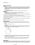
Figure 8
Driver Side Shown - Top View
Frame
Axle
Bend in towards the center
for tire clearance
20. Drill the two small hole in the front face of the OE track bar bracket to 7/16”. Drill the single small hole in the back face of the bracket to
1/2”. Place track bar relocation bracket over the OE mount. Install the provided (69) crush sleeve (0.750 x 0.083 x 1.375) between bracket
and OE pocket. (Fig 9A/B)
Figure 9A
Figure 9B
21. Attach track bar bracket to OE mount with 7/16” x 1” bolts, washers, and nuts in the front two holes. Attach the bracket to the back hole
with a 1/2” x 1” bolt, washer and square nut. Use 9/16” x 3” bolt, washers and nut through the OE track bar position. Do not hook up the
track bar at this time. Note: All hardware is located in bolt pack 562.
22. Tighten 9/16” hardware to 95 ft-lbs, and 7/16” hardware to 45 ft-lbs.
23. Position the new track bar support bracket on the back side of the track bar bracket by aligning the large hole in the bracket to the top hole
in the already installed track bar bracket. The tabs on the support bracket will set against the coil mount (top in the front and inside surface
in the back). Install the provided 9/16” x 3-1/2” bolt (BP 645) through the track bar bracket and support bracket to help keep the support in
place. (Fig 10)
Figure 10
8 | 014446