1
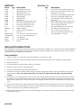
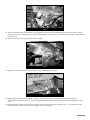
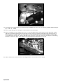
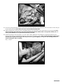
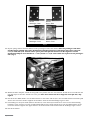
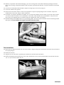
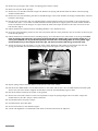
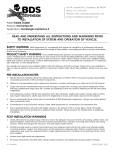
491 W. Garfield Ave., Coldwater, MI 49036
Phone: 517-279-2135
Web/live chat: www.bds-suspension.com
E-mail: [email protected]
Part#: 124021
Product: Spring Conversion Suspension System
Application: 1976-1986 Jeep CJ5, CJ7, CJ8
Read and understand all instructions and warnings prior
to installation of system and operation of vehicle.
SAFETY WARNING
BDS Suspension Co. recommends this system be installed by a professional technician.
In addition to these instructions, professional knowledge of disassembly/ reassembly procedures and post installation
checks must be known.
PRODUCT SAFETY WARNING
Certain BDS Suspension products are intended to improve off-road performance. Modifying your vehicle for off-road use may result in the vehicle handling differently than a factory equipped
vehicle. Extreme care must be used to prevent loss of control or vehicle rollover. Failure to drive your modified vehicle
safely may result in serious injury or death. BDS Suspension Co. does not recommend the combined use of suspension
lifts, body lifts, or other lifting devices.
You should never operate your modified vehicle under the influence of alcohol or drugs. Always drive your modified vehicle at reduced speeds to ensure your ability to control your vehicle under all driving conditions. Always wear your seat
belt.
Pre-Installation Notes
1. Special literature required: OE Service Manual for model/year of vehicle. Refer to manual for proper disassembly/
reassembly procedures of OE and related components.
2. Adhere to recommendations when replacement fasteners, retainers and keepers are called out in the OE manual.
3. Larger rim and tire combinations may increase leverage on suspension, steering, and related components. When
selecting combinations larger than OE, consider the additional stress you could be inducing on the OE and related
components.
4. Post suspension system vehicles may experience drive line vibrations. Angles may require tuning, slider on shaft
may require replacement, shafts may need to be lengthened or trued, and U-joints may need to be replaced.
5. Secure and properly block vehicle prior to installation of BDS Suspension components. Always wear safety glasses
when using power tools.
6. If installation is to be performed without a hoist, BDS Suspension Co. recommends rear alterations first.
7. Due to payload options and initial ride height variances, the amount of lift is a base figure. Final ride height
dimensions may vary in accordance to original vehicle attitude. Always measure the attitude prior to beginning
installation.
POST-INSTALLATION WARNINGS
1. Check all fasteners for proper torque. Check to ensure for adequate clearance between all rotating, mobile, fixed, and
heated members. Verify clearance between exhaust and brake lines, fuel lines, fuel tank, floor boards and wiring
harness. Check steering gear for clearance. Test and inspect brake system.
2. Perform steering sweep to ensure front brake hoses have adequate slack and do not contact any rotating, mobile
or heated members. Inspect rear brake hoses at full extension for adequate slack. Failure to perform hose check/
replacement may result in component failure. Longer replacement hoses, if needed can be purchased from a local
parts supplier.
3. Perform head light check and adjustment.
4. Re-torque all fasteners after 500 miles. Always inspect fasteners and components during routine servicing.
rev. 5/21/2013
124021 Page 1
PARTS LIST
Part #
Qty Description
01451
1
Spring Plate (drv front)
01452
1
Spring Plate (pass front)
01453
1
Spring Plate (drv rear)
01454
1
Spring Plate (pass rear)
01455
2
Spring Hanger
01456
2
Spring Hanger
01457
2
Link Spacer
01492
1
Driver's side spring hanger spacer
01493
1
Pass side spring hanger spacer
01499
2
Steering box drop spacer (1/4")
37-1
4
3/4" x 0.109" x 2.985 Sleeve
3625RB
8
Hanger Bushing
39-1
1
0.875 x 0.120 x 0.750 Sleeve
714
1
Bolt Pack
122120634R7
1/2" x 2-1/2" x 6-3/4" Round U-bolt
123000634R1
1/2" x 3" x 6-3/4" Round U-bolt
N12FH
16
1/2" High Nut
W12S
16
1/2" SAE flat washer
342701 1Loctite
Bolt Pack 714
Qty
4
2
5
3
18
2
2
4
6
6
1
1
1
Description
7/16"-14 x 1-1/4" bolt grade 8 yellow zinc
12mm-1.75 x 30mm bhshcs (button head
bolt) grade 5 - clear zinc
7/16"-14 x 1-1/2" bolt grade 8 yellow zinc
7/16"-14 x 2" bolt grade 8 yellow zinc
7/16" SAE flat washer thru-hardened
yellow zinc
7/16"-14 prevailing torque nut yellow zinc
12mm-1.75 Prevailing Torque Nut clear
1/4"-28 straight grease zerk
5/8"-18 prevailing torque nut clear zinc
5/8" SAE flat washer clear zinc
1/8" x 1-1/4" cotter pin clear zinc
1/4"-20 x 1-3/4" grade 5 clear zinc bolt
1/4" SAE Washer - clear zinc
INSTALLATION INSTRUCTIONS
Note: Installation of YJ specific lift springs will increase the wheel base slightly over 1”. These instructions detail installation
of spring hangers, spring plates, and related parts. Shackles and leaf springs are not included in this kit; refer to manufactures instructions for installation of these items.
Front Installation
1. Park the vehicle on a clean, flat surface and block the rear wheels for safety.
2. Raise the front of the vehicle and support with jack stands under the frame rails, behind the spring hangers.
3. Remove the wheels.
4. To aid installation of front brackets remove front bumper.
5. Support the front axle with a hydraulic jack.
6. Remove the OE shocks. Retain the shock hardware.
7. Disconnect the sway bar links from the sway bar and the spring plates. Retain the upper hardware, discard the
lower hardware. Note: The sway bar link stud at the sway bar is tapered and will require and pickle fork for
removal.
8. If installing a new dropped pitman arm, disconnect the drag link from the pitman arm. Retain hardware. Remove
the pitman arm nut and remove the pitman arm with an appropriate puller (note the indexing of the pitman arm).
Install the new pitman arm, indexed the same as the original, and fasten with the OE hardware and torque to OE
specs.
9. Disconnect the driver’s side spring u-bolts and remove along with the OE spring plate. Discard u-bolts and plate.
10. Raise the axle just off the spring. Disconnect the front shackles and rear hanger bolt. Remove the spring from the
vehicle. Discard the spring, shackles and hanger bolt.
11. Remove the two bolts mounting the front shackle hanger to the frame and remove the hanger. Discard the hanger
and hardware. (Fig 1)
Page 2 124021
Fig 1
12. The forward-most frame crossmember rivet (original covered by the OE shackle hanger) must be removed. Using a
grinder or air chisel, remove the head of the rivet and knock the body of the rivet from the frame with a hammer and
punch. (Fig 2)
13. Remove lower rear steering box bracket bolt (*) (Fig 2)
(*)
Fig 2
14. Support steering box from below and remove 2 upper mounting bolts (Fig 3)
Fig 3
15. Slightly lower steering box and install ¼” spacers on top of steering box mounting bracket and underneath
crossmember. Install new 7/16” x 1-1/2” bolts through original mounting points and spacers. Do NOT tighten at this
time.
16. Install (#01492) driver’s side steering box spacer above steering box bracket. Install 7/16” x 1-1/2” bolt with 7/16”
SAE washer at rear most location, do not tighten at this time. (Fig 4)
124021 Page 3
#01492
Fig 4
17. Coat with grease and install the provided bushings (3625RB) and sleeves (37-1) in the four provided shackle hangers
[(2) - 01455, (2) - 01456].
18. Install the provided grease fittings in the threaded holes in the hangers.
19. Install a 01455 driver’s side hanger with 7/16” x 2” bolts and SAE washers from bolt pack #714. Mount the hanger
with the forward hole aligned with the rivet hole and rear hanger hole with the old front hanger mount (See Fig 5,
old rear mount is no longer used). Use loctite on the rear bolt and attached the front bolt through the frame with a
7/16” SAE washer and lock nut. Ensure that the hanger is square to the side of the frame and tighten all mounting
hardware to 60 ft-lbs. (Fig 4 / Fig 5) Torque upper steering box mounting bolts to 60 ft-lbs.
7/16" x 2"
7/16" x 1-1/2"
Fig 5
20. Follow manufactures instructions for installing shackles. Leave hardware loose. (Fig 6)
Page 4 124021
Fig 6
21. Clean the spring mounting surface on the axle and ensure that the center pin hole is free of corrosion so that the pin
head with fit properly. Note: Take care not to over-extend the brake lines.
22. Follow manufactures instructions for installing springs. Leave hardware loose until vehicle is on the ground. Note:
Some YJ springs will come with a tall center pin head that will not work in OE CJ axle perches. New 5/16” x 4”
center pins (#228002) can be purchased separately if needed.
23. Attach the spring to the axle with ½” x 2-1/2” wide u-bolts, high nuts and washers in conjunction with the new
01451 spring plate (see identification figures). Snug but do not tighten u-bolts. Note: On the passenger’s side bracket
(#01452) the top differential support web may need to be ground slightly to accept the new u-bolt position as a
result of using the wider YJ spring.
(Fig 7 / Fig 8)
Fig 7
124021 Page 5
#01454
Passenger—Rear
#01453
Driver—Rear
#01452
Passenger—Front
#01451
Driver—Front
Fig 8
24. Repeat spring removal and installation on the passenger’s side of the vehicle. Note: The passenger’s side front
shackle hanger (#01456) will require installation of (#01493) passenger’s side hanger plate spacer and 7/16”
x 1-1/2” bolts with 7/16” washers. These spacer plates will provide clearance for the original or certain
aftermarket bumpers to be installed. A ½” x 2-1/2 and ½” x 3-1/4” wide u-bolts are required on the passenger’s
side. (Fig 9)
#01493
#01456
7/16" x 1-1/2"
Fig 9
25. With both sides complete, install the drag link to the pitman arm if it was removed. Attach the tie rod with the OE
nut and torque to 50 ft-lbs. Install new cotter pin. Note: Never loosen the nut to align the cotter pin hole, only
tighten.
26. Install the new BDS shocks. Use the OE hardware at the frame and the 5/8” nuts and SAE washers from bolt pack
#714 at the new lower mounts. Tighten the hardware until the shock bushings begin to swell.
27. If installing new sway bar links (solid or disconnect) or the OE sway bar links do so now. Use the OE mounting
hardware at the sway bar. Use the provided 01457 link spacers along with the 5/8” nuts and SAE washers at the
new lower mounts. Tighten the upper mount to 30 ft-lbs and the lower mount until the bushings begin to swell.
28. Install the wheels.
Page 6 124021
29. With the suspension unloaded and hanging, cycle the steering lock to lock while manually spinning the wheels.
Inspect the steering, suspension and drive line for proper operation and clearance. Pay close attention to the brake
lines.
30. On narrow track models with OE wheels, adjust steering stops as necessary. (Fig 10)
31. Lower the vehicle to the ground.
32. Bounce the front of the vehicle to settle the suspension. Torque the spring hanger bolts to 90 ft-lbs. Torque the
shackle bolts to 50 ft-lbs. Torque u-bolts to 85 ft-lbs.
33. If transfer case drop kit #124000 is installed, do so at this time. Remove the three bolts on one side of the transfer
case that retain the transfer case crossmember to the frame. This will allow the crossmember to drop about one
inch. Insert the supplied spacers and fasten with the supplied 3/8” bolts and washers.
34.Reinstall bumper with OE hardware at top mounting points. Use new button head bolts at lower mounting location
(bolt pack #714) Note: Washer not required on button head side of bolt.
FIG. 10
Rear Installation
35. Block the front wheels and raise the rear of the vehicle. Support with jack stands under the frame rail just ahead of
the spring hangers.
36. Remove the wheels.
37. Support the rear axle with a hydraulic jack. Remove the shocks. Retain hardware.
38. Remove brakeline junction block above axle tube. Install #39-1 sleeve under junction block and reattach with new
1/4” x 1-3/4” bolt and washer. (Fig 11)
FIG. 11
124021 Page 7
39. Remove the passenger’s side u-bolts and spring plate from the vehicle.
40.Raise the axle just off the springs.
41. Remove the rear shackle and front hanger bolt. Remove the spring and shackle from the vehicle. Discard spring,
shackle and hardware.
42. Remove the two bolts mounting the OE rear shackle hanger to the frame. Remove the hanger and hardware. Discard
hardware and hanger.
43. Install the new passenger’s side rear (#01455) hanger (with bushings and sleeves installed) to the original hanger
location with 7/16” x 1-1/4” bolts and SAE washers from bolt pack #714. Support plate is located toward outside of
frame rail. Ensure that the hangers are square with the frame and torque the bolts to 60 ft-lbs. Use loctite on the
bolt threads. (Fig 9)
44.Follow manufactures instructions for installing shackles. Leave hardware loose.
45. Clean the spring mounting surface on the axle and ensure that the center pin hole is free of corrosion so that the pin
head with fit properly.
46.Follow manufactures instructions for installing springs. Leave hardware loose until vehicle is on the ground. Note:
Some YJ springs will come with a tall center pin head that will not work in OE CJ axle perches. New 5/16” x 4”
center pins (#228002) can be purchased separately if needed. Note: If installing shims to correct pinion angle,
attach shim directly to the leafpack with center pin. The thick end of the shim will go toward the front.
47. Attach the spring to the axle with ½” x 2-1/2” wide u-bolts, high nuts and washer in conjunction with the new
spring plate (#01454) (see identification figure). Snug but do not tighten u-bolts. (Fig 8 / Fig 12)
FIG. 12
48.Repeat spring removal and installation on the driver’s side of the vehicle.
49. Install the new BDS shocks. Use the OE hardware at the frame and the 5/8” nuts and SAE washers from bolt pack
#714 at the new lower mounts. Tighten the hardware until the shock bushings begin to swell.
50. Install the wheels and lower the vehicle to the ground.
51. Bounce the front of the vehicle to settle the suspension. Torque the spring hanger bolts to 90 ft-lbs. Torque the
shackle bolts to 50 ft-lbs. Torque u-bolts to 85 ft-lbs.
52. Check all hardware for proper torque.
53. Check hardware after 500 miles.
54.Grease front and rear new shackle hangers.
55. A front end alignment is recommended. The front toe measurement must be adjusted.
Page 8 124021