1
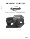
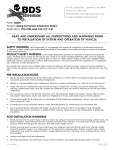
Part#: 024203
2” Coil Spring Spacer Kit
Jeep Wrangler JK 4WD | 2007-2014
Rev. 031314
491 W. Garfield Ave., Coldwater, MI 49036 . Phone: 517-279-2135
Web/live chat: www.bds-suspension.com . E-mail: [email protected]
Read And Understand All Instructions
And Warnings Prior To Installation Of
System And Operation Of Vehicle.
Your truck is about to be fitted with the best suspension system on the market today. That means you will be driving the
baddest looking truck in the neighborhood, and you’ll have the warranty to ensure that it stays that way for years to come.
Thank you for choosing BDS Suspension!
BEFORE YOU START
BDS Suspension Co. recommends this system be installed by a professional
technician. In addition to these instructions, professional knowledge of
disassembly/ reassembly procedures and post installation checks must be
known.
FOR YOUR SAFETY
Certain BDS Suspension products are intended to improve off-road
performance. Modifying your vehicle for off-road use may result in the
vehicle handling differently than a factory equipped vehicle. Extreme care
must be used to prevent loss of control or vehicle rollover. Failure to drive
your modified vehicle safely may result in serious injury or death. BDS
Suspension Co. does not recommend the combined use of suspension lifts,
body lifts, or other lifting devices. You should never operate your modified
vehicle under the influence of alcohol or drugs. Always drive your modified
vehicle at reduced speeds to ensure your ability to control your vehicle under
all driving conditions. Always wear your seat belt.
BEFORE INSTALLATION
• Special literature required: OE Service Manual for model/year of vehicle.
Refer to manual for proper disassembly/reassembly procedures of OE and
related components.
Visit 560plus.com for more information.
In an effort to reduce the risk of rollover crashes the National
Highway Traffic Safety Administration (NHTSA) established the
Federal Motor Vehicle Safety Standard (FMVSS) No. 126 requiring all new passenger vehicles under 10,000
lbs GVWR include an electronic stability
control (ESC) system as standard equipment.
Effective August 2012 this law requires aftermarket products to be compliant with these
same standards.
• Adhere to recommendations when replacement fasteners, retainers and
keepers are called out in the OE manual.
• Larger rim and tire combinations may increase leverage on suspension,
steering, and related components. When selecting combinations larger
than OE, consider the additional stress you could be inducing on the OE
and related components.
• Post suspension system vehicles may experience drive line vibrations.
Angles may require tuning, slider on shaft may require replacement, shafts
may need to be lengthened or trued, and U-joints may need to be replaced.
• Secure and properly block vehicle prior to installation of BDS Suspension
components. Always wear safety glasses when using power tools.
• If installation is to be performed without a hoist, BDS Suspension Co.
recommends rear alterations first.
• Due to payload options and initial ride height variances, the amount of lift
is a base figure. Final ride height dimensions may vary in accordance to
original vehicle attitude. Always measure the attitude prior to beginning
installation.
BEFORE YOU DRIVE
Check all fasteners for proper torque. Check to ensure for adequate clearance
between all rotating, mobile, fixed, and heated members. Verify clearance
between exhaust and brake lines, fuel lines, fuel tank, floor boards and wiring
harness. Check steering gear for clearance. Test and inspect brake system.
2 | 024203
FITMENT GUIDE
33x12.50 on 16x8 with 4.5” backspacing
See troubleshooting information notes
Perform steering sweep to ensure front brake hoses have adequate slack and
do not contact any rotating, mobile or heated members. Inspect rear brake
hoses at full extension for adequate slack. Failure to perform hose check/
replacement may result in component failure. Longer replacement hoses, if
needed can be purchased from a local parts supplier.
Perform head light check and adjustment.
Re-torque all fasteners after 500 miles. Always inspect fasteners and
components during routine servicing.
024203 Box Kit
Part #
Qty
024203 Box Kit
Description
768
1
Bolt Pack
1/4"- 20 x 3/4 bolt
02531BK
2
Front Coil Spring Spacer
2
02533BK
2
Rear Coil Spring Spacer
2
1/4"- 20 nylock nut
4
1/4" USS washers
1
Bolt Pack
01828
4
Octagon Cams
01928B
2
Rear Bump Stop Spacer
3296
2
3" dia x 2" tall bump stop spacer
4
5/16"-18 x 1-1/4" bolt
Rear Brake Line Drop Bracket
8
5/16" SAE washer
4
5/16"-18 prevailing torque nut
2
3/8"-16 x 3" bolt
4
3/8" USS washer
2
3/8"-16 prevailing torque nut
SBLA
2
751
tROUBLESHOOTING INFORMATION FOR YOUR VEHICLE
1.
Removing the OE spring isolators with result in a 1” lift if desired.
2.
BDS 124408 rear track bar or 124308 rear track bar relocation is recommended if using factory wheels.
Will fit RHD models.
INSTALLATION INSTRUCTIONS
1.
Park the vehicle on a clean, flat surface and block the rear wheels for safety.
2.
Measure from the center of the wheel up to the bottom edge of the wheel opening
3.
LF______ RF______ LR______ RR______
Disconnect the front track bar from the axle. Retain mounting bolt. (Fig 1)
024203 | 3
Figure 1 - left hand drive shown
4.
Raise the front of the vehicle and support the frame with jack stands behind the front lower control arm pockets.
5.
Remove the wheels.
6.
Support the front axle with a hydraulic jack. Remove the front shocks from the vehicle. Retain lower mounting hardware.
7.
Disconnect the sway bar links from the axle retain hardware.
8.
Lower the front axle and remove the coil springs from the vehicle.
9.
Make a mark in the center of the lower coil spring mount pad. Drill a 3/8” hole at the mark. This hole will be used to attach the provided
bump stop extension to the axle. (Fig 2)
Figure 2
10. Place a provided bump stop spacer (3296) inside one of the springs. Install the spring in the vehicle with new spring spacer on the top of
the spring. Make sure the spring is seated properly in the axle mount. The OE upper spring isolator should be reinstalled with the spacer to
net the full 2” of lift.
11. Attach the bump stop extension to the axle through the hole that was drilled earlier using a 3/8” x 3” bolt, nut and 3/8” USS washers (BP
751). Torque bolt to 30 ft-lbs. Repeat the spring spacer/bump stop installation of the other side of the vehicle.
12. Install the new shocks with the OE lower hardware and new upper bushings/hardware. Torque the lower bolt to 60 ft-lbs and the upper nut
until the bushings begin to swell.
13. Reconnect the sway bar links to the axle. Torque OE hardware to 55 ft-lbs.
14. With the front axle still support with a jack, remove the passenger’s side lower control arm bolt at the axle. The OE lower control arm
mounts are perforated from the factory so that they can be changed to slots for alignment cams. The perforated sections must be removed
to accepted the new cam lock plates (supplied in kit #1243). Special tools are made to perform this operation but are not necessary. The
perforated sections can be removed with a rotary grinding tool, chisel or a combination of both. If the section is going to be removed with
a die grinder, remove only the rear section of the slot. (Fig 3)
4 | 024203
Figure 3
15. When the perforated sections are removed from the lower control arm mount, reinstall the control arm to the axle with the factory bolt
with octagon washers with the bolt as far rearward in the slot as possible. Just snug the cam hardware so that the cam washers are retained
within the stops. Final cam bolt torque will be completed with the weight of the vehicle on the suspension. (Fig 4)
Figure 4
16. Repeat cam bolt installation on the driver’s side.
17. Install the wheels and torque lug nuts to manufacturer’s specifications.
18. Lower the vehicle to the ground and bounce the front to settle the suspension. Center the cams and torque the front cam bolts to 95 ft-lbs.
19. Reattach the front track bar to the axle with the OE hardware. Have an assistant turn the steering wheel to aid in aligning the track bar bolt.
Torque the track bar bolt to 100 ft-lbs.
Rear Installation
1.
Block the front wheels for safety.
2.
Disconnect the rear track bar from the axle. Retain hardware.
3.
Raise the rear of the vehicle and support the frame with jack stands in front of the lower control arm mounts.
4.
Remove the wheels.
5.
Remove the shocks. Retain the upper and lower mounting hardware.
6.
Disconnect the sway bar links from the axle. Retain hardware.
7.
Disconnect brake line brackets from the frame, save bolts (Fig 5).
024203 | 5
Figure 5
8.
Lower the axle and remove the rear springs.
Do not overextend the brakelines or ABS wires. It may be necessary to remove these from their retaining clips temporarily.
9.
Install the rear spring in the vehicle with the provided spring spacer on the top. Make sure to install the OE upper spring isolator as well to
net the full 2” of lift. Raise the axle to slightly compress the spring.
10. Install the new shocks with the OE hardware.
There is a spacer washer that must be placed on one side of the lower shock mounting sleeve. This will allow for proper compression of
the bushing. Tighten upper mounting hardware to 30 ft-lbs, and lower hardware to 55 ft-lbs.
11. Install the provided bump stop spacers on the axle using the existing holes in the axle bump stop pad. Fasten the bump stop spacer to the
axle with 5/16” x 1-1/4” bolts, nuts and 5/16” SAE washers (BP 751). Torque bolts to 20 ft-lbs. (Fig 6)
Figure 6
12. Install brakeline relocation brackets to the original brake line mounting point on the frame. Attach the bracket with the factory bolt. Attach the brake line to the INSIDE surface of the drop bracket with a 1/4” x 3/4” bolt, nut and washers (Fig 7). Torque hardware to 10 ft-lbs.
6 | 024203
Figure 7
13. Reinstall wheels and torque to factory specifications. Lower vehicle to ground.
14. Reconnect the track bar to the axle with the OE hardware. Torque hardware to 100 ft-lbs.
15. Double check all hardware for proper torque.
16. Have a front end alignment performed to correct caster angle.
17. Check all fasteners after 500 miles and at regularly scheduled maintenance intervals.
Thank you for choosing BDS Suspension.
For questions, technical support and warranty issues relating to this BDS Suspension product, please contact your distributor/installer
before contacting BDS Suspension directly.
024203 | 7