1
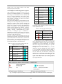
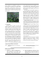
Article citation info:
CHWIST, M., ZYCH, M., JAMROZIK, A. Error analysis of the engine control unit in trucks diagnosis. Combustion Engines. 2013, 154(3),
915-923. ISSN 0138-0346.
PTNSS–2013–SC–170
Mariusz CHWIST
Michał ZYCH
Arkadiusz JAMROZIK
Error analysis of the engine control unit in trucks diagnosis
Abstract: Today an effective control of the work a car is possible thanks to a diagnostic tester which works
on OBDII/EOBD systems. In this paper functions of diagnostic devices for trucks were presented and we can see
a servicing test with diagnostic computer system. Damaged engine drivers were analyzed, for example errors
registered in service station.
Keywords: On-Board Diagnostic OBD, heavy duty vehicles, drive unit
Analiza błędów sterownika silnika w diagnostyce pojazdów ciężarowych
Streszczenie: Obecnie skuteczna kontrola pracy pojazdu samochodowego jest możliwa dzięki wykorzystaniu
testerów diagnostycznych pracujących w oparciu o system OBD II/EOBD. W pracy przedstawiono funkcje
diagnoskopów do pojazdów ciężarowych oraz pokazano przebieg badania serwisowego z zastosowaniem
komputerowego systemu diagnostycznego. Poddano analizie wybrane awarie sterownika silnika, na przykładzie
zarejestrowanych błędów w stacji obsługi pojazdów.
Słowa kluczowe: system diagnostyki pokładowej OBD, pojazdy ciężarowe, jednostka napędowa
We have to register this parameter if we want to
correct OBD II system: engine load, engine temperature, speed rotation, pressure in intake manifold
fuel pressure, supply voltage, AFR of the mixture,
correction rate time of opening injectors, vehicle
speed, course of the vehicle and information about
defect. We have to know that basic notion used in
on-board diagnostic of a vehicle is “monitor”. It is a
diagnostic procedure which is controlled by a central computer and it uses hardware and program. It
stores the result of the test which has been done
doing and it informs the user about the defect. It is
true that one monitor serves only one subsystem (or
component), so the amount used by monitor depends on the type of engine. We are marking out
monitors [16]:
- continuous (they watch above elements and components which are controlled “all time” in drive
time),
- conditional (in this elements are necessary longer
time to identify defect – longer time to observation).
Circuit OBD II/EOBD about which we talk use
two types of codes [22]:
- type A (errors that are responsible for increase in
exhaust gas toxic components and next causes turn
on control indicator immediately after error),
- type B (also they cause increase in exhaust gas
toxic components but slower than in type A indicator is turning on when error will be twice time).
If we want to turn off the lamp, we will have to
delete error or delete error code in computer
memory but only we uses diagnostic device or turn
off power which supply driver.
1. Introduction
The progress of today’s motorization means improvement in efficiency of internal-combustion
engines and reduction of emission harmful substances to the air [1-10]. Today’s constructors face
these requirements and they are restricted with onboard diagnostic systems OBDII and EOBD.
Standard OBD (On-Board Diagnostic) was introduced in 1996 in USA and was announced as a
global standard in 2000. It forced manufacturers to
build on-board diagnostic systems to every type of
car – passenger or trucks. The essential function of
these systems, is measurement and monitoring of
the basic parameters of a powertrain Above all
there are critical emission parameters (they affect
indirectly or directly the increasing emission from
the exhaust system or fuel supply system). The
priority for OBD system is elimination of many onboard systems measuring and diagnosing and replacing it with one universal and unified on-board
system. Due to this system it is possible to control
and diagnostic a drive unit and all vehicles. A European counterpart of OBD or OBDII system is
system EOBD (European On-Board Diagnostic)
[11-21].
Main assumptions of OBD II system are:
- the necessity to inform the driver with MIL lamp
about the problems with emission of toxic components,
- the necessity to equip vehicles with electronic
circuits which check if all the sensors combined
with the driver are correct (errors are saved in
memory ECU),
- the collection of information which is saved in the
driver with a possibility to read it.
915
Fig. 1. Tasks OBD II system [11]
Maintaining optimal
thermal conditions in
Airtronic D2/D4
the cargo compartments and cabins.
The trucks are placed unusual systems in cars
such as: digital tachograph system, which is required by law, and should be installed in any truck
with a total weight exceeding 3.5T. This system is
connected to the PC board and supervised. If you
detach it or exchange, a communication error is
signaled from the tachograph. Tachograph addition,
every year is controlled and calibrated. Selective
catalytic reduction (AdBlue) also occurs mainly in
trucks, it is connected to the on-board diagnostic
system and is designed to urea dosing to optimize
exhaust gas purification from nitrogen oxides. The
braking system, although present in both passenger
vehicles and trucks is structurally different in both
cases. In truck system it is responsible for more
wheels. There are air brakes often electrically operated. In addition to these are correct synchronization brakes on the tractor and trailer. The long braking lorry traditional brakes overheat so additional
retarder is installed, the electric retarder or hydrokinetic, which is also controlled by the on-board
computer. Another system that is unique in cars, the
semi-protection system against theft. Start driving
is possible only when you connect the trailer to the
tractor and after entering deprotecting brakes code.
Electrical system is also different in terms of power, used in passenger vehicles is 12V and 24V
trucks, the whole apparatus: solenoids, relays, electric motors, lighting is different in structure.
2. Control devices in heavy duty vehicles
Monitoring and control of the truck to work
properly is a process more complex than in the case
of a passenger car. Truck manufacturers equip their
vehicles with different types of equipment and
systems not found in passenger cars. To illustrate
the complexity of the control system by truck in
Table 1, these are examples of control systems and
their job.
Table 1. Examples of control systems and their job
Control unit
EDC (Electronic diesel
control) 7C32 Bosch
TCU (Transmission
control unit)
CPU (Central onboard computer)
Equipment Stoneridge
EBS 5 (Electronic
braking system),
KNORR
ECAS2 (Electronically
controlled air suspension) Wabco
System DENOX
AdBlue, Bosch
Task
The inspection engine
operation.
The control system
automatic gearbox.
The control device
internal and external
vehicle lights, dashboard.
Digital tachograph
system: an analysis of
speed, data storage on
the driver.
Brake pads wear control, brake pressure
control, ABS (AntiLock Braking System,
ESC (Electronic Stability Control).
Electronic control suspension system: level
control, reducing the
amount of suspension,
kneeling, signaling a
dangerous tilt.
Selective catalytic
reduction system: regulation of dosing
AdBlue, exhaust gas
analysis.
3. Heavy Duty vehicle diagnostics
The diagnostic process consists of several stages. The first is to connect diagnoscope to your vehicle's computer. Before you start the connection,
select the device for the diagnosis, depending on
the vehicle make, for example: MAN - diagnoscope
MAN-cats II VOLVO - analyzer VCADS Pro, DAF
DAVIE tester. It is very important that different
916
manufacturers use changes to the protocol or type
of plug – connector. After selecting the device, go
to select the appropriate connector. It is also not a
simple task. For example VOLVO we are dealing
with several types of connectors that are designed
for vehicles manufactured in different years (Fig.
2).
Fig. 2. Connectors for diagnosis in automobiles VOLVO with a description of pins, on the left 9-pin plug designed for vehicles manufactured after 1999, the right 6-pin to vehicles manufactured before 1999 [23]
Figure 3 shows the connector for diagnostic
tester for various brands of trucks. Often the number of pins is larger than required by the transmis-
sion, they are reserve pins for example adapter 16pins uses only 8 pins, the other eight are empty.
SCANIA, DAF
16 PIN
IVECO-30 PIN
ISUZU
WIT-3
IVECO-38 PIN
VOLVO
CUMMINS
6+9 PIN
VOLVO-8 PIN
Fig. 3. Examples of diagnostic tester adapters for trucks
In Europe, from 1 January 2001 all models sold
petrol-engine cars must be fitted with an EOBD,
and it includes a standardized diagnostic connector
16-pin connector. Diesel trucks are subject to restrictions from January 1, 2006 [22].
Once connected to the vehicle, an external computer runs PC applications and usually will automatically exchange data on the general information
of the vehicle. In older trucks is not always connected to a computer so we have to manually key
data such as vehicle type, year of manufacture in
order to direct the program to the correct type of
transmission. In the computer we are able to make a
diagnosis, removal and review the errors, re certain
parameters, control modules. There are errors that
affect the state of the vehicle and the major bands
are indelible. By using it, it is possible to trace the
history of vehicle breakdowns and diagnostics.
Authorized services check them for the recognition
of warranty, or cover the costs of repair and replacement of the system by the user [28]. Vehicle
diagnosis can be carried out for all the drivers automatic settings, or for selected modules, as defined by the diagnostician - manual settings. EOBD
Fig. 4. Standardized 16-pin connector on boarding
diagnostic EOBD [11, 23-26]
917
systems have very similar features and differ
mostly only the user interface.
5
short circuit to ground
4. Examples of truck diagnostics reports
6
short to power
After completing a diagnostic test the report is
saved in the computer memory. It is used among
other things as a confirmation to the customer that
there is a specific breakdown. Also used by diagnosticians to determine a plan of action, which it
must perform a mechanic, as well as to create a
repair history of the vehicle.
The report of the diagnostic system MAN-cats II is
made up of several components [24]: first, there are
details of a vehicle: chassis number, mileage and
information about the test time, the second part
presents the controls units lists, the identification
number, as defined by the manufacturer and the
number of entries and the type of failure - priorities.
Severity is described in a scale of 1-5 and using the
symbol - ?, Where: 1 - means fatal error, 2 - a serious error, 3 - warning, 4 – tip, 5 - a statement ? –
undefined error. Below in the report errors are described that occurred during the diagnosis, divided
according to the control devices.
Error for a specific system, depending on the type
of damage can generate various forms of incorrect
signals FMI (Failure Mode Identifiers) numbered as
shown in table 2. A specify form of signal can inform about the type of damage that may have occurred and which part to draw attention to.
7
short circuit
8
wrong signal
9
device error
10
break
11
loose contact
Depending on the frequency of errors in the MANcats II symbols are used:
Table 3. Activity types of errors [24]
Graphic
symbol
Occasional error
Saved error
Active error
Occasional error occurs at different times of vehicle, unspecified. Saved error is an error that has
occurred and is inactive. Active fault is one that is
permanent since its first application. It is possible
that errors change state, for example, the sporadic
into the active, or vice versa [25].
Example of an error that is indicated by the EDC
(MAN-cats II). Error Number 94, shown in Figure
5. It is a sporadic error that occurred 126 times, is
associated with an increased pressure fuel supply.
This is a fatal error for the action, certainly was
signaled on the dashboard of the vehicle through
the activation of the CHECK ENGINE lights. The
value of the fuel pressure is 85.6 mbar at engine
speed of 1206 RPM. This value is too high due to
eg. clogged fuel filter.
Table 2. Types of errors due to their form in the
diagnostic MAN-cats II [24]
FMI
Code
Description
0
unspecified error
1
value to high
2
value to low
3
unintelligible signal
4
no signal
Descriptions
Graphic
symbol
Fig. 5. Example of engine controller error from rapport MAN-cats II. Data from the user manual [24]
918
The Protocols of diagnosis carried out in the
VCADS Pro Volvo vehicles as in the previously
described reports contained details of a vehicle, and
below error codes are summarized in the table below. Examples of two lines are shown in table 4.
Table 4. Part from the report VCADS Pro. Data from the user manual [23]
MID
PID/PPID/SID/PSID FMI
MID
128
ECU
PID 98 The oil level
in the engine
MID
128
ECU
PID 111 The coolant FMI 1 Data
level
important, below
normal operating
range
Status
Number of First
occurrences
FMI 5 Current below inactive 62
normal or open circuit
inactive 108
The first column lists the control modules - MID
(Message Identification Descriptions). The second
column shows the mistakes that have been signaled.
Types of information: PID - Parameter Identification Description, PPID - Proprietary Parameter
Identifications Descriptions Volvo SID - Identification Subsystem Description, PSI - Proprietary Subsystem Identification Description Volvo. FMI Failure Mode Identifier [26]. Description FMI
Last
2012-0925 12:05
2012-1115 15:41
-
-
Freeze
frame data
-
-
codes is shown in table 5, and the report are examples thereof in the third column. The fourth column
represents the activity of error and the column:
Number - shows the number of times the error
occurred. Next appear the date: the first failure
occurs, and the last report. Freeze frame data column - contains specific information on vehicle
speed, engine speed temperature and many others in
the event of a major accident.
Table 5. List FMI code from VCADS Pro. Data from the user manual [26]
(concerns the 30 reports). Table 7 presents the results of vehicle diagnostics by means of the Volvo
VCADS Pro (performed 24 diagnostic tests).
5. Analysis of the results of the diagnosis
On the basis of the 54 selected diagnostic reports, in
which there has been an error signal for the engine
control have been developed tables that show the
type of failure and the number of. Table 6 shows
the failures that occurred in vehicles from MAN
919
Table 6. The failure of vehicles MAN
are installed [27]. Increase number of control unit
so grows the number of failures. Short circuit has
sometimes devastating effects on electronic components mounted on the board can overheat section
shown in figure 6.
Number of
occurrences
Type of damage
Rail pressure: Leakage due to the
compensation amount
Abnormal oil pressure sensor
7
5
Pressure fuel supply
Location of the exhaust gas discharge valve
Determination of atmospheric
pressure
Exhaust gas temperature sensor
Pressure at the pump
The oxygen sensor
Battery voltage
CAN data bus, the message of
mileage out of the tachograph
4
4
3
2
2
1
1
1
In lorries errors that are encountered are also
found in passenger vehicles, as part of the sensors
and is used in both categories of cars. Errors that
occur only in the trucks are associated with systems
encountered only in the truck, eg.: listed in table 6
tachograph communication error, or error monitoring NOx sensor (AdBlue system - table 7).
Table 7. Data from the system VCADS Pro for
truck VOLVO
Type of damage
NOx monitoring sensor
Number of
occurrences
5
Air charging system
4
The level of liquid cooling
The crankshaft position sensor
Pressure fuel supply
Intake air heater
The oil level in the engine
SID injector #3 and #5
Sensor injection phase
The drainage valve in the fuel
3
3
2
2
2
1
1
1
Fig. 6. On the left damaged part on board controller, to the right view of plate after cleaning
Data collected in a vehicle service station include more reports, but there were no failures in
one of the control ECU, so they were not taken into
account. The engine management system have
small share in vehicle breakdown. The engine system errors usually generate warning.
6. Damage control units
Modern vehicle must be safe. The car must comply
with required emissions standards and to the economy, so in the cars more and more electronic control and monitoring systems (eg.: ABS, EGR, ECU)
Fig. 7. Damage hidden under the a mass to prevent
vibration
920
Large components are embedded in silicone to
prevent vibration, so that there was no detachment
from the plate, and only after the removal of the
silicon defect is revealed (Fig.7). Another case of
damage can be blown paths on the controller board,
formed when the controller gets inside the water,
corrosive agent, or comes out of the capacitor electrolyte (Fig. 8).
in the vehicle and select the correct adapter to connect the computer to the vehicle. Similarly, the type
of transmission, which is different for trucks of all
makes. The same reference codes in different systems sometimes mean something else, as seen in
the FMI codes.
The effectiveness of the system is based on a
failure-free operation of a number of sensors located in the vehicle. Defect of these sensors is a fundamental flaw of OBD II system and contributes to
the frequent visits to the repair stations. Car owners
must cover the costs of repair, diagnosis, while
reducing the vehicle available time. Mechanics
negative approach to the location of certain elements of the OBD system, which often tend to fail.
Replacing one sensor requires removal of many
other components. In addition, manufacturers to
increase revenues use solutions that preclude repair
by an unauthorized service center.
Modern systems fitted to heavy goods vehicles
such as selective purification of exhaust gas control
systems, GPS [29-35], automatic tire pressure monitoring are implemented with some delay to passenger vehicles.
On-board diagnostic system, despite its shortcomings, however, meets its functions properly and
delivers benefits, so it is used more and more widely. The European Parliament adopted the new rules,
which propose that the OBD system is to be installed in all vehicles of mopeds, motorcycles and
ATVs on, in order to improve road safety and reduce emissions. From 2016 EURO 4 emission
standards will include motorcycles, including mopeds in the follows years. Euro 5 standard will
apply from 2020 years to both mopeds and motorcycles. The OBD system is to signal errors in the
control system safety and emissions [36].
Fig. 8. Destroyed path on the controller board
7. Conclusion
Introduced OBD II system has many advantages, because in real-time it supervises the
proper operation of the main systems of a motor
vehicle. The lorry process monitoring and control is
particularly complex. The main advantages of the
system are: monitoring and control of vehicle drive
system, control of emissions of air pollutants, as
well as signaling faults in the car, saving such defects and providing information to external diagnostic devices. The system allows rapid and comprehensive vehicle diagnostics in the garage using the
diagnostic testers. The idea of the system involves
the introduction of a unified diagnostic system for
all car manufacturers. Currently, car manufacturers
often create dedicated software that supports only
the cars of the brand. The changes to the regulations
specify requirements for manufacturers and direct
the creation of a universal system. But as long as
they drive vehicles not covered by the new restrictions various analysis programs have to be
applied by diagnosticians, checking type of socket
Acknowledgements
The publication co-financed by the project “Modern
engineer the future of our economy - attractive
education on ordered fields of study” no. UDAPOKL.04.01.02-00-218/11-00 co-funded by the
European Union under the European Social Fund.
Nomenclature/Skróty i oznaczenia
OBD
On-Board Diagnostic/system diagnostyki
pokładowej
EOBD European On-Board Diagnostic/europejski
system diagnostyki pokładowej
Bibliography/Literatura
[1]
Jamrozik A., Tutak W., Kociszewski A.,
Sosnowski M.: Numerical simulation of twostage combustion in SI engine with
prechamber. Applied Mathematical Modelling, Volume 37, Issue 5, 2961–2982, 2013.
[2]
921
Szwaja S., Jamrozik A., Tutak W.: A TwoStage Combustion System for Burning Lean
Gasoline Mixtures in a Stationary Spark Ignited Engine. Applied Energy, 105 (2013), pp.
271-281, 2013.
[3]
[4]
[5]
[6]
[7]
[8]
[9]
[10]
[11]
[12]
[13]
[14]
[15]
[16]
[17]
[18]
[19] Rokosch U.: Układ oczyszczania spalin i
pokładowe systemy diagnostyczne samochodów OBD. WKŁ, s. 181-206, 253-272, 303308, 2007.
[20] Merkisz J.: Dodatkowe możliwości wykorzystania informacji z pokładowych układów
diagnostyki (OBD) w autobusach i samochodach ciężarowych. Diagnostyka samochodowa, s. 150-157, Rydzyna 2002.
[21] Mazurek S., Merkisz J.: Pokładowe systemy
diagnostyczne pojazdów samochodowychpodstawowe cele i wymagania normy OBD II.
25th International Scientific Conference on
Combustion Enignes. KONES’99, Zakopane
1999.
[22] White Ch., Randall M, Kody usterek, WKŁ,
Warszawa, pp: 20-55, 2006.
[23] Operator’s Manual Vcads Elit User’s Manual,
Volvo Parts Corporation, pp: 4-10, 25-60,
2004.
[24] MAN Data Compedium, Fauls messages
trucknology Generation, MAN Nutzfahrzeuge
Aktiengesellschaft VAST, 2006.
[25] Günther H.: Diagnozowanie silników wysokoprężnych. WKŁ, s. 9-67, 2010.
[26] Service Manual Trucks, Volvo Trucks North
American, Inc., Greensboro, NC USA, pp: 115, 2007.
[27] Merkisz J.: Tendencje rozwojowe silników
spalinowych. Silniki spalinowe, nr 1/2004,
Wyd. PTNSS, Bielsko-Biała 2004.
[28] Sitek K., Syta. S.: Badania stanowiskowe i
diagnostyka. WKŁ, s. 337-352, 2011.
[29] Grzelka J., Jamrozik A., Kociszewski A.:
Rejestracja zdarzeń drogowych przy pomocy
odbiornika GPS. Drogi – lądowe, powietrzne,
wodne, nr 3/2009 (12), s. 49-58, 2009.
[30] Cupiał K., Grzelka J., Jamrozik A.: GPS w
autobusie. Drogi – lądowe, powietrzne, wodne, nr 6/2009 (15), s. 73-76, 2009
[31] Kociszewski A., Jamrozik A., Tutak W., Sosnowski M.: Badania trakcyjne samochodu z
wykorzystaniem akcelerometru tensometrycznego. Logistyka nr 2/2008.
[32] Jamrozik A., Kociszewski A., Tutak W., Sosnowski M.: Pomiary przyspieszenia samochodu z wykorzystaniem akcelerometru tensometrycznego. Logistyka nr 2/2008.
[33] Cupiał K., Grzelka J., Jamrozik A.: Rejestrator cyfrowy GPS w logistyce transportu miejskiego. Logistyka nr 3/2007.
[34] Grzelka J., Jamrozik A., Kociszewski A.: The
GPS system as a device for recording road
traffic incidents. Computer Systems Aided
Science and Engineering Work in Transport,
Mechanics and Electrical Engineering, 151158, Monograph No 122, Radom 2008.
[35] Grzelka J., Cupiał K., Jamrozik A.,
Sosnowski M.: GPS digital recorder application in municipal transport service vehicle
Tutak W., Jamrozik A., Gruca M.: CFD modeling of thermal cycle of supercharged compression ignition engine. Journal of Kones
Powertrain and Transport, Vol. 19, No 1, pp.
465-472, 2012.
Jamrozik A.: Numerical Study of EGR Effects
on the Combustion Process Parameters in
HCCI Engines. Combustion Engines 4/2011
(147), pp. 50-61, 2011.
Tutak W., Jamrozik A.: The characteristic of
spatial flow field in the combustion chamber
of the internal combustion test engine. Chemical and Process Engineering. Vol. 33, No 3,
pp. 203-214, 2011.
Szwaja S., Grab-Rogaliński K.: Hydrogen
combustion in a compression ignition diesel
engine, Int. Journal of Hydrogen Energy,
34/10, pp. 4413-4421, 2009.
Szwaja S., Naber J.D.: Combustion of nbutanol in a spark-ignition IC engine, Fuel, ,
89, pp. 1573-1582, 2010.
Nande A.N., Szwaja S., Naber J.D.: Impact of
EGR on Combustion Processes in a Hydrogen
Fuelled SI Engine, SAE Paper No. 2008-011039, 2008.
Szwaja S., Jamrozik A.: Analysis of combustion knock in the SI engine, Combustion Engines, PTNSS-2009-SC-046, pp.128-135,
2009.
Cupiał K., Szwaja S.: Producer gas combustion in the internal combustion engine, Combustion Engines, Nr 2, 2010, s. 27-32.8
Merkisz J., Mazurek S., Pokładowe systemy
diagnostyczne pojazdów samochodowych,
WKŁ, Warszawa 2002.
Lotko W., Praca zbiorowa pod redakcja, Wybrane zagadnienia diagnostyki pojazdów,
Wydawnictwo Politechniki Radomskiej, Radom 2009.
Boguś P., Grzeszczyk R., Merkisz J., Wrona
A., On-board diagnostic system for vehicle
state ssessment, Combustion Engines, vol.
2011-SC2– PTNSS, pp. 41-48, 2011.
Merkisz J., Mazurek S.: Pokładowe urządzenia rejestrujące w samochodach. Wydawnictwo Politechniki Poznańskiej, Poznań 2007.
Merkisz J., Gis W., Kotowski M., Przybyła
T.: Requirements for the OBD systems in heavy duty vehicles. Combustion Engines,
2007-SC3-117, pp. 348-353, 2007.
Niziński S.: Diagnostyka samochodów osobowych i ciężarowych. Dom Wydawniczy
Bellona, Warszawa 1999.
Dziubiński M.: Elektrocznicne układy pojazdów samochodowych. Wydawnictwo Naukowe Gabriel Borowski, Lublin, 2003.
Lotko W., Górski K., Orliński S., Longwic R.,
Lotko A.: Laboratorium diagnostyki pojazdów. Wydawnictwo Politechniki Radomskiej,
Radom, 2005.
922
route
optimization.
Międzynarodowa
Konferencja Naukowa „Transport XXI
wieku”, tom 1, pp. 231-239, 2007.
[36] http://www.europarl.europa.eu/news/en/
pressroom/content/20121116IPR55754/html/
Upgraded-type-approval-rules-for-motorbikes
Mr Chwist Mariusz. - Student in the
Faculty of Mechanical Engineering
and
Computer
Science
of
Częstochowa University of Technology.
Mr Zych Michał - Student in the
Faculty of Mechanical Engineering
and
Computer
Science
of
Częstochowa University of Technology.
Chwist Mariusz - student na Wydziale
Inżynierii Mechanicznej i Informatyki
Politechniki Częstochowskiej.
Zych Michał - student na Wydziale
Inżynierii Mechanicznej i Informatyki
Politechniki Częstochowskiej.
Mr Jamrozik Arkadiusz, DEng. Doctor in the Faculty of Mechanical
Engineering and Computer Science of
Częstochowa University of Technology.
Dr. inż. Jamrozik Arkadiusz - adiunkt
na Wydziale Inżynierii Mechanicznej i
Informatyki Politechniki Częstochowskiej.
923