1
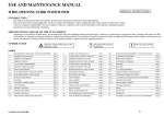
Service manual
hook on fork positioner
Rel.1.3 del 01/01/2010 Pag.1/16
Summary
Page
1.
Introduction
3
2.
Description and functioning
4
3.
Assembling instructions
5
3.1 Mounting hook on ISO plate
5
3.2 Mounting hooks on ISO plate
6
3.3 Hydraulic installation
7
Instructions for use
9
4.1 Checks and suggestions
9
4.2 Driving operations to be avoided
9
4.3 Driving operations not allowed
9
Service and Maintenance
10
5.1 Introduction
10
5.2 Periodic or ordinary maintenance
10
5.3 Extraordinary maintenance
11
6.
Breakings and solutions
15
7.
Disposal
16
4.
5.
Rel.1.3 del 01/01/2010 Pag.2/16
1.Introduction
This Manual includes instructions for: assembling, maintenance (periodic and extraordinary), possible
damages with solution. The instructions in this manual do not substitute but integrate the obligation to
respect the present law regarding the safety and anti- industrial accidents regulation, that are under
responsibility of the User-Company. The User Company is also obliged to point out all instructions present in
this Manual, included the staff’s training for the correct use of the Attachment and for its maintenance.
Forklift Attachment, suitable for the positioning of load forks during pallets-movement that have different
dimensions. It is composed by a bar-chassis with lower ISO Profile. The forks positioning, according to the
pallets openings, must be done before the clamping of the load.
Each Attachment is introduced in the market on pallets which have standard dimension (800x1200 mm) with
two fixing polyester belts end with a thermorestricting cover.
Situation of danger possibility for
safety’s driver
Adhesive labels anti-accident
Adhesive Label
Rel.1.3 del 01/01/2010 Pag.3/16
2.Description and functioning
Device for positioning the load forks (Pic.1) in a synchronized way
Such device is formed by a chassis in the upper side there is a bar used like guide’s and load’s support,
moved by the forks.
The load forks, supplied by us, have in the upper side guide bushings and wiper rings, they are moved by
double effect front cylinders and in the lower side we have sliding rollers with greasers.
The “STANDARD” hydraulic installation has flow divider 50/50 and entrance with metric threaded pipe-fittings
and cutting ring DIN 3861-B diameter 8 mm.
Herebelow the layout of the adhesive label (Pic.2) and the layout of the anti-accidents adhesive label.
(Pic.3).
Load Fork
(Pic.1)
Chassis
Bar
Label
anti-accidents
label
Upper hook
Cylinder
Lower hook
Anchorage
Rollers
(Pic.2)
(Pic.3)
Rel.1.3 del 01/01/2010 Pag.4/16
3. Assembling instruction
3.1 Mounting hooks on ISO plate
-
Unscrew the left hook HL (Pic.4) and the right hook HR (Pic.5)
Lift the fork positioner from point A (Pic.4)
Centre the lock B (Pic.4) on lift truck’s mounting plate C (Pic.5)
Tighten the bolts M14 of the left hook HL and the right hook HR (Pic.4) to 135 Nm (100 Ft-Lbs).
(Pic.4)
A
B
HL
(Pic.5)
HR
C
Attention: Check the exact matching
between hooks and lift truck plate.
C
Rel.1.3 del 01/01/2010 Pag.5/16
3. Assembling instruction
3.2 Mounting hooks on ISO plate
3.2.1 Remove the four bolts with 10 mm spanner (Pic.6 DM1), insert the ISO forks in the support profile
(Pic.6 DM2), tighten again the bolts with the washers (Pic.6 DM1) to a couple of 85 Nm, (63 Ft-Lbs)
3.2.2 Tighten he bolts with 18 mm spanner and the nuts with a 6 mm screw socket (Pic.6 DM3 DM4) until the
bolts will be tighten on the fork.
3.2.3 Tighten the nuts on the bolts (Pic.6 DM3 DM4) to a couple of 50 Nm (37 Ft-Lbs).
(Pic.6)
ATTENTION: Verify that all nuts and
bolts will be tighten correctly.
Rel.1.3 del 01/01/2010 Pag.6/16
3. Assembling instruction
3.3 Forks assembling with ISO rollers hooks
3.3.1.Remove the two bolts wth 5 mm screw (pic.7 DM1), remove the pin diameter 10 (pic.7 DM2), insert the
forks ISO into hook’s profile (Pic.7. DM3), insert the pin diameter 10 (Pic.7 DM2), tighten again the bolts (Pic.
7 DM1) to a couple of 42 Nm, (31 Ft-Lbs)
3.3.2 Tighten the bolts with screw of 18 mm and the nuts with special spanner of 6 mm (Pic.7 DM4 DM5) till
the fork is bolted.
3.3.3 Tighten the nuts on the bolts (Pic.7 DM4 DM5) to a couple of 50 Nm (37 Ft-Lbs)
(Pic.7)
ATTENTION: Verify that all nuts and
bolts will be tighten correctly.
Rel.1.3 del 01/01/2010 Pag.7/16
3.Assembling Instruction
3.4 Hydraulic Installation
3.4.1 Connect, with flexible tubes complete with terminal pipe-fittings diameter 8 with nut 14x1.5 mm, the
installation located on the Lift-Truck’s mast to the pipe-fittings:
“open” for opening
“close” for closing”
“SL” for left sideshifting
“SR” for right sideshifting
As indicated in picture n.6/6a, tightening the nuts with couple of 60 Nm (43 Ft-Lbs).
3.4.2 Do some testing movements in order to verify the perfect hydraulic keeping of pipe-fittings, the speed
and the synchronism of forks movement. In case of oil’s leaks demount the involved fittings and clean it
carefully. Forks speed and synchronism are checked automatically by a flow divider put on the aluminium
valve.
(Pic.8)
(Pic.9)
Front view of Hydraulic Installation
References left – right Lift Truck’s driver’s side
Attention: Connect the pipes as per
attached hydraulic scheme.
Attention: Do some testing movement
before starting.
Rel.1.3 del 01/01/2010 Pag.8/16
4.Instructions for use
4.1 Checks and suggestions
-
Fork the load in the most possible central position
Keep the load in a few lifted position in order to have a bigger Lift Truck’s stability during the movements.
Keep the load with lifted fork’s tips during the lift truck’s movement.
Move the control levers in a soft way in order to avoid sudden pressure changes in the hydraulic
installation and consequently compromise the load stability.
- Adapt the Lift truck’s speed according to the type of load and according to the difficulties about space
- Pay attention to the floor’s steep, or to its inclination as both situation can affect the load’s stability.
- Before moving the pallet adjust the fork’s position in order not to force them against the base of the pallet.
4.2 Movements to be avoided (D-E-F-G Pic.10)
-
To move bigger loads than the nominal capacity.
To move not stable loads
To move the load with only one fork, even if the weight is not so much.
To move a side load using the load which is already on the forks.
To effect very quickly movements of lift truck with the load on forks in high position
To effect sideshifting stroke or forks positioning with the load on forks e lift truck on movement.
4.3 Movements not allowed
-
To use the attachment for different purposes than those ones for which it has been built.
To move the movements control lever when the attachment is under maintenance
To drive the lift truck during bad visibility conditions due to a too big load
To tamper with the attachment.
To stop in the action area of the attachment. (Pic.11)
To use the attachment when it presents a deformation, even minimal, of its structure or in any case
problem in its functioning.
- It is not a clamp (do not use the forks to block the load either in opening or in closing (Pic.10 D-E-FG)
(Pic.10)
(Pic.11)
Danger Area
Rel.1.3 del 01/01/2010 Pag.9/16
5.Maintenance
5.1 Introduction
The attachment is delivered with the guides greased with high quality grease in order to warranty normal
adjustment and polishing of the rubbing surfaces during the first period of using.
The recommended grease is ISO X M2 (SHELL ALVANIA GREASE R2 or correspondent type)
Using the attachment in very dusty environment, we suggest to use the oil ISO CB 32 (ESSO NUTO 32 or
correspondent type)
The below indicated maintenance is connected to a correct use of the attachment in a clean and very few
dusty environment.
5.2 Periodic or ordinary maintenance
5.2.1 Maintenance every 500 hours
- Grease in area “g.1” (Pic.13) e (Pic.14).
- Checking screws’ tightening in points “s.1”, in case of screws’ working loose, for Types ISO 2 e ISO 3
35 Tons tighten them with couple 89 Nm (65 Ft-Lbs) and for types ISO3 49 Q.li with couple 135 Nm (100
Ft-Lbs) for types ISO 3 49 q.li;
In case of substitution or demounting of the above mentioned screws mount them again with the
relative washers in the appropriate way, as showed in the picture and on adhesive label on
attachment.
Attention: After 5 re-utilizations the washers NORD-LOCK (Pic.12) have to be changed with new
ones.
- Check the screw tightening of the chromium-plate bar’s lock. Point “s.2” (in case of screw’s working
loose, clean the screw and tighten it again using “Loctite 243”.
- Check hydraulic fittings
- Check general condition of the attachment
5.2.2 Maintenance every 1000 hours :
(Pic.12)
In addition to what as been indicated in point 5.2.1 do:
- Cleaning of roller’s slide guides
- Check of general condition of the attachment
- Specific checking of pipes condition
(Pic.13)
g.1
(Pic.14)
s.1
g.1
g.1
s.2
g.1
g.1
g.1
s.1
Rel.1.3 del 01/01/2010 Pag.10/16
5.Maintenance
5.3 Extraordinary maintenance
Introduction operation
- Before starting any special maintenance, switch off the Lift Truck and take off the pressure in the
supply circuit.
- Be sure that during all maintenance period the pump has not to be put on function and the lever’s
distributor has not to be put in action.
5.3.1 Cylinder demounting and fork’s moving (for attachments with capacity 2,5 e 3,5 t) (Pic.15)
- Take off the elastic ring pos. “sm1” using a screwdriver
- Take out the pin pos. “sm2” with punch diam. 8 mm
- Unscrew the two bolts pos. “sm3”
(Pic.15)
Sm.2
Sm.1
Sm.3
Rel.1.3 del 01/01/2010 Pag.11/16
5.Maintenance
5.3.2 Substitution of cylinder’s seals (Pic.16)
- Unscrew the plug “cs05”, with the appropriate tool, and take it out from the rod
- Take out the rod “cs02” from cylinder’s case
- Proceed with the seals’ substitution “cs01”, “cs03”, “cs04”, “cs06”, “cs07” e “re03” (wherever is necessary
use screwdriver)
The cylinder’s remounting must be done in the opposite way than the above described one, using particular
attention to the cleaning and checking the exact position of the seals “cs06” e “cs07” (Dett.cp)
(Pic.16)
Rel.1.3 del 01/01/2010 Pag.12/16
5.Maintenance
5.3.3 Scheme of Hydraulic Installation (Pic.17/18)
(Pic.17)
(Pic.18)
Front View of Hydraulic Installation
Please refer left-right driver’s side of the Lift Truck
NB: The Lift-Truck Manufacturer will give instruction about the distributor to use.
NB: For eventual breaking concerning the Fork Positioner, please check point 6 “BREAKINGS AND
SOLUTIONS ” of this Manual.
Rel.1.3 del 01/01/2010 Pag.13/16
5.Maintenance
5.3.4 Substitution of Seal’s Valve (Pic.19/20)
-
gv.1
Unscrew the flow divider “gv1” (Fig.19/20)
Unscrew the cartridge “gv2” (Fig.19)
Unscrew the cartridge “gv3” (Fig.19)
Proceed with the seals’ substitution “g1”, “g2”, “g3” (Fig.19/20)
Remount the cartridges tighten 45 Nm (33 Ft-Lbs) (Fig.19)
Remount the flow divider tighten a 60 Nm (44 Ft-Lbs) (Fig.19/20)
gv.2
(Pic.19)
G1
G2
(Pic.20)
gv.1
G1
G3
gv.3
Rel.1.3 del 01/01/2010 Pag.14/16
6.Breakings and solution
Breakings
6.1 there is no fork’s movement
6.2 Forks’ movement is too low
6.3 There is no synchronised
movement of the forks
Reasons
Obstacles or too much amassed
dirty on slide-bars
Not enough hydraulic pressure
Obstruction or breakings in the
hydraulic installation
Internal cylinder’s leaking (wear
and tear seals )
Not enough oil’s capacity
Obstructions in the Hydraulic
Installation
Internal Cylinder’s leaking (wear
and tear seals )
Obstacles or too much amassed
dirty on slide –bars
Seals wear and tear on flow
divider
Solution
Remove the obstacles , clean and
grease the slide-bars
Checking and adjustement of the
supplied pressure of the Lift Truck
pump.
Eliminate the obstruction or
substitute the damaged pipe
Checking and eventual substitution
of the seals check point “5.3.2”
Checking and adjustement of the
supplied capacity by the lift truck
pump.
Eliminate the obstruction or
substitution of the damaged tube
Checking and eventual substitution of
the seals–check point “5.3.2”
Remove the obstacles, clean and
grease the slide-bars
Checking and eventual substitution of
the seals see point “5.3.4”
Note: Whenever there are difficulties concerning a correct intervention, or the defect is different or missing
from those ones described above, we please you to contact the technical service assistance.
Rel.1.3 del 01/01/2010 Pag.15/16
7.Disposal
If we want to get rid f the attachment we suggest to divide and collect separately all recycle materials.
Parts
Chassis, cylinders and forks
Lower hooks
Pads
Paint
Fixing belts
Bushings
Hydraulic oil
Pallet
Housing
Cylinder seals
Materials
Steel
Cast Iron
Nylon / bronze
Paint
Polyester
Bronze
According to local laws
Wood
Polyester / Steel
Poliuretan and NBR
Attention: not recycle Materials or in any case those ones that may be a danger for
the environment (Oil, Gum, Plastic, etc) must be disposal according to the local
directives
Rel.1.3 del 01/01/2010 Pag.16/16