1
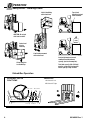
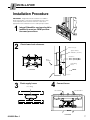
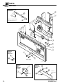
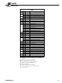
U
SER MANUAL
C-Series
Integral Sideshifter
Manual Number 6014809 R-1
姞
cascade
Cascade is a Registered Trademark of Cascade Corporation
C
ONTENTS
Page
INTRODUCTION
Special Definitions
OPERATION
Safety Rules
Industrial Lift Trucks
Handling Loads
Integral Sideshifter Operation
Safe Operation and Maintenance
OSHA Regulations
INSTALLATION
Truck Requirements
Recommended Hydraulic Supply
Installation Procedure
INSPECTION & MAINTENANCE
Daily
100-Hour Maintenance
300-Hour Maintenance
1000-Hour Maintenance
PARTS
Product Identification
Base Unit
Cylinder Assembly, Backrest
Recommended Spares, Publications
2
3
3
4
4
5
5
6
6
7
9
9
9
9
9
10
12
13
I
NTRODUCTION
This User Manual is for Cascade Integral Sideshifters.
It contains an Operation Guide, Installation Instructions, and
Parts Manual. All specifications are shown in U.S. and
(Metric) units where applicable.
IMPORTANT: Cylinder ports are #6 SAE O-Ring
(.5625 in. dia., 18UNF-2B)
Special Definitions
The statements shown appear throughout this Manual
where special emphasis is required. Read all WARNINGS
and CAUTIONS before proceeding with any work.
Statements labeled IMPORTANT and NOTE are provided
as additional information of special significance or to
make the job easier.
WARNING: Rated capacity of the truck/
attachment combination is a responsibility
of the original truck manufacturer and may
be less than shown on the attachment
nameplate. Consult the truck nameplate.
WARNING: Do not operate this attachment
unless you are a trained and authorized lift
truck driver.
WARNING – A statement preceded by
WARNING is information that should be
acted upon to prevent bodily injury. A
WARNING is always inside a ruled box.
CAUTION – A statement preceded by CAUTION is
information that should be acted upon to prevent
machine damage.
IMPORTANT – A statement preceded by IMPORTANT is
information that possesses special significance.
NOTE – A statement preceded by NOTE is information
that is handy to know and may make the job easier.
O
PERATION
This Section contains operating instructions for Cascade
Integral Sideshifters. It will help you avoid common errors
which often cause damage to the equipment or product
being handled.
Backrest
This information is intended to simplify operator understanding about effective and safe Sideshifter use and
operation. Read this information thoroughly before
operating the Attachment. Be sure you know and
understand all operating procedures and safety precautions. If you have any questions, or don’t understand a
procedure, ask your supervisor.
Cylinder
Emphasize Safety! Most accidents are caused by
operator carelessness or misjudgement. You must
watch for poorly maintained equipment and
hazardous situations and correct them.
Carriage
Sideshifter
Frame
SS0380.ill
Forks
2
6014809 Rev. 1
O
PERATION
Safety Rules – Industrial Lift Trucks
No riders
No reaching through mast
No standing under load
GA0047.ill
Tilt
Raise
With load
3 in.
(8 cm)
No load
P
P
Traveling
empty
Motor off, park, lower load
RAMPS
P
No parking on ramp
No turning on ramp
Watch clearances
GA0048.ill
STOP
Observe
Wet floors
6014809 Rev. 1
Workers
Stops
Bumps
Dips
Slow for
two-way traffic
Sound horn, slow
at intersection
Sound horn, slow
at corner
3
O
PERATION
Safety Rules – Handling Loads
Top of load
should not extend
above backrest.
Limit sideshifting
with raised load.
CAUTION: Do not put
side loads on forks.
LOAD
WEIGHT
Center load
prior to
traveling.
Limit truck movement
with raised load.
FP0017.ill
Load weight must not exceed
combined truck/attachment
capacity (see truck nameplate).
Raise load prior
to sideshifting.
Total fork capacity (LH + RH fork)
must be greater than load weight.
Check capacity stamp on forks.
Sideshifter Operation
AUXILIARY VALVE
FUNCTIONS
SIDESHIFTING
A Sideshift Left
B Sideshift Right
Hoist down
Tilt forward
A
B
A
B
SS0367.ill
GA0010.ill
4
Hoist up Tilt Back
6014809 Rev. 1
S
AFE OPERATION AND MAINTENANCE
OSHA Regulations – Industrial Trucks and Attachments (Specific Regulations from OSHA 1910.178)
WARNING: The safe operation and maintenance of
industrial trucks is regulated by Occupational Safety
and Health (OSHA) regulations 1910.178 and American National Standards Institute (ANSI) Safety Standard for
Powered Industrial Trucks, ANSI B56.1. When operating and
maintaining industrial trucks equipped with attachments you
should pay particular attention to the following sections of these
regulations. You should be familiar with all sections of these
regulations. Ask your employer for the complete regulations.
(a) General Requirement
(4) Modifications and additions which affect capacity and safe
operation shall not be performed by the customer or user without
manufacturers prior written approval. Capacity, operation and
maintenance instruction plates, tags or decals shall be changed
accordingly.
(5) If the truck is equipped with front-end attachments other than
factory installed attachments, the user shall request that the
truck be marked to identify the attachments and show the
appropriate weight of the truck and attachment combination at
maximum elevation with load laterally centered.
(6) The user shall see that all nameplates and markings are in place
and maintained in a legible condition.
(e) Safety Guards
(2) If the type of load presents a hazard, the user shall equip fork
trucks with a vertical load backrest extension in accordance with
(a)(2) following.
(a)(2) All new powered industrial trucks acquired and used by
an employer after February 15, 1972 shall meet the design and
construction requirements for powered industrial trucks
established in the “American National Standard for Powered
Industrial Trucks, Part II, ANSI B56.1”, except for vehicles
intended primarily for earth moving or over-the-road hauling.
(l) Operator Training
Only trained and authorized operators shall be permitted to operate
a powered industrial truck. Methods shall be devised to train
operators in the safe operation of powered industrial trucks.
(m) Truck Operations
(1) Trucks shall not be driven up to anyone standing in front of a
bench or other fixed object.
(2) No person shall be allowed to stand or pass under the elevated
portion of any truck, whether loaded or empty.
(3) Unauthorized personnel shall not be permitted to ride on
powered industrial trucks. A safe place to ride shall be provided
where riding of trucks is authorized.
(4) The employer shall prohibit arms or legs from being placed
between the uprights of the mast or outside the running lines of
the truck.
(5i) When a powered industrial truck is left unattended, load
engaging means shall be fully lowered, controls shall be
neutralized, power shall be shut off and brakes set. Wheels shall
be blocked if the truck is parked on an incline.
(5ii) A powered industrial truck is unattended when the operator is 25
feet or more away from the vehicle which remains in his view, or
whenever the operator leaves the vehicle and it is not in his view.
(5iii) When the operator of an industrial truck is dismounted and
within 25 feet of the truck still in his view, the load engaging
means shall be fully lowered, controls neutralized and the
brakes set to prevent movement.
6014809 Rev. 1
(6) A safe distance shall be maintained from the edge of ramps or
platforms while on any elevated dock or platform or freight car.
Trucks shall not be used for opening or closing freight doors.
(10) A load backrest extension shall be used whenever necessary to
minimize the possibility of the load or part of it from falling
rearward.
(n) Traveling
(4) The driver shall be required to slow down and sound the horn at
cross isles and other locations where vision is obstructed. If the
load being carried obstructs forward view, the driver shall be
required to travel with the load trailing.
(7i) When ascending or descending grades in excess of 10 percent,
loaded trucks shall be driven with the load upgrade.
(7iii) On all grades the load and load engaging means shall be tilted
back if applicable, and raised only as far as necessary to clear
the road surface.
(o) Loading
(1) Only stable or safely arranged loads shall be handled. Caution
shall be exercised when handling off-center loads which cannot
be centered.
(2) Only loads within the rated capacity of the truck shall be handled.
(3) The long or high (including multiple-tiered) loads which may
affect capacity shall be adjusted.
(4) Trucks equipped with attachments shall be operated as partially
loaded trucks when not handling a load.
(5) A load engaging means shall be placed under the load as far as
possible; the mast shall be carefully tilted backward to stabilize
the load.
(6) Extreme care shall be used when tilting the load forward or
backward, particularly when high tiering. Tilting forward with load
engaging means elevated shall be prohibited except to pick up
a load. An elevated load shall not be tilted forward except when
the load is in a deposit position over a rack or stack. When
stacking or tiering, only enough backward tilt to stabilize the load
shall be used.
(p) Operation of the Truck
(1) If at any time a powered industrial truck is found to be in need of
repair, defective, or in any way unsafe, the truck shall be taken out
of service until it has been restored to safe operating condition.
(q) Maintenance of Industrial Trucks
(1) Any power-operated industrial truck not in safe operating
condition shall be removed from service. All repairs shall be
made by authorized personnel.
(5) All parts of any such industrial truck requiring replacement shall
be replaced only by parts equivalent as to safety with those used
in the original design.
(6) Industrial trucks shall not be altered so that the relative positions
of the various parts are different from what they were when
originally received from the manufacturer, nor shall they be altered
either by the addition of extra parts not provided by the manufacturer or by the elimination of any parts. Additional counterweighting of fork trucks shall not be done unless approved by
the truck manufacturer.
(7) Industrial trucks shall be examined before being placed in service
and shall not be placed in service if the examination shows any
condition adversely affecting the safety of the vehicle. Such
examinations shall be made at least daily. When industrial trucks
are used on a round-the-clock basis, they shall be examined after
each shift. Defects when found shall be immediately reported
and corrected.
5
I
NSTALLATION
Truck Requirements
Truck Relief Setting
2000 psi (140 bar) Recommended
3500 psi (240 bar) Maximum
Truck Flow Volume ➀
55C
Min. ➁
Recommended
Max. ➂
1 GPM
(4 L/min.)
2 GPM
(7.5 L/min.)
3 GPM
(12 L/min.)
➀ Cascade Integral Sideshifters are compatible with SAE 10W
petroleum base hydraulic fluid meeting Mil. Spec. MIL-0-5606 or
MIL-0-2104B. Use of synthetic or aqueous base hydraulic fluid
is not recommended. If fire resistant hydraulic fluid is
required, special seals may be required. Contact Cascade.
➁ Flow less than recommended will result in slow sideshift speed.
➂ Flow greater than maximum can result in excessive heating,
reduced system performance and reduced hydraulic system life.
GA0158.ill
Auxiliary Valve Functions
Check for compliance with
ITA (ISO) standards:
Tilt
Forward
Hoist Down
Sideshift
Left
Recommended
Hydraulic Supply
The Integral Sideshifter requires the hydraulic supply arrangement shown below. All hoses and fittings should be at
least No. 6 with 9/32 in. (7 mm) minimum I.D.
GA0094.ill
Hoist Up Tilt
Sideshift
Back Right
A Mast Single Internal Hose Reeving
A
GA0157.ill
6
6014809 Rev. 1
I
NSTALLATION
Installation Procedure
IMPORTANT: Integral Attachment installation is an OEM or
dealer responsiblity. Some of the following Steps may or may
not be required, but are shown for reference. Refer to the
appropriate Service Manual for service and repair procedures.
1
Integral Sideshifter carriage should be
installed in mast per OEM specifications and procedures.
SS0387.ill
2
Check lower hook clearance
Lower Hook (2)
Tighten bolts to
120 ft.-lbs. (165 Nm).
Clearance:
1/32 in. (0.8 mm) Min.
1/16 in. (1.6 mm) Max.
Mast
Carriage
Sideshifting
Frame
Front View
FRONT
SS0365.ill
3
4
Flush supply hoses
Union Fitting
Connect hoses
Sideshift RIGHT
Sideshift LEFT
GA0171.ill
Front View
6014809 Rev. 1
7
I
NSTALLATION
5
Install forks
Use blocks as necessary to raise forks to
installation height. Keep feet clear of forks
when installing.
SS0388.ill
7
Check Sideshifter bearing lubrication
6
Install backrest
Cascade Backrest –
Tighten to 145 ft.-lbs.
(195 Nm). For other
backrests, see OEM
recommendations.
SS0389.ill
Upper bearing grease fittings
Bearings are prelubed at the Factory with
break-in grease. No additional lubrication
is required during installation.
NOTE: After 300 hours of operation,
sideshifter bearings should be lubricated
with general-purpose lithium-based chassis
grease.
SS0382.ill
Lower bearing grease areas
Front View
8
6014809 Rev. 1
I
NSPECTION & MAINTENANCE
Backrest
WARNING: After completing any service
procedure, always test the Integral Sideshifter
through five complete cycles. First test with
no load, then test with a load to make sure the Sideshifter
operates correctly before returning it to the job.
Cylinder
and hoses
Daily
Fork
Stops
Check items shown each day. Report problems to your
supervisor. See Service Manual for troubleshooting,
maintenance and repair procedures. NOTE: Carriage
should be maintained per OEM service specifications.
100-Hour
Every time the lift truck is serviced or every 100 hours
of truck operation, whichever comes first, complete
the following maintenance procedures:
Forks
• Check for loose or missing bolts, worn or damaged
hoses, hydraulic leaks, and damaged or missing fork
stops.
• Inspect lower hooks for wear and proper clearance.
Adjust if necessary (see Step 2, Installation). Tighten
lower hook capscrews to 120 ft.-lbs (165 Nm).
300-Hour
After each 300 hours of truck operation, in addition to the
100-hour maintenance, perform the following procedures:
• Tighten Cascade backrest capscrews to
145 ft.-lbs. (195 Nm).
• Lubricate Sideshifter upper and lower bearings with
general-purpose lithium-based chassis grease.
P
SS0386.ill
Lower
Hooks
Fasteners
1000-Hour
After each 1000 hours of truck operation, in addition to the
100 and 300-hour maintenance, perform the following
procedures:
• Inspect upper and lower bearings for wear. If any
bearing is worn to less than 3/32 in. (2.5 mm) thickness,
replace the entire bearing set (see Service Manual).
• Inspect forks (if equipped) for wear. NOTE: Fork Safety
Kit 3014162 is available containing wear calipers,
inspection sheets and safety poster. Also available are
fork hook & carriage wear gauges 209560 (CL II), and
209561 (CL III).
ARTS
Product Identification – This Section shows replacement
parts for Integral Sideshifters. The product model number
and serial number are stamped on the inside surface of the
RH vertical sideplate (driver's view), and must be provided
when ordering replacement parts. The cylinder assembly
part number is stamped on the LH topside (driver's view).
Stamped model number,
serial number, specifications.
WARNING: For the safety of yourself and
others, DO NOT install the parts shown in
this Manual unless you have thoroughly
reviewed the appropriate Service Manual.
Sticker showing patent numbers,
phone numbers for service.
Stamped
cylinder
assembly
part number
(LH topside).
Stamped frame
part number
SS0361.ill
Back (Driver's) View
6014809 Rev. 1
9
P
ARTS
Base Unit
Optional Solid Link
Kit 6020173
2
‡
#
@
1
SS0420.ill
Replaces cylinder if using
sideshifting attachment.
$
5
&
^
4
0
@
#
8
%
9
$
3
6
^
&
!
Optional
Center
Capscrew
⁄
¤
7
Front View
SS0423.ill
SS0418.ill
*
Optional
Pallet
Guard Kit
6018250
(
SS0422.ill
Optional
Hydraulics
Guard
fi
fl
‹
Stamped
Part Number
›
)
SS0421.ill
10
6014809 Rev. 1
P
ARTS
Base Unit
55C
REF QTY
1
2
3
4
5
★6
★7
8
9
10
★11
◆12
◆13
◆14
15
16
17
▲18
▲19
▲20
21
22
23
24
25
26
◆27
1
2
2
2
2
1
1
2
4
2
2
2
2
2
2
2
2
1
4
2
2
▼
2
2
2
2
1
1
2
2
1
1
1
1
4
4
4
4
1
PART NO.
●
8508374
8509289
8508376
8509290
✖
■
8508373
667225
7403
601676
207304
667222
666984
604511
211807
220832
769050
684295
6016592
6016912
6016591
221733
206488
209648
221906
219400
6018251
768557
683822
768825
678991
◗
◗
4057
643511
6229
228818
6020156
DESCRIPTION
Inner Carriage Weldment
Upper Bearing, Composite
Upper Bearing, Bronze (optional)
Lower Bearing, Composite
Lower Bearing, Bronze (optional)
Frame Weldment
Cylinder Assembly
Lower Hook
Washer-HD, M16
Grease Fitting
Fitting–90, 6-6
Fitting–90, Long, 6-6
Fitting–90, 5-6
Fitting–90, 4-6
Fitting–STR, 6-6
Fitting–90, Face Seal, 4-6
Fitting–STR, Face Seal, 4-6
Roll Pin
Capscrew, M16 x 2
Clevis Pin
Hairpin Cotter
Shim, Cylinder
Flow Restrictor, 1.5 mm
Flow Restrictor, 1.32 mm
Flow Restrictor, 1.27 mm
Safety Decal
Fork Stop Kit (includes 2 stops)
Pallet Guard
Capscrew, M12 x 1.75
Lockwasher, M12
Center Capscrew, M12 x 1.75
Lockwasher, High Collar, M12
Hydraulic Guard, Solid (optional)
Hydraulic Guard, Mesh (optional)
Capscrew, FH, (Solid Guard)
Capscrew, Hex (Mesh Guard)
Washer
Jam Nut
Solid Link (optional)
● If Carriage needs replacing, order complete Sideshifter
Assembly.
✖ Order part number stamped on frame.
■ See Cylinder page for parts breakdown.
★ Included in Lower Hook Service Kit 6018267.
◆ Included in Solid Link Kit 6020173.
▼ Quantity as required.
▲ Included in Pallet Guard Kit 6018250.
◗ Order part number stamped on Hydraulic Guard.
Reference: SK-7069
6014809 Rev. 1
11
P
ARTS
Cylinder Assembly, Backrest
1 2
3 4
SS0368.ill
7 6
Front View
5
55C
REF QTY
1
●2
●3
●4
●5
6
7
●
◆
●
✖
■
★
▼
1
2
2
2
2
—
—
2
2
▼
PART NO.
◆
562132
415866
562131
6017490
■
■
6016592
6016912
6016591
DESCRIPTION
Cylinder Assembly
Rod Seal ✖
O-Ring, 70 Duro ✖
Rod Wiper Seal ✖
Retainer/Seal Carrier Assembly
Rod/Piston Assembly
Cylinder Shell
Clevis Pin ★
Hairpin Cotter ★
Shim, Cylinder ★
Stamped
Cylinder Assembly
Part Number
SS0383.ill
Front View
Refer to part number stamped on cylinder top.
Included in Rod Seal Service Kit 6019928.
Preloaded in Retainer/Seal Carrier Assembly 6017490.
Not serviceable, order new Cylinder Assembly.
Not shown, see Base Unit page for illustration.
Quantity as required.
1
55C
Backrest Height
REF QTY
1
1
1
1
1
2
3
1
1
1
1
1
4
4
36 in.
(91.5 cm)
48 in.
60 in.
(122 cm) (152.5 cm)
PART NO.
PART NO.
PART NO.
684769
684772
684775
684778
684781
684770
684773
684776
684779
684782
200173
684586
684771
684774
684777
684780
684783
3
2
DESCRIPTION
Backrest – 31 in. (78.7 cm) Width
Backrest – 37 in. (94 cm) Width
Backrest – 41 in. (104 cm) Width
Backrest – 49 in. (124.5 cm) Width
Backrest – 61 in. (155 cm) Width
Capscrew, M16x2 x 35
Lockwasher, M16
SS0198.ill
Reference: S-3370
12
6014809 Rev. 1
P
ARTS
Recommended Spare Parts, Publications
55C
PART NUMBER
UNITS SERVICED
DESCRIPTION
1-5
6-19
20-50
8508374
8508376
8508373
684295
667225
BASE UNIT AND MOUNTING
Upper Bearing, Composite
Lower Bearing, Composite
Lower Hook
Capscrew, M16 x 2
Washer, HD, M16
8
6
0
0
0
16
12
2
4
4
32
24
4
8
8
6020048
6019928
CYLINDER
Cylinder Assembly
Rod Seal Service Kit
0
1
0
2
1
4
Integral Sideshifter
cascade
L
䊛
LS
T
OO
S
ERV
ICE
MAN
UA
Service Literature Index
and Order Form
Ordering Information Parts, Service and Operator Guide literature is sold through the Cascade Parts Depot.
All dealerships with an open account, please indicate quantity desired and purchase order number. All others
please enclose a check payable to Cascade Corporation.
FAX:
513-325-9270
Master Service Manual
Mail:
Phone:
Cascade Corporation
P.O. Box 360
Springfield, Ohio 45501
513-322-1199
Part No. 673969
Includes all Service manuals listed in a 3-ring binder for $140.00.
U
PART NO.
6014809
6020275
679929
673964
DESCRIPTION
User Manual (Operation, Installation, Parts)
Service Manual
Tool Catalog
Literature Index Order Form
SER MANUAL
cascade姞
Cascade is a Registered Trademark of Cascade Corporation
GA0098.ill
6014809 Rev. 1
13
Contacting Cascade
Users – Cascade product literature, service literature, parts and videos are available through authorized lift truck
dealers. To find the dealer nearest you, contact:
North America/South America
Cascade Corporation
U.S. Headquarters
2201 NE 201st
Fairview, OR 97024-9718
Tel: 800-CASCADE (227-2233)
503-669-6300
Fax: 888-329-8207
Europe
Cascade N.V.
European Headquarters
P.O. Box 3009
1300 El Almere
Damsluisweg 56
1332 ED Almere
The Netherlands
Tel: 31-36-5492911
Fax: 31-36-5492964
Lift Truck Dealers – To order parts, service literature or videos:
North America/South America
Cascade Parts Sales
2501 Sheridan Ave.
Springfield, OH 45505
Tel: 888-CASCADE (227-2233)
Fax: 888-329-0234
c
© Cascade Corporation 2001
12-2001
Part Number 6014809 R-1