1
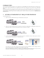
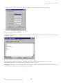
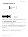
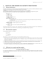
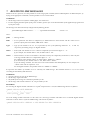
3URWRFROORPRGHP*60SHUS&2*60PRGHPSURWRFROIRUS&2
Manuale d’uso
User manual
Vogliamo farvi risparmiare tempo e denaro!
Vi assicuriamo che la completa lettura di questo manuale vi garantirà una
corretta installazione ed un sicuro utilizzo del prodotto descritto.
We wish to save you time and money!
We can assure you that the thorough reading of this manual will guarantee
correct installation and safe use of the product described
INDICE
AVVERTENZE IMPORTANTI...................................................................................................................................... 1
INTRODUZIONE............................................................................................................................................................. 3
1.
GENERALITÀ SUL PROTOCOLLO pCO2/GSM ............................................................................................ 3
2.
REQUISITI PER L’UTILIZZO DEL PROTOCOLLO ..................................................................................... 4
2.1 REQUISITI DEL PCO2 .............................................................................................................................................. 4
2.2 REQUISITI DEL MODEM GSM................................................................................................................................. 4
2.2.1
Disabilitazione del controllo di flusso del modem ........................................................................................ 4
2.2.2
Disabilitazione del codice PIN ...................................................................................................................... 7
2.2.3
Inserimento del numero del Centro Servizi ................................................................................................... 7
2.2.4
Cancellazione di tutti i messaggi prima dell’impiego.................................................................................... 7
3.
SELEZIONE DEL PROTOCOLLO pCO2/GSM............................................................................................... 8
4.
CONNESSIONI...................................................................................................................................................... 8
4.1 SCHEDA SERIALE RS232 ....................................................................................................................................... 8
4.1.1
Selezione del baudrate di comunicazione tra pCO² e modem ....................................................................... 8
4.1.2
Il problema dell’auto-baudrate nel SIEMENS T35 ....................................................................................... 8
4.2 CAVO PCO2 - MODEM............................................................................................................................................ 8
5.
CENNI SULLE PROCEDURE DI GESTIONE DEL MODEM ....................................................................... 9
5.1 INIZIALIZZAZIONE DEL MODEM .............................................................................................................................. 9
5.2 SEQUENZA DI DISCONNESSIONE ............................................................................................................................. 9
5.3 NUMERO VOCE E NUMERO DATI DI UNA SIM CARD .................................................................................................... 9
6.
INVIO DI MESSAGGI SMS DI ALLARME .................................................................................................... 10
6.1
6.2
7.
ESITO DELLA SPEDIZIONE DEL MESSAGGIO .......................................................................................................... 10
SET DI CARATTERI ............................................................................................................................................... 10
RICEZIONE DI MESSAGGI SMS .................................................................................................................... 11
7.1
ESITO DELLA RICEZIONE DEL MESSAGGIO ............................................................................................................ 12
Protocollo modem GSM per pCO 2
AVVERTENZE IMPORTANTI
PRIMA DI INSTALLARE O INTERVENIRE SULL’APPARECCHIO, LEGGERE ATTENTAMENTE E SEGUIRE
LE ISTRUZIONI CONTENUTE IN QUESTO MANUALE.
Questa apparecchiatura è stata costruita per funzionare senza rischi per gli scopi prefissati purché:
• l’installazione, la conduzione e la manutenzione siano eseguite secondo le istruzioni contenute in questo manuale;
• le condizioni dell’ambiente e della tensione di alimentazione rientrino tra quelle specificate.
Ogni utilizzo diverso da questo e l’apporto di modifiche, non espressamente autorizzate dal costruttore, sono da
intendersi impropri.
La responsabilità di lesioni o danni causati da uso improprio ricadrà esclusivamente sull’utilizzatore.
Si osservi che questa macchina contiene componenti elettrici sotto tensione e quindi tutte le operazioni di servizio o
manutenzione devono essere condotte da personale esperto e qualificato, cosciente delle necessarie precauzioni.
Prima di accedere alle parti interne sezionare la macchina dalla rete elettrica.
Smaltimento delle parti del controllore
Il controllore è composto da parti in metallo e da parti in plastica. Tutte queste parti vanno smaltite secondo le
Normative locali in materia di smaltimento.
Omologazioni: la qualità e la sicurezza dei prodotti Carel sono garantite dal sistema di progettazione e produzione certificato
ISO 9001, nonché dal marchio
.
Cod. Carel +030220330 rel. 2.0 del 30/10/02
1
Protocollo modem GSM per pCO 2
INTRODUZIONE
I controllori programmabili pCO2 Carel sono ora in grado di gestire il nuovo protocollo pCO2/GSM che consente loro,
utilizzando modem GSM, l’invio e la ricezione di messaggi SMS per la segnalazione di allarmi attivi e per il loro eventuale
reset via telefono GSM.
Diventa inoltre possibile collegare un pCO2 ad un supervisore remoto anche quando non si ha a disposizione una linea
telefonica tradizionale. Restano infatti valide tutte le proprietà del protocollo pCO2/Modem che consente l’interfacciamento via
modem delle periferiche pCO2 con un supervisore remoto comunicante con protocollo standard Carel, senza l’ausilio di un
gateway (vedi manuale Protocollo MODEM per pCO2).
GENERALITÀ SUL PROTOCOLLO pCO2/GSM
1.
Il protocollo pCO2/GSM:
1.
consente l’invio da parte del pCO2 di messaggi SMS di allarme via modem GSM,
SMS
2.
consente la ricezione da parte del pCO2 di messaggi SMS inviati esclusivamente da telefono cellulare (l’invio di SMS
tramite Internet non è consentito) per il reset degli allarmi e più in generale per l’impostazione diretta delle variabili,
SMS
3.
come avviene con il protocollo pCO2/Modem, consente al pCO2 di comunicare con un supervisore remoto a cui può
essere indifferentemente collegato un modem GSM o un modem tradizionale.
Dati
oppure
Il significato dei dati scambiati col supervisore e la possibilità di essere letti o modificati dal supervisore stesso
dipende poi dal programma applicativo utilizzato dal pCO2.
Il protocollo implementato nel pCO2 è un sottoinsieme del protocollo standard Carel punto-punto, utilizzato per i
collegamenti locali; non sono disponibili i comandi per il trasferimento dei dati storici, di file e grafici.
Cod. Carel +030220330 rel. 2.0 del 30/10/02
3
Protocollo modem GSM per pCO 2
2.
REQUISITI PER L’UTILIZZO DEL PROTOCOLLO
Per poter collegare il pCO2 ad un modem GSM devono essere soddisfatti i seguenti requisiti.
2.1
1.
2.
3.
2.2
Requisiti del pCO2
L’applicativo deve essere predisposto per la gestione del modem GSM.
Il firmware (BIOS) deve avere versione 2.29 o successiva per i modem dichiarati compatibili riportati nella tabella del
paragrafo successivo, ad esclusione del modem SIEMENS TC35. Nel caso si usi quest’ultimo modem il BIOS deve avere
versione 3.08 o successive.
L’ultima versione è disponibile nell’area Carel TopUser, incluso nel pacchetto EasyTools.
Deve montare la scheda di espansione RS232, codice Carel PCO200MDM0 (vedi Connessioni).
Requisiti del modem GSM
Non tutti i modem GSM sono compatibili con il protocollo PRGHP *60 SHU S&2 . Una indagine su modem di diverse marche
ha dato i seguenti risultati:
TIPO
GSM360
POCKET GSM
GSM 2702-D
WMOD2B*
FALCOM A2D*
FALCOM A3D1
M20
TC35*
MODEM
COSTRUTTORE
TELITAL
DIGICOM
MICROTEL
WAVECOM
FALCOM
FALCOM
SIEMENS
SIEMENS
COMPATIBILITA’
NO
SI
SI
SI
TESTATO
SI
TESTATO
SI
SI
SI
TESTATO
La dicitura TESTATO stà a significare che i modem sono stati provati su pCO².
Modem GSM consigliati: quelli che riportano la dicitura “TESTATO” nella colonna di compatibilità della precedente tabella.
Con riferimento alla precedente tabella, i modem diversi da quelli testati, sono compatibili dal punto di vista teorico, nel senso
che il set di comandi Hayes in essi implementato prevede tutti i comandi che il pCO usa per la gestione del modem.
In generale devono essere soddisfatti i seguenti requisiti, descritti in dettaglio nei paragrafi successivi:
1.
2.
3.
la scheda SIM del modem deve avere il codice PIN disabilitato;
il numero del centro servizi deve essere già inserito nella scheda SIM;
è inoltre opportuno che lo spazio riservato alla memorizzazione dei messaggi SMS nella scheda SIM sia libero.
2.2.1 Disabilitazione del controllo di flusso del modem
Poiché il protocollo prevede che i dati siano trasmessi in formato binario, senza codifica ASCII, questi possono assumere
qualsiasi valore tra 0 e 255. Per non confondere quindi un dato con un codice di controllo di flusso software XON e XOFF, è
necessario che il controllo di flusso software sul modem sia disabilitato.
1
GSM-GPS MODEM
Cod. Carel +030220330 rel. 2.0 del 30/10/02
4
Protocollo modem GSM per pCO 2
AVVERTENZE:
• Nei modem GSM indicati in tabella e compatibili, diversi da SIEMENS TC35, il controllo di flusso viene automaticamente
disabilitato dal pCO2 durante la fase di inizializzazione del modem con l’invio del comando Hayes esteso AT+IFC=2,2.
• Nel caso del modem SIEMENS TC35, viene dato un comando specifico previsto dal suo set di comandi Hayes.
• Se il modem utilizzato non è tra quelli dichiarati come compatibili nella precedente tabella e non è in grado di gestire il
comando AT+IFC per la disabilitazione del controllo di flusso software, la procedura di inizializzazione del modem non
può essere eseguita correttamente e quindi il modem non è utilizzabile in connessione al pCO2. Per verificare la corretta
gestione da parte del modem del comando AT+IFC per il controllo di flusso, può essere utile eseguire la seguente
procedura, che descrive come utilizzare l’applicazione HyperTerminal, presente in Windows™ 95/98/2000/NT, per
disabilitare il controllo di flusso software XON/XOFF, ad esempio del modem Wavecom WMOD2B. Tale procedura non è
necessaria se si utilizza uno dei modem testati.
HyperTerminal è un emulatore di terminale generalmente presente tra i programmi “accessori” di Windows™, che permette di
configurare il modem tramite comandi Hayes. Prima di utilizzare HyperTerminal è necessario collegare il modem tramite il
cavo seriale a una porta seriale (COMx) libera del PC.
1. Andare in Start > Programmi > Accessori > HyperTerminal
2. Eseguire Hypertrm.exe
3. Inserire il nome della nuova connessione (a piacere), scegliere l’icona desiderata e premere <OK>. La finestra di
HyperTerminal avrà il seguente aspetto:
In corrispondenza della voce “Connetti:” tramite la freccia del menù a tendina scegliere “direttamente a COMx” e
premere <OK>. (La COM da selezionare deve essere quella a cui si è collegato il modem).
Cod. Carel +030220330 rel. 2.0 del 30/10/02
5
Protocollo modem GSM per pCO 2
4. Impostare la porta in base al modem e premere <OK>. La finestra sarà del tipo:
A questo punto si possono impartire i comandi Hayes.
La sequenza di comandi da dare al modem Wavecom è la seguente (la risposta del modem per ogni comando è “OK”):
Il comando ATZ resetta il modem, caricando la configurazione di default.
Il comando AT+IFC=2,2 imposta il controllo di flusso di tipo RTS/CTS - DTE/DCE, disabilitando quello software
XON/XOFF.
Il comando AT&W salva la configurazione nella memoria permanente del modem.
AVVERTENZA. In base al modello di modem utilizzato, la procedura può discostarsi da quanto indicato: in tal caso fare
riferimento alle istruzioni contenute nel manuale allegato allo specifico modem.
Cod. Carel +030220330 rel. 2.0 del 30/10/02
6
Protocollo modem GSM per pCO 2
2.2.2 Disabilitazione del codice PIN
I modem GSM, come i telefoni, per funzionare richiedono l’inserimento di una scheda SIM. Questa può essere dotata di un
codice di protezione (PIN) che ne protegge l’utilizzo ma che impedisce il collegamento del modem al pCO2.
Il pCO2 controlla durante l’inizializzazione del modem se il codice PIN è stato disabilitato. In caso negativo segnala
all’applicativo che il PIN è abilitato e che quindi va disabilitato.
Generalmente il controllo dello stato di abilitazione del PIN può essere fatto a vista, se il modem è dotato di un LED di stato.
Se, dopo l’accensione del modem, tale LED continua a rimanere rosso, significa che il modem richiede l’inserimento del PIN e
che pertanto bisogna disabilitarlo. Questo controllo può essere fatto semplicemente accendendo il modem prima di collegarlo al
pCO². Per la disabilitazione del codice PIN si rimanda al manuale del modem. L’operazione può comunque essere effettuata
inserendo la SIM del modem in un qualsiasi telefono cellulare ed utilizzando il menù principale di quest’ultimo.
2.2.3 Inserimento del numero del Centro Servizi
Se si vogliono inviare messaggi SMS con il modem GSM è poi necessario inserire nella scheda SIM il numero del Centro
Servizi della compagnia telefonica che si vuole utilizzare.
Per l’inserimento del numero del Centro Servizi si rimanda al manuale del modem. L’operazione può comunque essere
effettuata inserendo la SIM del modem in un qualsiasi telefono cellulare ed utilizzando il menù principale di quest’ultimo.
2.2.4 Cancellazione di tutti i messaggi prima dell’impiego
Prima di collegare il modem al pCO², soprattutto se la scheda SIM viene utilizzata anche in telefoni cellulari, è preferibile
cancellare tutti i messaggi ricevuti in modo da liberare la memoria destinata agli SMS.
Se non è possibile farlo inserendo la SIM in un telefono cellulare ed utilizzando, ad esempio, la voce “Cancella Tutti” del menù
messaggi, si può utilizzare HyperTerminal per Windows™ (vedi Disabilitazione del controllo di flusso del modem), inviando
al modem il seguente tipo di messaggi:
AT+CMGD=N
↵
con N variabile da 1 a 10, indicante la posizione di memoria occupata dal messaggio che si vuole cancellare.
Per ciascun messaggio cancellato il modem risponderà “OK”.
La finestra HyperTerminal avrà il seguente aspetto dopo la cancellazione del primo messaggio:
AVVERTENZA. Il modem esegue la cancellazione con il comando AT+CMGD, indipendentemente dall’esistenza o meno di
un messaggio da cancellare nella posizione specificata.
Cod. Carel +030220330 rel. 2.0 del 30/10/02
7
Protocollo modem GSM per pCO 2
3.
SELEZIONE DEL PROTOCOLLO pCO2/GSM
La selezione del protocollo avviene tramite la variabile di sistema SERIAL1_PROTOCOL. I valori previsti per questa variabile
ed i relativi protocolli attivati sul pCO2 sono:
SERIAL1_PROTOCOL
PROTOCOLLO ATTIVATO
TIPO DI MODEM
2
“Supervisore remoto” con modem
tradizionale non GSM
“Supervisore remoto + SMS” con
modem GSM
Standard analogico
10
4.
4.1
GSM
CONNESSIONI
Scheda seriale RS232
La comunicazione del pCO2 con il modem GSM avviene secondo lo standard RS232 ed è quindi necessario montare sul pCO²
la scheda seriale RS232, codice Carel PCO200MDM0.
La connessione al modem si ottiene tramite il connettore a vaschetta maschio 9 poli presente sulla scheda. I significati dei pin
su tale connettore sono quelli in tabella.
pin
1
2
3
4
significato
CD
RX
TX
DTR
pin
5
6
7
8e9
significato
GND (frame)
n. c.
RTS
n. c.
Tab. 3.1.1
Per le caratteristiche tecniche e per le fasi di inserimento della scheda seriale, seguire le istruzioni riportate sul foglio istruzioni
allegato alla confezione della scheda stessa.
4.1.1 Selezione del baudrate di comunicazione tra pCO² e modem
La velocità di comunicazione tra pCO2 e modem GSM è impostata di default a 9600 baud. È comunque modificabile da
applicativo, se il modem lo prevede. Una delle cause principali di fallimento nella procedura di inizializzazione del modem da
parte del pCO² è proprio una errata selezione del baudrate di comunicazione.
4.1.2 Il problema dell’auto-baudrate nel SIEMENS T35
Per alcune revisioni firmware del modem SIEMENS TC35, in modalità trasmissione dati, dopo l’invio da parte del modem
della stringa “CONNECT...” il modem non è in grado di trasmettere a meno che la prima sequenza trasmessa non sia “AT....”.
Il problema è aggirabile disabilitando la modalità autobaud tramite il comando AT+IPR=19200 ed effettuando il salvataggio in
eeprom tramite AT&W.
È evidente che in questo caso, avendo impostato il baudrate del modem a 19200, il baudrate di comunicazione seriale sul pCO²
dovrà essere impostato allo stesso valore.
4.2
Cavo pCO2 - modem
Per il collegamento tra pCO2 e modem è necessario utilizzare un cavo standard PC-modem, 25 o 9 vie maschio sul lato modem
e 9 vie femmina sul lato pCO², come quello usualmente fornito insieme al modem stesso.
Cod. Carel +030220330 rel. 2.0 del 30/10/02
8
Protocollo modem GSM per pCO 2
5.
5.1
CENNI SULLE PROCEDURE DI GESTIONE DEL MODEM
Inizializzazione del modem
Il pCO2 dotato di programma applicativo per la gestione di modem GSM esegue la sequenza di inizializzazione del modem ad
ogni accensione. Tale sequenza viene poi ripetuta ciclicamente ogni 10 minuti.
AVVERTENZA. Le funzionalità offerte dal protocollo pCO2/GSM potranno essere operative solo se il modem è
correttamente inizializzato.
La non corretta inizializzazione del modem viene segnalata dal pCO2 e può quindi essere gestita dall’applicativo.
La sequenza di inizializzazione, per modem diversi dal TC35 della SIEMENS, è la seguente:
DTR & RTS = Low
pausa = 1 s
DTR & RTS = High
pausa = 400 ms
ATZ<CR> per il reset del modem
attesa di “OK”
ATS0 = [x]E0S7=90<CR> dove:
x: è il valore della variabile di sistema che imposta il numero di squilli attesi dal modem prima di
rispondere;
E0: disabilitazione dell’eco
S7=90: impostazione del tempo di attesa della portante del modem remoto
attesa di “OK”
AT+IFC = 2,2<CR> per la disabilitazione del controllo di flusso software
attesa di “OK”
AT+CMGF = 1<CR> per impostare il formato testo dei messaggi sms
attesa di “OK”
Il tempo di invio della stringa di “OK” da parte del modem dipende dal tipo e modello di modem. Il tempo massimo di attesa da parte
del pCO2 è di 5 secondi. Dopo tale tempo, se il modem non ha inviato la stringa, viene ripetuta la sequenza di inizializzazione.
5.2
Sequenza di disconnessione
La sequenza di disconnessione è così composta:
pausa = 1,5 s
+++
pausa = 1,5 s
ATH<CR>
pausa = 1 s
Tale sequenza viene inviata al modem ogni volta che si verifica una delle seguenti situazioni:
1. Mancanza del segnale DCD (Data Carrier Detect), dopo che il pCO2 ha ricevuto un RING dal supervisore (che quindi sta
chiamando). Se il segnale manca prima della ricezione della stringa “CONNECT”, la disconnessione avviene per timeout
(60 s). Altrimenti è immediata.
2. Nessun dato inviato dal supervisore durante una connessione iniziata dal supervisore stesso; la disconnessione avviene per
timeout (30 s).
3. Invio di una password non corretta da parte del supervisore dopo la fase di connessione; la disconnessione avviene per
timeout (30 s).
4. Nessuna risposta del supervisore ad una chiamata del pCO2 (60 s).
5. Se il supervisore risponde ad una chiamata del pCO2 valgono le stesse considerazioni del punto 1. Inoltre la disconnessione avviene per
timeout (180 s) se non viene più scambiata alcuna informazione tra supervisore e pCO² (silenzio in fase si CONNECT).
5.3 Numero voce e numero dati di una SIM card
Ogni gestore di rete GSM rende disponibile, tramite SIM card, tre numeri:
numero voce, numero dati, numero fax2
E’ ovvio che l’invio di messaggi sms al pCO² dovrà avvenire selezionando il numero voce della SIM usata dal modem
connesso. Per quanto riguarda le chiamate effettuate da un supervisore, queste dovranno avvenire impostando il numero
chiamato dal supervisore col numero dati della SIM.
2
In alcuni casi potrebbero coincidere numero fax e numero dati.
Cod. Carel +030220330 rel. 2.0 del 30/10/02
9
Protocollo modem GSM per pCO 2
6.
INVIO DI MESSAGGI SMS DI ALLARME
Gli applicativi su pCO2 in grado di gestire il nuovo protocollo permettono ora di associare alle selezionate variabili di allarme
anche l’invio di messaggi SMS contenenti, ad esempio, l’indicazione del tipo di allarme.
La scelta delle variabili di allarme, del messaggio ad esse associato e del numero telefonico del destinatario è definita
dall’applicativo.
Il numero del destinatario può essere espresso tramite variabili interne, gestite dall’applicativo, o essere inserito nel messaggio
da inviare. In tal caso ogni SMS di allarme può essere indirizzato anche a più di un destinatario.
ESEMPIO.
Di seguito si fa un esempio di come un applicativo che gestisca il modem GSM potrebbe definire un messaggio di allarme con
inserito il numero del destinatario (racchiuso tra i due simboli #):
#+5553475734657# Allarme grave: Alta Temperatura sulla prima unità uchiller! Per
reset inviare il seguente messaggio: .pCO2.0001.D.010.000000& (senza spazi)
6.1
Esito della spedizione del messaggio
La spedizione può avere i seguenti esiti:
1.
Se il modem non risponde correttamente alla richiesta iniziale di invio SMS in formato testo, il pCO2 conserva il
messaggio, reinizializza il modem e ritenta la spedizione dopo 18 secondi dal termine della inizializzazione del modem.
2.
Se il modem accoglie la richiesta di invio, il messaggio viene inoltrato e cancellato dalla memoria del pCO2.
Se il centro servizi non ha ricevuto il messaggio o si verifica qualche errore, il pCO2 cancella comunque il messaggio e
segnala un errore che verrà gestito dall’applicativo.
Se, durante il processo di invio, viene accolta una chiamata entrante da remoto prima di avere ottenuto l’esito dell’invio
dal centro servizi, il pCO2 garantisce la ripresa del processo di invio del messaggio SMS alla fine della connessione col
supervisore.
6.2
Set di caratteri
I caratteri che possono essere usati per la costruzione del testo del messaggio SMS di allarme da inviare sono di tipo
alfanumerico. Il set completo usabile è il seguente:
SP¹
7
N
j
!
8
O
k
"
9
P
l
#
:
Q
m
%
;
R
n
&
<
S
o
'
=
T
p
(
>
U
q
)
?
V
r
*
A
W
s
+
B
X
t
,
C
Y
u
(¹) : SP = spazio.
Cod. Carel +030220330 rel. 2.0 del 30/10/02
10
D
Z
v
.
E
a
w
/
F
b
x
0
G
c
y
1
H
d
z
2
I
e
3
J
f
4
K
g
5
L
h
6
M
i
Protocollo modem GSM per pCO 2
7.
RICEZIONE DI MESSAGGI SMS
Grazie al nuovo protocollo è anche possibile impostare con un telefono GSM, via SMS, le singole variabili del pCO2. Quindi,
inviando l’opportuno comando, si può resettare un allarme a distanza.
AVVERTENZE.
• I messaggi devono essere inviati da telefono cellulare, non via Internet.
• Per il significato e la descrizione delle variabili del pCO2, fare riferimento alla documentazione dell’applicativo utilizzato
dal pCO2 stesso.
I messaggi inviati devono rigorosamente avere il seguente formato:
.pCO2.PWD.Type1.Index1.Value1.… … … … .TypeN.IndexN.ValueN&
con N<=11
dove:
pCO2
= Intestazione del messaggio.
PWD
= Password di accesso; deve essere formata da 4 caratteri ASCII e coincidere con la password di accesso da remoto.
Se la password è 0001, PWD sarà ‘0001’.
Typei
= Tipo della variabile i-esima che si vuole impostare; è rappresentata da 1 carattere tra ‘A’, ‘I’ e ‘D’,
rispettivamente per variabile Analogica, Intera o Digitale.
Indexi
= Indice della variabile i-esima che si vuole impostare; deve essere formato da 3 caratteri consecutivi costituiti dalle
cifre ‘0’… ‘9’.
Se ad esempio la variabile ha indice 132, Index sarà ‘132’.
Valuei
= Valore con cui si vuole impostare la variabile i-esima; deve essere formato sempre da 6 caratteri, di cui il primo
rappresenta il segno, e gli altri sono costituiti dalle cifre ‘0’… ‘9’.
Ad esempio, se la variabile intera ha valore 12, Value sarà ‘000012’ oppure ‘+00012’.
Se invece il valore della variabile è –243, Value sarà ‘-00243’.
Per le variabili analogiche il valore inviato è il valore effettivo della variabile moltiplicato per 10. Ad esempio, il
valore ‘-00243’ corrisponderà a –24,3.
Per le variabili digitali i possibili valori sono ‘000000’ oppure ‘000001’.
N rappresenta il numero di variabili che si vogliono impostare con un unico messaggio SMS. Il numero massimo, per non
superare la soglia di 160 caratteri per messaggio, è 11.
AVVERTENZE.
• Nel messaggio SMS non devono essere presenti spazi.
• Il messaggio inizia con un punto.
• I campi del messaggio sono separati fra loro da un punto.
• Il messaggio finisce con il carattere ‘&’ non preceduto da un punto.
ESEMPI.
Per resettare la variabile digitale con indice 5 in un pCO2 con password = 1234, il messaggio SMS deve essere così composto:
.pCO2.1234.D.005.000000&
|____|____|_|___|______|
header password
index
type
value
Per impostare la variabile analogica con indice 1 al valore -22.4, la variabile intera con indice 123 al valore 15 e la variabile
digitale con indice 21 al valore 1 con un unico messaggio SMS, questo deve essere così composto:
.pCO2.1234.A.001.-00224.I.123.000015.D.021.000001&
Cod. Carel +030220330 rel. 2.0 del 30/10/02
11
Protocollo modem GSM per pCO 2
7.1
Esito della ricezione del messaggio
Il pCO², ad intervalli regolari di circa 2 minuti, scarica tutti i nuovi messaggi SMS ricevuti.
Se il messaggio ricevuto è corretto, il pCO2 ne attiva l’elaborazione ogni 15 secondi in assenza di chiamate entranti o uscenti.
Se il messaggio non è corretto nella sintassi o nella password viene cancellato.
Durante il tempo necessario per l’elaborazione dei messaggi corretti (7 secondi circa), le chiamate entranti sono inibite per
essere poi riabilitate alla fine dell’elaborazione di ciascun messaggio.
Se nella fase di scaricamento dei nuovi messaggi SMS si riempie la memoria riservata alla ricezione degli SMS, si perderanno
tutti i messaggi ricevuti. In tal caso gli eventuali allarmi rimangono attivi.
Le possibili cause di riempimento della memoria sono:
• ricezione di tre o più messaggi della massima lunghezza (per l’impostazione di 11 variabili) entro 2 minuti;
• ricezione di 7 o più messaggi brevi (per l’impostazione di una variabile) entro 2 minuti..
Carel si riserva la possibilità di apportare modifiche o cambiamenti ai propri prodotti senza alcun preavviso.
Cod. Carel +030220330 rel. 2.0 del 30/10/02
12
Modem GSM protocol for pCO 2
CONTENTS
IMPORTANT WARNINGS............................................................................................................................................. 15
INTRODUCTION............................................................................................................................................................ 17
1.
GENERAL INFORMATION ON THE pCO2/GSM PROTOCOL ...................................................................... 17
2.
PROTOCOL USE REQUIREMENTS ................................................................................................................. 18
2.1 PCO2 REQUIREMENTS ........................................................................................................................................... 18
2.2 GSM MODEM REQUIREMENTS .............................................................................................................................. 18
2.2.1
Disabling the modem flow control .............................................................................................................. 18
2.2.2
Disabling the PIN code ............................................................................................................................... 21
2.2.3
Entering the Service Centre number ........................................................................................................... 21
2.2.4
Deleting all messages before utilization...................................................................................................... 21
3.
pCO2/GSM PROTOCOL SELECTION................................................................................................................ 22
4.
CONNECTIONS ................................................................................................................................................... 22
4.1 RS232 SERIAL CARD ............................................................................................................................................. 22
4.1.1
Setting the baudrate between the pCO² and the modem ............................................................................. 22
4.1.2
Auto-baudrate problem in the SIEMENS T35............................................................................................. 22
4.2 PCO2 - MODEM CABLE ......................................................................................................................................... 22
5.
NOTES ON THE MODEM MANAGEMENT PROCEDURES ......................................................................... 23
5.1
5.2
5.3
6.
MODEM INITIALIZATION ........................................................................................................................................ 23
DISCONNECTION SEQUENCE ................................................................................................................................. 23
SIM CARD VOICE NUMBER AND DATA NUMBER ...................................................................................................... 23
SENDING SMS ALARM MESSAGES ................................................................................................................ 24
6.1
6.2
7.
MESSAGE SENT OUTCOME..................................................................................................................................... 24
CHARACTER SET ................................................................................................................................................... 24
RECEIVING SMS MESSAGES........................................................................................................................... 25
7.1
MESSAGE RECEPTION OUTCOME ........................................................................................................................... 26
Carel code +030220330 Rel. 2.0 del 30/10/02
2
Modem GSM protocol for pCO 2
IMPORTANT WARNINGS
BEFORE INSTALLING OR OPERATING ON THE DEVICE, CAREFULLY READ THE INSTRUCTIONS IN THIS
MANUAL.
This instrument has been designed to operate without risks only if:
• Installation, operation and maintenance are performed according to the instructions of this manual;
• Environmental conditions and supply voltage fall within the values indicated here below;
Any different use or changes which have not been previously authorised by the manufacturer, are considered improper.
Responsibility for injures or damage caused by improper use lies exclusively with the user.
Warning: voltage is present in some electrical components of this instrument, thus all the service or maintenance
operations must be performed by expert and skilled personnel only, who are aware of the necessary precautions to be taken.
Before accessing the internal parts, disconnect the power supply.
Disposal of the instrument:
The controller is made up of metal and plastic parts. All these components must be disposed of according to the local
standards in force.
Certification: the quality and safety of Carel products are guaranteed by Carel's ISO 9001 certified design and production
system, as well as the
mark.
Carel code +030220330 Rel. 2.0 del 30/10/02
15
GSM modem protocol for pCO 2
INTRODUCTION
Carel’s pCO2 programmable controllers can now manage the new pCO2/GSM protocol which allows them to send and receive
SMS messages, using the GSM modem, for signalling active alarms and resetting them where possible using a GSM mobile
phone.
Furthermore, a pCO2 can be connected to a remote supervisor even when a traditional telephone line isn’t available. In fact,
all the properties of the pCO2/Modem protocol remain valid, allowing interface via modem of the pCO2 peripherals to a
remote supervisor communicating with Carel standard protocol, without the assistance of a gateway (see MODEM Protocol
for pCO2 manual).
GENERAL INFORMATION ON THE pCO2/GSM PROTOCOL
1.
The pCO2/GSM protocol:
1.
allows the sending of SMS alarm messages via GSM modem from the pCO2,
SMS
2.
allows the reception of SMS messages by the pCO2 sent only from a cellular phone (sending SMS via Internet is not
allowed) for alarm reset and more generally for the direct setting of the variables,
SMS
3.
as in the case of the pCO2/Modem protocol, allows the pCO2 to communicate with a remote supervisor with the
connection of either a GSM modem or a traditional modem.
Data
or
The meaning of the pCO2 data exchanged with the supervisor and the possibility to read or modify it from the
supervisor then depends on the application program used by the pCO2 itself.
The protocol implemented in the pCO2 is a subset of the standard Carel point-to-point protocol used for the local
connections. The commands for the transfer of data logging, files and graphs are not available.
Carel code +030220330 Rel. 2.0 del 30/10/02
17
GSM modem protocol for pCO 2
2.
PROTOCOL USE REQUIREMENTS
To connect the pCO2 to a GSM modem, both of them must meet the following requirements respectively.
2.1
1.
2.
3.
2.2
pCO2 requirements
The application program must be suited to manage a GSM modem.
The firmware (BIOS) must be version 2.29 or higher for the compatible modems listed in the table below, except for the
SIEMENS TC35 modem. For the latter modem the BIOS must be version 3.08 or higher. The last version is available in
the area Carel Top User, included in the EasyTools package.
It must feature the RS232 expansion card, Carel code PCO200MDM0 (see Connections).
GSM modem requirements
Not all GSM modems are compatible with the *60 PRGHP SURWRFRO IRU S&2 . A study of various brands of modem has led to
the following results:
TYPES
GSM360
POCKET GSM
GSM 2702-D
WMOD2B*
FALCOM A2D*
FALCOM A3D3
M20
TC35*
MODEM
MANUFACTURER
TELITAL
DIGICOM
MICROTEL
WAVECOM
FALCOM
FALCOM
SIEMENS
SIEMENS
COMPATIBILITY
NO
YES
YES
YES
TESTED
YES
TESTED
YES
YES
YES
TESTED
The wording TESTED means that the modem has been tested on the pCO².
Recommended GSM modems: those marked “TESTED” in the compatibility column in the above table.
In reference tot the above table, the non-tested modems are theoretically compatible, in the sense that the Hayes command set
implemented includes all the commands that the pCO uses to manage the modem.
In general, the modem being used must comply with the following requirements described in detail in the subsequent
paragraphs:
1.
2.
3.
the PIN code of the modem SIM card must be disabled;
the number of the Service Centre has to be already entered in the SIM card;
furthermore, the space dedicated to the storage of SMS messages on the SIM card should be free.
2.2.1 Disabling the modem flow control
Since the protocol ensures that the data are transmitted in binary and not ASCII format, they can take any value between 0
and 255. In order not to mistake the data with the XON and XOFF software flow control codes, software control flow on the
modem must be disabled.
WARNINGS:
• In the GSM modems indicated in the table as being compatible, except for the SIEMENS TC35 (Wavecom WMOD2B,
Falcom A2, Siemens M20T) flow control is automatically disabled by the pCO2 during the modem initialization phase when
the AT+IFC=2,2 extended Hayes command is sent.
3
GSM-GPS MODEM
Carel code +030220330 Rel. 2.0 del 30/10/02
18
GSM modem protocol for pCO 2
• If the modem used is the SIEMENS TC35, a specific command from its Hayes command set is used.
• If the used modem is not among those declared as being compatible in the previous table and cannot manage the AT+IFC
command for the disabling software flow control, the modem initialization procedure cannot be correctly executed and
therefore the modem cannot be used in connection with the pCO2. To verify the correct management by the modem of the
AT+IFC command for disabling flow control, it may be useful to execute the procedure described below, which explains
how to use the HyperTerminal application contained in Windows™ 95/98/2000/NT, for disabling XON/XOFF software
flow control (in the example for the Wavecom WMOD2B modem). This procedure is however not necessary if you use one
of the tested modems.
HyperTerminal is a terminal emulator generally present among the Windows™ “accessories”, which allows you to configure
the modem using Hayes commands. Before using HyperTerminal, it is necessary to connect the modem to a free serial port
(COMx) on the PC using a serial cable.
1. Go to Start > Programs > Accessories > HyperTerminal
2. Run Hypertrm.exe
3. Enter the name of the new connection (as desired), select the desired icon and click <OK>. The HyperTerminal window
will appear as follows:
From the “Connect:” drop-down menu select “directly to COMx” and press <OK>. (The COM to be selected must be the one
that the modem is connected to).
Carel code +030220330 Rel. 2.0 del 30/10/02
19
GSM modem protocol for pCO 2
4. Setup the port according to the modem and press <OK>. The window displayed will appear as follows:
You can now send the Hayes commands.
The sequence of commands to be communicated to the Wavecom modem is the following (the response of the modem to each
command is “OK”):
The ATZ command resets the modem, loading the default configuration.
The AT+IFC=2,2 command sets RTS/CTS - DTE/DCE flow control, disabling XON/XOFF software flow control.
The AT&W command saves the configuration to the modem’s permanent memory.
WARNING. Depending on the model modem used, the procedure may differ from the one indicated above: in this case, refer
to the instructions contained in the manual for the specific modem.
Carel code +030220330 Rel. 2.0 del 30/10/02
20
GSM modem protocol for pCO 2
2.2.2 Disabling the PIN code
GSM modems, like GSM phones, need a SIM card to work. This can be set with a code (PIN) to protect the usage of the card,
yet that also prevents connection between the modem and the pCO2.
During the modem initialization procedure, the pCO2 checks if the PIN code has been disabled. If not, it signals via a system
variable that the PIN is enabled and that consequently it has to be disabled.
Generally, the enabling of the PIN can be checked visually, if the modem features a status LED. If, after turning on the
modem, this LED stays on red, this means that the modem requires the PIN to be entered and that therefore you have to
disable it. This can be done simply by turning on the modem before connecting it to the pCO².
As for disabling the PIN code, see the modem manual. However, the operation can be carried out by inserting the modem SIM
in any cellular phone and using the main menu on the phone.
2.2.3 Entering the Service Centre number
If you want to send SMS messages using the GSM modem, you have to enter the Service Centre number for the telephone
operator set in the SIM card. To enter the Service Centre number, refer to the modem manual. However, the operation can be
carried out by inserting the modem SIM in any cellular phone and using the main menu.
2.2.4 Deleting all messages before utilization
Before connecting the modem to the pCO², particularly if the SIM card is also used in cellular telephones, it is preferable to
delete all the messages received so as to clear the SMS memory.
If you cannot do this by inserting the SIM in a cellular phone and using, for example, the “Delete All” command in the
message menu, you can use HyperTerminal for WindowsTM (see Disabling the modem flow control) by sending the modem the
following type of messages:
AT+CMGD=N
↵
N has a variable value from 1 to 10, indicating the memory position occupied by the message to be erased.
For each erased message the modem will answer “OK”.
After the first message has been erased, the HyperTerminal window will appear as follows :
WARNING. The modem deletes the messages using the AT+CMGD command, independently of whether or not there is a
message to be deleted in the specified position.
Carel code +030220330 Rel. 2.0 del 30/10/02
21
GSM modem protocol for pCO 2
3.
pCO2/GSM PROTOCOL SELECTION
The protocol is selected through the system variable SERIAL1_PROTOCOL. The values for this variable and their related
protocols selected on pCO2 are:
SERIAL1_PROTOCOL
SELECTED PROTOCOL
MODEM TYPE
2
“Remote supervisor” with
traditional modem not GSM
“Remote supervisor + SMS” with
modem GSM
Analog standard
10
4.
CONNECTIONS
4.1
RS232 serial card
GSM
The pCO2 communicates with the GSM modem using the RS232 standard, and so it is necessary to install the RS232 serial
card, Carel code PCO200MDM0 in the pCO².
The connection to the modem is made using the 9-pin male connector on the card. The meanings of the pins on the connector
are as follows:
pin
1
2
3
4
meaning
CD
RX
TX
DTR
pin
5
6
7
8&9
meaning
GND (frame)
n. c.
RTS
n. c.
Tab. 3.1.1
As for the technical specifications and the installation of the serial card, follow the instructions described on the instruction
sheet enclosed with the card itself.
4.1.1 Setting the baudrate between the pCO² and the modem
The communication rate between the pCO2 and the GSM modem is set to 9600 baud by default. In any case, this can be
modified using the application program, if the modem allows. One of the main causes of the failure of the modem initialization
procedure from the pCO² is the incorrect setting of the baudrate.
4.1.2 Auto-baudrate problem in the SIEMENS T35
In some firmware revisions of the SIEMENS TC35 modem, in data transmission mode, after the modem sends the
“CONNECT...” string, it can no longer transmit unless the first sequence sent is “AT....”. This problem can be overcome by
disabling the autobaud mode using the AT+IPR=19200 command and saving the settings to the EEPROM using AT&W.
It is clear that in this case, having set the modem baudrate to 19200, the serial communication baudrate on the pCO² must be
set to the same value.
4.2
pCO2 - modem cable
For the connection between the pCO2 and the modem, it is necessary to use a standard PC-modem cable, 25 or 9 pin male on the
modem side and 9 pin female on the pCO² side, like the one usually supplied together with the modem itself.
Carel code +030220330 Rel. 2.0 del 30/10/02
22
GSM modem protocol for pCO 2
5.
5.1
NOTES ON THE MODEM MANAGEMENT PROCEDURES
Modem initialization
The pCO2, which features an application program for GSM modem management, performs the modem initialization sequence
at each start-up. This sequence is then repeated cyclically every 10 minutes.
WARNING. The pCO2/GSM protocol can work only if the modem is correctly initialized.
Incorrect modem initialization is signaled by the pCO2, and can therefore be handled by the application program.
The initialization sequence, for modems other than the SIEMENS TC35, is the following:
DTR & RTS = Low
pause = 1s
DTR & RTS = High
pause = 400ms
ATZ<CR> for the modem reset
Wait for “OK”
ATS0 = [x]E0S7=90<CR> where:
x: is the value of the system variable that sets the number of rings the modem waits before answering;
E0: disable echo
S7=90: wait time setting of the remote modem carrier
Wait for “OK”
AT+IFC = 2,2<CR> to disable software flow control
wait for “OK”
AT+CMGF = 1<CR> to set the text format of the SMS messages
wait for “OK”
The time the modem takes to send the “OK” string depends on the modem type and model. The pCO2 waits a maximum of 5
seconds. After this time, if the modem has not sent the string, the initialization string is repeated.
5.2
Disconnection sequence
The disconnection sequence is as follows:
pause = 1.5s
+++
pause = 1.5s
ATH<CR>
pause = 1s
This sequence is sent to the modem whenever one of the following situations occurs:
1. DCD (Data Carrier Detect) signal failure, after the pCO2 has received a RING from the supervisor (which is therefore
calling). If the signal failure takes place before the “CONNECT” string is received, disconnection occurs by timeout (60s).
Otherwise it is immediate.
2. No data sent by the supervisor during a connection initiated by the supervisor itself; disconnection occurs by timeout (30s).
3. Sending of the wrong password by the supervisor after the connection phase; disconnection occurs by timeout (30s).
4. No answer from the supervisor after a pCO2 call (60s).
5. If the supervisor answers a call from the pCO2, see item 1. Furthermore, disconnection occurs by timeout (180s), if no
more data is exchanged between the supervisor and the pCO² (silence in the CONNECT phase).
5.3
SIM card voice number and data number
Each GSM network operator provides three numbers for each SIM card:
voice number, data number, fax number4
It is clear that the SMS messages are sent to the pCO² by selecting the voice number of the SIM used by the modem connected.
As regards the calls made by the supervisor, these must occur by setting the number called by the supervisor to the data
number of the SIM.
4
In some cases the data number and fax number may be the same.
Carel code +030220330 Rel. 2.0 del 30/10/02
23
GSM modem protocol for pCO 2
6.
SENDING SMS ALARM MESSAGES
The pCO2 application programs that manage the new protocol, now allow selected alarm variables to be associated to the
sending of SMS messages, for example, signalling the alarm type.
The selection of the alarm variables, of the associated message and of the recipient’s telephone number is defined by the
application program.
The recipient’s number can be expressed using internal variables managed by the application program or entered in the
message to be sent. In this case, each SMS alarm can also be sent to several recipients.
EXAMPLE.
The following is an example of how an application program that manages the GSM modem can define an alarm message with
the recipient’s number entered in the message to be sent (enclosed by two # symbols).
+5553475734657# Severe Alarm: High Temperature on the first uchiller unit! To reset
send the following message: .pCO2.0001.D.010.000000& (without spaces)
6.1
Message sent outcome
The message sent may have the following outcomes:
1.
If the modem does not answer correctly to the initial SMS send request in text format, the pCO2 holds the message, reinitializes the modem and attempts to send the message again after 18 seconds from the end of the initialization.
2.
If the modem accepts the send request, the message is sent and deleted from the pCO2 memory.
If the Service Centre has not received the message or any other error occurs, the pCO2 in any case deletes the message
and signals an error, which will be managed by the application program
If, during the sending process, an incoming remote call is accepted, before having received the outcome from the Service
Centre, the pCO2 resumes the sending of the SMS message at the end of the connection to the supervisor.
6.2
Character set
The complete set of alphanumeric characters that can be used to create the SMS alarm messages to be sent is listed below:
SP¹
7
N
j
!
8
O
k
"
9
P
l
#
:
Q
m
%
;
R
n
&
<
S
o
'
=
T
p
(
>
U
q
)
?
V
r
*
A
W
s
+
B
X
t
,
C
Y
u
(¹) : SP = space.
Carel code +030220330 Rel. 2.0 del 30/10/02
24
D
Z
v
.
E
a
w
/
F
b
x
0
G
c
y
1
H
d
z
2
I
e
3
J
f
4
K
g
5
L
h
6
M
i
GSM modem protocol for pCO 2
7.
RECEIVING SMS MESSAGES
Thanks to the new protocol, it is also possible to set the single pCO2 variables from a GSM telephone via SMS. Therefore, by
keying in the appropriate command, it is also possible to reset a remote alarm.
WARNINGS.
• The messages must be sent from a cellular phone, not via Internet.
• For the meaning and description of the pCO2 variables, please refer to the documentation of the application program used
by the pCO2 itself.
The messages sent must also strictly comply with the following format:
.pCO2.PWD.Type1.Index1.Value1.… … … … .TypeN.IndexN.ValueN&
with N<=11
where:
pCO2
= Message header.
PWD
= Access password: this must be composed of 4 ASCII characters and coincide with the remote access
password. If the password is 0001, PWD will be ‘0001’.
Typei
= Type of i-th variable to be set: it is represented by one of the following characters ‘A’, ‘I’ and ‘D’,
respectively for Analog, Integer or Digital variable.
Indexi
= Index of the i-th variable to be set: it must be composed of 3 consecutive digits ‘0’…’9’.
If, for example, the variable index is 132, the Index will be ‘132’.
Valuei
= Desired value to set the i-th variable to: this must be always be composed of 6 characters, where the first
is the sign, and the others are composed the digits ‘0’… ‘9’.
For example, if the variable value is 12, Value will be ‘000012’ or ‘+00012’.
If, on the contrary, the variable value is –243, Value will be ‘-00243’.
As for the analog variables, the value sent is the actual variable value multiplied by 10. For example, the
‘-00243’ value will correspond to –24,3.
For the digital variables, the possible values are ‘000000’ or ‘000001’.
N represents the number of variables to be set with only one SMS message. The maximum number is 11, so as to avoid
exceeding the threshold of 160 characters.
WARNINGS.
• No spaces must be present in the SMS message.
• The message begins with a dot.
• The fields of the message are mutually separated by a dot.
• The message ends with the character ‘&’, not preceded by a dot.
EXAMPLES.
For resetting the digital variable with index 5 in a pCO2 with password = 1234, the SMS message must be as follows:
.pCO2.1234.D.005.000000&
|____|____|_|___|______|
header password
index
type
value
To set the analog variable with index 1 to the value -22.4, the integer variable with index 123 to 15 and the digital variable
with index 21 to the value 1 in just one SMS message, this must be as follows:
.pCO2.1234.A.001.-00224.I.123.000015.D.021.000001&
Carel code +030220330 Rel. 2.0 del 30/10/02
25
GSM modem protocol for pCO 2
7.1
Message reception outcome
Every 2 minutes, the pCO2 downloads all the new SMS messages received.
If the message received is correct, the pCO2 processes it every 15 seconds, in the absence of incoming or outgoing calls.
If the message is not correct, either due to the syntax or the password, it is deleted.
During the time needed for the correct processing of the message (about 7 seconds), the incoming calls are inhibited and then
enabled again at the end of the processing of each message.
If when downloading the new SMS messages, the memory dedicated to SMS messages is full, all the messages received will be
lost. In this case, any possible alarms may remain active.
The possible causes of the memory filling up are the following:
• reception of three or more messages of maximum length (for the setting of 11 variables) within 2 minutes;
• reception of 7 or more shorter messages (for the setting of one variable) within 2 minutes.
Carel reserves the right to modify the features of its products without prior notice.
Carel code +030220330 Rel. 2.0 del 30/10/02
26
CAREL S.p.A.
Via dell’Industria, 11 - 35020 Brugine - Padova (Italy)
Tel. (+39) 049.9716611 Fax (+39) 049.9716600
http://www.carel.com - e-mail: [email protected]
Carel cod. +030220330
Rel. 2.0 dated 30/10/02
Agency: