1
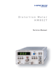
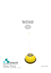
Solution de Monitoring Acoustique Solution for Sound Monitoring VES21 – BAP21 – PRE21W MANUEL D’UTILISATION / USER MANUAL MANUEL D’UTILISATION / USER MANUAL VES21 – BAP21 – PRE21 10 VES21 – PROTECTION CASE 10.1 Introduction The VES21 is a measurement station used for external sound measurements. The VES21 is used with Solo and other sound level meters type SIP95. The case protects the measurement devices against external climatic conditions (like rain, temperature and humidity). The case contains a high capacity battery which will power the sound level meter during 168 hours at +20°C (the battery lifetime depends on the ambient temperature and the sound level meter set-up). A charger is included, which can be used as a power supply, when longer periods are required. Warning: The charger is not weatherproof. In order to avoid a complete battery discharge during use, which can result in permanent damage, a battery monitoring system is used to cut the power supply when the voltage falls below a limit. The sound level meter then operates on an internal battery with a backup of memory data. Space is provided in the case for a rain shield, a microphone unit and an accessory (Modem GSM for example). Under the cap one can place cables, adapters and manuals. The whole equipment can be carried on-site like a stand-alone measurement unit. The package contains: a protection case IP54, a foam partitioning, a start and connection box, non user accessible batteries allowing SLM functioning, a 90 – 230V charger (multi-pays) / 6,7 V DC, a user manual (CDROM). 10.2 Operation This equipment works on 3 modes: On internal battery, On internal battery with charger, On external power supply (from 8 to 30 V DC: battery, solar panel, various supplies – refer to chapter “ Use with external power supply”). 0 BEFORE EACH MEASUREMENT SESSION IT IS ESSENTIAL TO RECHARGE THE BATTERY OF THE SOUND LEVEL METER SOLO OR TO REMOVE THE BATTERIES FROM THE SOUND LEVEL METERS TYPE SIP95/SLS95 (Refer to the user manual of these sound level meters for optimal use). VES21 – PROTECTION CASE PAGE 31 MANUEL D’UTILISATION / USER MANUAL VES21 – BAP21 – PRE21 11 GETTING STARTED THE SLM 11.1 Overview of the VES case Side view 1) 2) 3) 5) 6) 4) 7) 8) 9) 10) 11) 12) 13) 14) Ventilator Accessory compartment Control box Sound level meter (SOLO or SIP95) Preamplifier compartment 15) 16) 17) 18) Antenna connector Solo output connector (USB, RS232, Tacho, I/O see user manual of Solo) Charger connector / external power supply Extension cable connector of the microphone unit 11.2 Getting started Solo Remove the preamplifier of the SLM and place Solo in the compartment of the case. Connect the cables to the connectors: o 2 Pin-CONNECTOR for the power supply (connector at the back) o 10 Pin-CONNECTOR for accessories (connector at the back) o 7 Pin-CONNECTOR for the microphone extension cable (connector in front). o Connect the waterproof cable of the preamplifier to the 7-pin CONNECTEUR connector. 0 These operations have to be carried out with the VES in the Turn Off position. VES21 – PROTECTION CASE PAGE 32 MANUEL D’UTILISATION / USER MANUAL VES21 – BAP21 – PRE21 12 GETTING STARTED THE CONTROL BOX OF THE VES21 12.1 Overview of the control box 1) Push button 2) Red LED 3) Green LED 4) Orange LED The push button (1) is the switch that controls the operating of the system. According to the battery state (charged or discharged) pressing this push button launch a warning message indicated by a colored LED, which turns on (light emitting diode). In the following chapters we describe several cases possible. 12.2 Green LED Press the button during 1s, the green LED comes on. The SLM is supplied and the system is active. The battery and temperature control is ready. 12.3 Red LED When pressing the push button: 1. The red LED flashes regularly during 15 seconds: this indicates to the user that the power supply of the VES has been switched off because of too low internal battery. If after 15 seconds the green LED is going on the system is ready to operate, but the batteries have to be recharged. If the green LED does not turn on either the batteries are out of order or discharged. 2. The red LED flashes in intervals of three impulses: this means the VES21 has switched off the SLM power supply because of an internal temperature higher than 50°C (despite the forced ventilation). 3. The red LED remains switched on: this indicates a charge problem for the internal battery; the power supply is switched off. In case the problem persists, the control box is blocking the start of the system, contact your local 01dB agency. VES21 – PROTECTION CASE PAGE 33 MANUEL D’UTILISATION / USER MANUAL VES21 – BAP21 – PRE21 12.4 Orange LED The orange LED informs the user that the system receives enough energy (charger or external power supply) to supply the sound level meter, the accessories and recharge the internal battery of the VES21. This LED is used to verify the good connection of an external power source, if this source is turned off the system will be supplied from the internal battery. 12.5 Circuit diagram of the operating mode Press push button 1s si Internal power supply External power supply Green LED Orange/Green LED Red LED System OK Flashing 15s Flashing 3 impulses Steady Low internal Battery Internal T° too high Charge or battery problem After 15s Charger or extern. power supply OK Please contact the after-sales service Green LED If all LEDs are off System ready, but recharge is needed Recharge required System OK Press push button > 3 s (until the green LED is off) System Off VES21 – PROTECTION CASE PAGE 34 MANUEL D’UTILISATION / USER MANUAL VES21 – BAP21 – PRE21 13 SOLO SOUND LEVEL METER 13.1 Use with « Internal Battery » 13.1.1 Use 1) Press the push button of the control box during 1 s until the green LED is on. The system operates normally. 2) The user can then get the SLM started with the usual protocol (refer to the corresponding chapter of this user manual). 3) The system can be stopped, first by switching off the SLM, than by switching off the case, pressing the On/Off switch during 2 seconds (until the green LED is off). 13.1.2 Security In order to preserve the inner battery from a too important discharge, the system permanently controls its voltage. When the value is around 5 V the control box disconnects it automatically from the supply circuit. 0 Before each new measurement with a sound level meter it is imperative to recharge the batteries of the SLM and those of the VES21. 13.1.3 Operating The SLM switches to stand-by mode, if the battery voltage reaches 5 V. In this case, data stored in the SLM are saved. 13.1.4 Power supply of SOLO The SLM is supplied through the 6V control box via the 2 PIN CONNECTOR plug. Solo is equipped with a system to detect other power supply sources than that of its internal battery. The operating lifetime depends on its battery capacity and of that of the VES21. The internal battery of Solo has to be recharged before each new measurement session!!! The SLM indicates only the storage capacity, because the battery lifetime depends on parameters that are not calculated by the SLM during long-term measurements with the VES21. Measurement duration: Mode LAeq 1 s Spectra 1/1 1 s -10°C 108 h (4.5 d) 100 h (4.2 d) Temperature +20°C 180 h (7.5 d) 168 h (7 d) +50°C 144 h (6 d) 134 h (5.6 d) Operating lifetime of the system according to the measurement mode and the internal temperature. VES21 – PROTECTION CASE PAGE 35 MANUEL D’UTILISATION / USER MANUAL VES21 – BAP21 – PRE21 13.2 Use on « External power supply » 13.2.1 Use For long-term measurements an external power supply can be used (i.e. car battery). The voltage should be between 8 and 30 V DC. 1) Connect the external battery with a specific cable to the 3-Pin CONNECTOR plug, 2) The SLM can now be started, 3) In order to switch off the system, stop the SLM and the control box, and then disconnect the battery. 13.2.2 Security In order to preserve the inner battery from a too important discharge, the system controls permanently its voltage. When the value is around 5V the control box disconnects it automatically from the supply circuit. 0 Before each new measurement it is imperative to recharge the batteries of the SLM and of the VES21. 13.2.3 Operating In this configuration the electronic box also controls the status of the external power supply. The user verifies the status and the capacity of the external power supply for the selected measurement duration. The orange LED of the control box has to be lit (refer to the chapter “Getting started the SLM”) 13.2.4 Power supply The SLM only indicates the storage capacity, because the battery lifetime depends on parameters that are not calculated by the SLM during long-term measurements with the VES21. 13.3 Use on « Internal battery + charger » 13.3.1 Use When supply from the mains is available and for very long-term measurement, the charger delivered with the VES21 system may be used as external power supply. - Plug the charger into the special 3 Pin CONNECTOR plug, connect it to the mains and carry out the same operation as for the use with internal battery. 13.3.2 Security In order to preserve the battery situated inside, from a too important discharge, the system permanently controls its voltage. When the value is around 5V the control box disconnects it automatically from the supply circuit. 0 Before each new measurement it is imperative to recharge the batteries of the SLM and those of the VES21. VES21 – PROTECTION CASE PAGE 36 MANUEL D’UTILISATION / USER MANUAL VES21 – BAP21 – PRE21 13.3.3 Operating The functioning is the same as for use on “Internal Battery” (refer to the corresponding chapter). The only difference is the Orange LED lights up to indicate the recharging process of the VES21 batteries. 13.3.4 Power supply of the SLM The SLM indicates only the storage capacity, because the battery lifetime depends on parameters that are not calculated by the SLM during long-term measurements with the VES21. VES21 – PROTECTION CASE PAGE 37 MANUEL D’UTILISATION / USER MANUAL VES21 – BAP21 – PRE21 14 SOUND LEVEL METERS SIP95/SLS95S 14.1 Use on « Internal battery » 14.1.1 Use The operator has to push the button of the control box at least 1 second (the green LED has to light on) in order for the internal voltages to settle down. 5) The user can then get the SLM started with the usual protocol (refer to the chapter « Getting started the instrument » of the user manual). 4) 6) The system can be stopped, first by switching off the SLM, than by switching off the case, pressing the On/Off switch during 2 seconds (until the green LED is off). 14.1.2 Security In order to preserve the inner battery from a too important discharge, the system permanently controls its voltage. When the value is around 5V the control box disconnects it automatically from the supply circuit. 0 Before each new measurement it is imperative to remove the batteries of the SLM and those of the VES21. 14.1.3 Operating The SLM switches to stand-by mode, if the battery voltage reaches 10.8 V. In this case, data stored in the SLM are saved. 14.1.4 Power supply The power supply of sound level meters is delivered by a second power supply cable (12V). The sound level meters are equipped with a battery surveillance system for different operating phases. The residual charge of the batteries or accumulators is described in the corresponding chapters of the associated manuals. Measurement duration: Mode LAeq 1s Spectra 1/1 1s -10°C 78 h (3.25 d) 42 h (1.74 d) Temperature +20°C 130 h (5.4 d) 70 h (2.9 d) +50°C 104 h (4.3 d) 56 h (2.3 d) Operating lifetime of the system according to the measurement mode and the internal temperature. VES21 – PROTECTION CASE PAGE 38 MANUEL D’UTILISATION / USER MANUAL VES21 – BAP21 – PRE21 This information is not available when using the VES system. It is recommended to program the power supply mode in the SLM, in order to avoid perturbations for the operator in case of the low battery display: « External Battery » In this case, the SLM power supply is "unlimited" and depends directly on the capacity of the internal battery. In this case the display backlight is not switched off and the operating lifetime is only 130 h. The user has to manually program on the SLM in the “Utility” menu the stop of the backlight (refer to the manual). 14.2 Use on « External power supply » 14.2.1 Use For long-term measurements an external power supply can be used (i.e. car battery). The voltage should be between 8 and 30 V DC. 1) Connect the external battery with a specific cable to the 3-Pin CONNECTOR plug, 2) The user can now get started the SLM, 3) In order to switch off the system, stop the SLM and the control box, and then disconnect the battery. 14.2.2 Security In order to preserve the inner battery from a too important discharge, the system permanently controls its voltage. When the value is around 5 V the control box disconnects it automatically from the supply circuit. 0 Before each new measurement it is imperative to remove the batteries of the SLM and those of the VES21. 14.2.3 Operating In this configuration the electronic box controls also the state of the external power supply. The user verifies the state and the capacity of the external power supply for the selected measurement duration. The orange LED of the control box has to be lightened on (refer to the chapter “Getting started the SLM”) 14.2.4 Power supply of the SLM It is recommended to program the power supply mode for the SLM to: “ External Battery ” In this case the power supply is "unlimited" for the SLM and depends directly on the external battery capacity. VES21 – PROTECTION CASE PAGE 39 MANUEL D’UTILISATION / USER MANUAL VES21 – BAP21 – PRE21 14.3 Use on “Internal battery + Charger” 14.3.1 Use When mains are available and for long-term measurement, the charger delivered with the VES21 system may be used as external power supply. - Plug the charger to the dedicated 3 PIN CONNECTOR plug, and link it to the mains. Operate then as with the internal battery. 14.3.2 Security In order to preserve the inner battery from a too important discharge, the system controls permanently its voltage. When the value is around 5V the control box disconnects it automatically from the supply circuit. 0 Before each new measurement it is imperative to remove the batteries of the SLM and those of the VES21. 14.3.3 Functioning The functioning is the same as for use on “Internal Battery” (refer to the corresponding chapter). The only difference is the Orange LED lights up to indicate the recharging process of the VES21 batteries. 14.3.4 Power supply of the SLM It is recommended to program the power supply mode for the SLM to: “ External Battery ” In this case the power supply is "unlimited" for the SLM and depends directly on the external battery capacity. VES21 – PROTECTION CASE PAGE 40 MANUEL D’UTILISATION / USER MANUAL VES21 – BAP21 – PRE21 15 TECHNICAL SPECIFICATIONS 15.1 Technical specifications Case Weight (without sound level meter) 13 kg Dimensions (mm) 400 x 440 x 160 Internal Battery Type Waterproof lead accumulator without maintenance Rated Voltage 6V Capacity 52 Ah Charging cycle about 500 cycles Charging time 16 hours Charger Reference MASCOT 9920/9921 Power supply 90 –230 V single-phase, 50/60 Hz Rated voltage 6,7 V Output current limitation 3A 15.2 Output connectors pinning 8 PIN LEMO 3 PIN LEMO Ground USB+ Tachy IN USBGround TX 7 6 1 2 5 4 +5V USB 1 8 2 3 3 I/O 3V Charge Ground Ext. power RX 7 PIN LEMO Cal. (blue) V+ (red) V- (green) 6 1 NC 2 Ground (shield) 5 7 3 4 Signal (yellow) 200V (white) VES21 – PROTECTION CASE Ground PAGE 41 MANUEL D’UTILISATION / USER MANUAL VES21 – BAP21 – PRE21 16 CONNECTION CHART The sound level meter fits into the case, with connections for external voltage supply, the microphone input (7-PIN CONNECTOR), the USB output and the RS232. Sockets, which are protected by spring-loaded covers, are provided on the side of the case for charger connection, microphone extension cable and analogue/digital input/output (5-PIN CONNECTOR) as option (this means that data can be downloaded to the PC without having to unplug and remove the sound level meter from the case). A 3-pin connector / D-connector cable is provided for this purpose. CONNECTOR waterproof sockets are situated on the side of the case: - a a a a 7-PIN CONNECTOR plug to connect a microphone extension cable, 3-PIN CONNECTOR plug to connect the battery charger or an external power supply, BNC plug for a GSM antenna (as option), 8-PIN CONNECTOR plug for data (USB, RS232, Tacho in and I/O) PRE21W (Lémo 7 pts) GSM Output 6.7V DC 90-230V 50/60Hz RAL123-10M VES21 – PROTECTION CASE PAGE 42 MANUEL D’UTILISATION / USER MANUAL VES21 – BAP21 – PRE21 BAP21 – Weather screen 17 BAP21 – WEATHER SCREEN......................................................................................................................................45 17.1 17.2 17.3 17.4 17.5 17.6 Introduction......................................................................................................................45 Assembly Diagram.............................................................................................................45 Components of the BAP21 .................................................................................................46 Mounting of the BAP21 ......................................................................................................47 Frequency response ..........................................................................................................48 Directivity .........................................................................................................................48 BAP21 – BOULE PAGE 43 MANUEL D’UTILISATION / USER MANUAL VES21 – BAP21 – PRE21 17 BAP21 – WEATHER SCREEN 17.1 Introduction BAP21 consists of a stainless steel tube, a grid-supporting head, and a windscreen equipped with bird spikes. This accessory is designed for outdoor measurements since preamplifiers and microphones are protected against any weather. The shape of the protection tube was designed to provide BAP21 with acoustical properties compliant with the requirements of metrological precision classes. BAP21 can be used with any type of ½” preamplifier in the 01dB range, i.e., PRE21S, PRE21A, PRE12H, PRE12S, thus covering the whole range of measuring instruments (Solo, SIP95, SLS95S, Symphonie, Harmonie, Orchestra…). 17.2 Assembly Diagram 3 7 2 1 6 5 3 1 4 1) Unscrew the fixing screw of the protection tube. Insert the cord with the socket into the protection tube. 2) Connect the preamplifier to the microphone using the plug. 3) Slide the microphone-preamplifier set into the protection tube until you reach the end of the tube. 4) Place the cord in the notch and screw the cap to close the protection tube and block the cable into place. Check that the microphone is correctly positioned. 5) Screw the black grid prop on the protection tube to cover up the microphone. 6) Carefully place the windscreen on top of the black grid prop. 7) Screw the bird spikes on and fix the sliding ring. 8) Screw the whole set on the tripod. BAP21 – WEATHER SCREEN PAGE 45 MANUEL D’UTILISATION / USER MANUAL VES21 – BAP21 – PRE21 17.3 Components of the BAP21 BNN1010 BNN1009 MEC1212 References: BNN1010: bird protection BNN1009: wind screen MEK1212: black grid prop MEC1210: protection tube MEC1211: cap ACM1067: adapter MEC1210 MEC1211 ACM1067 BAP21 – WEATHER SCREEN PAGE 46 MANUEL D’UTILISATION / USER MANUAL VES21 – BAP21 – PRE21 17.4 Mounting of the BAP21 There are several mounting modes: 1) On tripod using a 3/8’’ thread or an adapter for a ¼’’ thread. Warning! Rain protection is ensured provided BAP21 is mounted vertically. 2) Using a clamp collar to fix the BAP21 on the support tube. View from above Support tube - for example: Transmission tower Aerial pole Clamp collar BAP21 – WEATHER SCREEN PAGE 47 MANUEL D’UTILISATION / USER MANUAL VES21 – BAP21 – PRE21 17.5 Frequency response The graph below shows the frequency response measured in an anechoic room for an angle of incidence of 0°. The microphone unit consists of a PRE21S preamplifier and a class 1 MCE 212 microphone capsule. Frequency response BAP21 (0°) 6,000 4,000 dB 2,000 0,000 -2,000 -4,000 -6,000 10,0 31,5 100,0 315,0 1000,0 3150,0 10000,0 Frequency (Hz) 17.6 Directivity Frequency response (30°) 6,00 4,00 dB 2,00 0,00 -2,00 -4,00 -6,00 80,00 250,00 800,00 2 500,00 8 000,00 1/6 octave (Hz) BAP21 – WEATHER SCREEN PAGE 48 MANUEL D’UTILISATION / USER MANUAL VES21 – BAP21 – PRE21 Frequency response (90°) 20,00 15,00 10,00 dB 5,00 0,00 -5,00 -10,00 -15,00 -20,00 80,00 250,00 800,00 2 500,00 8 000,00 1/6 octave (Hz) BAP21 – WEATHER SCREEN PAGE 49 MANUEL D’UTILISATION / USER MANUAL VES21 – BAP21 – PRE21 PRE21 - Preamplifier 18 PRE21W – PREAMPLIFIER .........................................................................................................................................52 18.1 18.2 18.3 18.4 Introduction......................................................................................................................52 Specifications....................................................................................................................52 Connection .......................................................................................................................53 Extension cable.................................................................................................................53 PRE21W – PREAMPLIFIER PAGE 51 MANUEL D’UTILISATION / USER MANUAL VES21 – BAP21 – PRE21 18 PRE21W – PREAMPLIFIER 18.1 Introduction PRE21S and PRE21W preamplifiers for ½” condenser microphones are designed to complement the sound level meter Solo of 01dB. There are two versions: PRE21S: for the Solo sound level meter only (long protection tube) The PRE21W is equipped with a heating system and a desiccator. It is compatible with field measurements. Depending on the external measurement it can be connected to BAP21 and/or VES21. Their electronic design allows the connection of long cables while maintaining an analysis bandwidth ranging up to 20 kHz. 18.2 Specifications Characteristics Supply voltage Supply power Input resistance Input capacitance Output resistance (for any f) PRE21S 10 - 40 <1 > 50 G < 0.2 < 100 PRE21W 20 - 30 20V→8 30V→12 > 50 G < 0.2 < 100 Unit V mA Ω pF Ω Bandwidth Extension cable type RAL122-100M 2 - 200 k 2 - 20 k 2 - 200 k Hz Hz < 3 (in dBA) < 15 (Lin 22 Hz-200 kHz) < 3 (in dBA) µV µV Background noise Gain (with 20 pF capacitance adapter) < 15 (Lin 22 Hz200 kHz) -0.2 -0.2 dB Polarization voltage 0/200 0/200 V Output charge capacitance < 20 < 20 NF Diameter 12.7 12.7 mm Length 100 100 mm Weight 30 30 g -15/+60 -25/+70 -20/+60 °C °C Operation Storage 0/90 0/95 0/95 0/95 % % Extension cable RAL122-10M RAL123-10 waterproof 10 10 m Temperature Operation Storage Hygrometry PRE21W – PREAMPLIFIER -25/+70 PAGE 52 MANUEL D’UTILISATION / USER MANUAL VES21 – BAP21 – PRE21 18.3 Connection PRE21S / PRE21W Output connector CONNECTOR-type pin / ref. : FGG1B307CLAZZZ Output connector pinning 18.4 Extension cable 0 Warning: The power supply of the heating resistance is the same as for the preamplifier, the maximum extension cable length is then 10 m, in order to avoid any voltage drop and to ensure a good operating of the preamplifier. PRE21W – PREAMPLIFIER PAGE 53