1
Lotus Service Notes
Section EMP
ENGINE MANAGEMENT
SECTION EMP
Sub-Section Page
Diagnostic Trouble Code List
EMP.1
3
Diagnostic Scanner Tools
EMP.2
43
Engine Management Component Location
EMP.3
47
Mechanical Throttle Setting Procedure
EMP.4
48
2006 Model Year Electronic Throttle Control
EMP.5
49
Diagnostic Trouble Code Supplement - '06 M.Y.
EMP.6
50
Diagnostic Trouble Code Supplement - 2011 M.Y. Elise (Euro 5)
EMP.7
58
Basic Functions of Lotus Scan 3 Tool
EMP.8
133
Page 1
Updated 12th September 2011
Lotus Service Notes
Section EMP
EMP.1 - DIAGNOSTIC TROUBLE CODE LIST
DTC
Fault description
Page
P0011
P0012 P0076
P0077
P0101
P0102
P0103
P0106
P0107
P0108
P0111
P0112
P0113
P0116
P0117
P0118
P0121
P0122
P0123
P0128
P0131
P0132
P0133
P0134
P0135
P0137
P0138
P0139
P0140
P0141
P0171
P0172
P0201
P0202
P0203
P0204
P0300
P0301
P0302
P0303
P0304
P0324
P0327
P0328
P0335
P0340
P0351
P0352
P0353
P0354
P0420
P0441
P0442
Camshaft Position - Timing Over-Advanced or System Performance Camshaft Position - Timing Over-Retarded Intake Valve Control Solenoid Circuit Low
Intake Valve Control Solenoid Circuit High
Mass or Volume Air Flow Circuit Range/Performance Mass or Volume Air Flow Circuit Low Input
Mass or Volume Air Flow Circuit High Input
Manifold Absolute Pressure/Barometric Pressure Circuit Range/Performance Manifold Absolute Pressure/Barometric Pressure Circuit Low Input
Manifold Absolute Pressure/Barometric Pressure Circuit High Input
Intake Air Temperature Sensor 1 Circuit Range/Performance Intake Air Temperature Sensor 1 Circuit Low Intake Air Temperature Sensor 1 Circuit High Engine Coolant Temperature Circuit Range/Performance Engine Coolant Temperature Circuit Low Engine Coolant Temperature Circuit High Throttle Position Sensor 'A' Circuit Range/Performance Throttle Position Sensor 'A' Circuit Low Throttle Position Sensor 'A' Circuit High Coolant Thermostat (Coolant Temperature Below Thermostat Regulating Temperature)
O2 Sensor Circuit Low Voltage (Pre Catalyst)
O2 Sensor Circuit High Voltage (Pre Catalyst)
O2 Sensor Circuit Slow Response (Pre Catalyst)
O2 Sensor Circuit No Activity Detected (Pre Catalyst)
O2 Sensor Heater Circuit (Pre Catalyst)
O2 Sensor Circuit Low Voltage (Post Catalyst)
O2 Sensor Circuit High Voltage (Post Catalyst)
O2 Sensor Circuit Slow Response (Post Catalyst)
O2 Sensor Circuit No Activity Detected (Post Catalyst)
O2 Sensor Heater Circuit (Post Catalyst)
System Too Lean
System Too Rich
Injector Circuit/Open – Cylinder 1
Injector Circuit/Open – Cylinder 2
Injector Circuit/Open – Cylinder 3
Injector Circuit/Open – Cylinder 4
Random/Multiple Cylinder Misfire Detected
Cylinder 1 Misfire Detected
Cylinder 2 Misfire Detected
Cylinder 3 Misfire Detected
Cylinder 3 Misfire Detected
Knock Control System Error
Knock Sensor 1 Circuit Low Knock Sensor 1 Circuit High Crankshaft Position Sensor “A” Circuit Range/Performance
Camshaft Position Sensor “A” Circuit
Ignition Coil “A” Primary/Secondary Circuit
Ignition Coil “B” Primary/Secondary Circuit
Ignition Coil “C” Primary/Secondary Circuit
Ignition Coil “D” Primary/Secondary Circuit
Catalyst System Efficiency Below Threshold
Evaporative Emission System Incorrect Purge Flow
Evaporative Emission System Leak Detected (small leak)
4
4
4
4
5
5
5
7
7
7
8
8
8
10
10
10
12
12
12
14
15
15
15
15
15
18
18
18
18
18
20
20
21
21
21
21
22
22
22
22
22
24
24
24
25
26
27
27
27
27
28
29
29
Page 2
Lotus Service Notes
Section EMP
DTC
Fault description
Page
P0444
P0445
P0446
P0447
P0448
P0451
P0452
P0453
P0455
P0456
P0461
P0462
P0463
P0480
P0481
P0500
P0506
P0507
P0508
P0509
P0562
P0563
P0601
P0606
P0627
P0646
P0647
P1301
P1302
P2602
P2603
P2646
P2647
P2648
P2649
Evaporative Emission System Purge Control Valve Circuit Open
Evaporative Emission System Purge Control Valve Circuit Shorted
Evaporative Emission System Vent Control Circuit
Evaporative Emission System Vent Control Circuit Open
Evaporative Emission System Vent Control Circuit Shorted
Evaporative Emission System Pressure Sensor/Switch Range/Performance
Evaporative Emission System Pressure Sensor/Switch Low Evaporative Emission System Pressure Sensor/Switch High Evaporative Emission System Leak Detected (large leak)
Evaporative Emission System Leak Detected (very small leak)
Fuel Level Sensor “A” Circuit Range/Performance
Fuel Level Sensor “A” Circuit Low Fuel Level Sensor “A” Circuit High Fan 1 Control Circuit
Fan 2 Control Circuit
Vehicle Speed Sensor “A”
Idle Air Control System RPM Lower Than Expected
Idle Air Control System RPM Higher Than Expected
Idle Air Control System Circuit Low
Idle Air Control System Circuit High
System Voltage Low
System Voltage High
Watchdog
Checksum
Fuel Pump Control Circuit /Open
A/C Clutch Relay Control Circuit Low
A/C Clutch Relay Control Circuit High
Misfire level causing emissions increase
Misfire level causing catalyst system damage
Coolant Pump Control Circuit Low
Coolant Pump Control Circuit High
A Rocker Arm Actuator System Performance or Stuck Off
A Rocker Arm Actuator System Stuck On
A Rocker Arm Actuator Control Circuit Low
A Rocker Arm Actuator Control Circuit High
31
31
31
31
31
31
31
31
29
29
32
32
32
33
33
34
35
35
35
35
36
36
37
37
38
39
39
40
40
41
41
42
42
42
42
When applicable, reference may be made under the 'Notes' heading to a page in the Toyota service manual.
This information should be used only for diagnosis and connection detail of the sensor. The Elise/Exige uses
a Lotus ECU, the connections for which may be found in circuit diagrams in Section MP. Diagnostic Trouble
Codes should be read using a Lotus Scan tool T000T1418F.
For 2006 M.Y. Trouble Codes see Section EMP.6
Page 3
Lotus Service Notes
Camshaft Timing Control (VVT)
P0011 P0012 P0076
P0077
Section EMP
P0011
P0012
P0076
P0077
Camshaft Position – Timing Over-Advanced or System Performance
Camshaft Position – Timing Over-Retarded
Intake Valve Control Solenoid Circuit Low
Intake Valve Control Solenoid Circuit High
Description
The Variable Valve Timing system (VVT) on the intake camshaft can vary the timing by approximately 25°. The
camshaft relative position is varied by a system of vanes mounted on the drive end of the camshaft. The VVT
oil control valve modulates a spool valve position in accordance with the drive signal duty cycle, this in turns
controls the oil pressure applied to the vanes. A 50% duty cycle applied to the valve will hold the valve current
timing by preventing oil flow from the VVT controller housing, a duty cycle less than 50% will retard the valve
timing, a duty cycle greater then 50% will advance the valve timing.
Component connections
Sensor Connector Description
1 Battery Voltage
2 VVT Oil Control Valve
P0011, P0012
ECU Pin
-
49(J3)
ECU Connector
52 Way (Right)
Monitor: Continuous
Enable Criteria:
• Engine running > 30 secs
• Coolant temperature > 60°C (140°F)
Disable Criteria:
P0116, P0117, P0118 – Coolant temperature fault codes
Potential failure modes:
• Static valve timing is incorrect
• VVT camshaft actuator failure
• VVT valve stuck open / closed
P0076, P0077
Monitor: Continuous
Enable Criteria: Engine running
Disable Criteria: None
Potential failure modes:
• VVT valve open circuit
• VVT valve short to ground
• ECU output circuit failure
Notes:
The MIL will be illuminated if the faults are present for 2 consecutive trips
Page 4
'06 M.Y. in brackets
Lotus Service Notes
Intake Air Flow
P0101
P0102
P0103
Section EMP
P0101
P0102
P0103
Mass or Volume Air Flow Circuit Range/Performance
Mass or Volume Air Flow Circuit Low Input
Mass or Volume Air Flow Circuit High Input
Description
The Mass Air Flow (MAF) sensor is incorporated into the airbox, and measures both intake air flow rate and
Intake Air Temperature (IAT). The MAF sensor uses a platinum hot wire and a cold wire element. By controlling the current flow through the hot wire to maintain a constant temperature, and therefore known resistance,
any change in air flow and therefore temperature, will be detected by a change in resistance. This change of
resistance is the output signal from the sensor.
Sensor connections
Sensor Connector
1
2
3
4
5
Description
Battery Voltage
MAF Ground
MAF Signal
IAT Signal
IAT Ground
ECU Pin
-
31(D2)
45(B4)
44(B3)
18(D2)
ECU Connector
52 Way (Right)
52 Way (Right)
52 Way (Right)
52 Way (Right)
'06 M.Y. in brackets
Sensor characteristics
0 – 655 g/sec
Typical values: 1.5 – 5.0 g/sec (idle), 5.0 – 15.0 g/sec (2500rpm elevated idle no load)
Monitor: Continuous.
P0101
Enable Criteria:
• Engine running
• Engine speed >2490rpm
• TPS > 80% (P0101 – MAPS* too low)
• TPS < 5% (P0101 – MAPS* too high)
*(MAPS – Mass Air Per Stroke)
Disable Criteria:
P0122, P0123, P0222, P0223 – Throttle/Pedal position fault codes
Potential failure modes:
• MAF sensor battery voltage open circuit (MAF value (g/sec) = 0.0)
• MAF sensor signal open circuit or short to ground (MAF value (g/sec) = 0.0)
• MAF sensor ground open circuit (MAF value (g/sec) > 229.0)
P0102
Enable Criteria: Engine running
Disable Criteria: None
Potential failure modes:
• MAF sensor battery voltage open circuit (MAF value (g/sec) = 0.0)
• MAF sensor signal open circuit or short to ground (MAF value (g/sec) = 0.0)
• MAF sensor ground open circuit (MAF value (g/sec) > 229.0)
Page 5
Lotus Service Notes
Section EMP
P0103
Enable Criteria: Engine running
Disable Criteria: None
Potential failure modes:
• MAF sensor battery voltage open circuit (MAF value (g/sec) = 0.0)
• MAF sensor signal open circuit or short to ground (MAF value (g/sec) = 0.0)
• MAF sensor ground open circuit (MAF value (g/sec) > 229.0)
Notes:
• The MIL will be illuminated if the faults are present for 2 consecutive trips
• Further information on the sensor may be found in Toyota 1ZZ-FE, 2ZZ-GE manual RM733E (B120T0327J)
Page DI-26 to DI-32
Page 6
Lotus Service Notes
Barometric Pressure
P0106
P0107
P0108
Section EMP
P0106
P0107
P0108
Manifold Absolute Pressure/Barometric Pressure Circuit Range/Performance
Manifold Absolute Pressure/Barometric Pressure Circuit Low Input
Manifold Absolute Pressure/Barometric Pressure Circuit High Input
Description
The barometric pressure sensor is located internally within the ECU, and measures atmospheric pressure. This
parameter is required to compensate the mass air flow when the vehicle is operated at higher altitudes.
Monitor: Continuous
P0106
Enable Criteria:
• Engine running
• Engine speed 2190 – 3510rpm
• TPS > 80%
Disable Criteria:
P0101, P0102, P0103 – MAF Sensor fault codes
P0121, P0122, P0123, P0222, P0223, P2135 – Throttle/Pedal position fault codes
Potential failure modes:
Sensor failure
P0107, P0108
Enable Criteria: Engine running
Disable Criteria: None
Potential failure modes:
Sensor failure
Notes:
The MIL will be illuminated if the fault is present for 2 consecutive trips
Page 7
Lotus Service Notes
Intake Air Temperature
Section EMP
P0111
P0112
P0113
P0111Intake Air Temperature Sensor 1 Circuit Range/Performance
P0112Intake Air Temperature Sensor 1 Circuit Low
P0113Intake Air Temperature Sensor 1 Circuit High
Description
The combined sensor which measure both Mass Air Flow (MAF) and Intake Air Temperature (IAT) is incorporated into the airbox. The IAT sensor is a thermistor device which changes resistance with temperature. As
air intake temperature decreases the thermistor resistance value increases, and conversely as air temperature
increases so the thermistor resistance value decreases.
Sensor connections
Sensor Connector
1
2
3
4
5
Description
Battery Voltage
MAF Ground
MAF Signal
IAT Signal
IAT Ground
ECU Pin
-
31 (D2)
45(B4)
44(B3)
18(D2)
ECU Connector
52 Way (Right)
52 Way (Right)
52 Way (Right)
52 Way (Right)
Sensor characteristics
IAT -20°C (-4°F) 12.5 – 16.9 kΩ
IAT 20°C (68°F) 2.19 – 2.67 kΩ
IAT 60°C (140°F) 0.50 – 0.68 kΩ
Monitor: Continuous
P0111
Enable Criteria:
• Engine running < 30 secs
• Coolant temperature < 30°C (86°F)
Disable Criteria:
P0116, P0117, P0118 – Coolant temperature fault codes
Potential failure modes:
• P0112 – signal short circuit
• P0113 – signal open circuit
• Sensor failure
P0112
Enable Criteria: Engine running
Disable Criteria: None
Potential failure modes:
• Signal short circuit (IAT = –40°C (–104°F) < 0.049 V)
• Sensor failure
Page 8
'06 M.Y. in brackets
Lotus Service Notes
Section EMP
P0113
Enable Criteria: Engine running
Disable Criteria: None
Potential failure modes:
• Signal open circuit (IAT > 140°C (284°F) > 4.932 V)
• Sensor failure
Notes:
• The MIL will be illuminated if the fault is present for 2 consecutive trips
• Further information on the sensor may be found inToyota 1ZZ-FE, 2ZZ-GE manual RM733E (B120T0327J)
pages DI-33 to DI-38
Page 9
Lotus Service Notes
Engine Coolant Temperature
P0116
P0117
P0118
Section EMP
P0116
P0117
P0118
Engine Coolant Temperature Circuit Range/Performance
Engine Coolant Temperature Circuit Low
Engine Coolant Temperature Circuit High
Description
The engine coolant temperature sensor is a thermistor device which changes resistance with temperature. As
coolant temperature decreases the thermistor resistance value increases, and conversely as coolant temperature increases so the thermistor resistance value decreases.
Sensor connections
Sensor Connector Description
1 Ground
2 Signal
ECU Pin
7 (H1)
33(C3) ECU Connector
52 Way (Right)
52 Way (Right)
Sensor characteristics
0°C (32°F) = 3.279 V
19.4°C (67°F) = 2.186 V
42.5°C (108.5°F) = 1.249 V
80°C (176°F) = 0.469 V
P0116
Enable Criteria:
Engine running > 800 seconds
Disable Criteria: None
Potential failure modes:
• P0117 – signal short circuit
• P0118 – signal open circuit
• Sensor failure
P0117
Enable Criteria: Engine running
Disable Criteria: None
Potential failure modes:
• Signal short circuit (Coolant Temperature = –40°C (–104°F) < 0.029 V)
• Sensor failure
P0118
Enable Criteria: Engine running
Disable Criteria: None
Potential failure modes:
• Signal open circuit (Coolant Temperature > 140°C (284°F) > 4.892 V)
• Sensor failure
Page 10
'06 M.Y. in brackets
Lotus Service Notes
Section EMP
Notes:
• The MIL will be illuminated if the fault is present for 2 consecutive trips
• Further information on the sensor may be found inToyota 1ZZ-FE, 2ZZ-GE manual RM733E (B120T0327J)
page DI-39 to DI-45
Page 11
Lotus Service Notes
Throttle Position
P0121
P0122
P0123
Section EMP
P0121
P0122
P0123
Throttle Position Sensor 'A' Circuit Range/Performance
Throttle Position Sensor 'A' Circuit Low
Throttle Position Sensor 'A' Circuit High
Description
The Throttle Position Sensor (TPS) is a potentiometer device, which is connected to a 5V reference source, a
ground and an input signal to the ECU.
Sensor connections
Sensor Connector
1
2
3
4
Description
Ground
5V Ref.
TPS1 Signal
TPS2 Signal
ECU Pin
34 (D1)
8 (M4)
20(D3)
(E3)
ECU Connector
52 Way (Right)
52 Way (Right)
52 Way (Right)
(Right)
Sensor characteristics
0% = 0.595 V ± 5%
100% = 4.148 V ± 5%
Monitor: Continuous.
P0121
Enable Criteria:
Rationality check – throttle not too high at low engine load:
• Engine running
• TPS > 80%
• Engine speed >1500rpm
• MAPS* < 40%
• Vehicle Speed > 30 km/h (18.6mph)
OR
Rationality check – throttle not too low at high engine load:
• Engine running
• TPS < 10%
• Engine speed 1500 – 2010rpm
• MAPS* > 65%
*(MAPS – Mass Air Per Stroke)
Disable Criteria:
P0101, P0102, P0103
P0500 P0016
– MAF Sensor fault codes
– Vehicle Speed sensor
– Crankshaft/Camshaft position correlation error
Potential failure modes:
• Sensor short or open circuit
• Sensor failure
Page 12
'06 M.Y. in brackets
Lotus Service Notes
Section EMP
P0122
Enable Criteria: None
Disable Criteria:
P0016 – Crankshaft/Camshaft position correlation error
Potential failure modes:
• Signal short circuit (< 0.283 V)
• Reference voltage open circuit
• Reference voltage short to ground
• Sensor failure
P0123
Enable Criteria: None
Disable Criteria:
P0016 – Crankshaft/Camshaft position correlation error
Potential failure modes:
• Signal open circuit (> 4.487 V)
• Reference voltage open circuit
• Reference voltage short to ground
• Sensor failure
Notes:
• The MIL will be illuminated if the fault is present for 2 consecutive trips
• Further information on the sensor may be found inToyota 1ZZ-FE, 2ZZ-GE manual RM733E (B120T0327J)
page DI-45 to DI-52
Page 13
Lotus Service Notes
Coolant Thermostat
P0128
Section EMP
P0128
Coolant Thermostat (Coolant Temperature Below Thermostat Regulating Temperature)
Description
The thermostat diagnostic is enabled after each cold engine start, and monitors the rate of temperature rise
during warm up relative to the measured engine air flow.
Monitor: Continuous
Enable Criteria:
• Engine running
• Coolant Temperature > -10°C (14°F)
• Coolant Temperature < 70°C (158°F)
Disable Criteria:
P116, P117, P118 – Engine Coolant Temperature sensor faults
Potential failure modes:
Thermostat failure
Notes:
The MIL will be illuminated if the fault is present for 2 consecutive trips.
Page 14
Lotus Service Notes
O2 Sensor (Pre Catalyst)
P0131
P0132
P0133
P0134
P0135
Section EMP
P0131
P0132
P0133
P0134
P0135
O2 Sensor 1 Circuit Low Voltage
O2 Sensor 1 Circuit High Voltage
O2 Sensor 1 Circuit Slow Response
O2 Sensor 1 Circuit No Activity Detected
O2 Sensor 1 Heater Circuit
Description
The oxygen sensor monitors the oxygen content in the exhaust gases. The sensor consists of a zirconia electrode between two platinum plates. When zirconia comes into contact with oxygen, it becomes an electrical
conductor. The exhaust gases pass through louvers in the sensor. One plate is in contact with the outside air
and the other plate is in contact with the exhaust gases. The platinum plate in contact with the air is electrically
negative due to the oxygen in the atmosphere and the plate in contact with the exhaust gases is electrically
positive. This will cause a difference in electrical potential to develop between the two plates. Thus the voltage
across the platinum plates ranges approximately from 100 millivolts to 900 millivolts, depending on the oxygen
content of the exhaust gases. Thus when the air/fuel mixture is rich, the oxygen sensor output will be high. If
the air/fuel mixture is lean, the oxygen sensor output will be low.
Sensor connections
Sensor Connector
1
2
3
4
Description
Signal
Ground
Heater Battery Voltage
ECU Pin
15 (A3)
41(F4)
1 (K3)
-
ECU Connector
52 Way (Left)
52 Way (Left)
52 Way (Left)
-
'06 M.Y. in brackets
Sensor characteristics
Normal operating range is 0 – 1000mV
Malfunction Criteria
P0131
Set when the sensor operates below 5mV for more than 1.5 seconds consecutively for a specified number of
times.
Monitor: Continuous
Disable Criteria: DFCO (Deceleration Fuel Cut Off)
Potential failure modes:
• Low fuel pressure (Lean mixture)
• Malfunctioning sensor
• External water on sensor
• Sensor wire shorted to ground
P0132
Set when the sensor operates above 1200mV for more than 1.5 seconds consecutively for a specified number
of times.
Monitor: Continuous
Page 15
Lotus Service Notes
Section EMP
Potential failure modes:
• High fuel pressure (Rich mixture)
• Leaking or shorted injector
• Purge valve fault
• Oxygen sensor contamination
• Engine oil contamination
• Sensor wire
P0133
Set when the sensor fails to switch from a Lean to a Rich condition or switch from a Rich to a Lean condition
in a sufficiently timely manner. A selection of switches is used to determine the average times.
Enable Criteria:
• Vehicle speed between 0 – 255 km/h (158.5 mph)
• MAF per stroke between 15 – 70 mg
• Engine speed between 2600 – 3511rpm
• Engine run time > 200 seconds
• Coolant temperature > 60°C (140°F)
• Closed loop fuelling enabled
Disable Criteria:
P0116, P0117, P0118 – Coolant temperature sensor faults
P0131, P0132, P0134, P0135 – Pre catalyst oxygen sensor faults
P0101, P0102, P0103 – MAF sensor faults
Monitor:
Monitored until the required amount of switches in both directions has been achieved (Approx. 150 sec)
Potential failure modes:
• Sensor connector and wiring should be checked for corrosion and loose connections
• Sensor contaminated, possibly from fuel, improper use of RTV, engine oil or coolant
P0134
Set when the sensor fails to switch above 557mV ('06 M.Y.; 675mV) and below 400mV within a 5.1 second
period for 5 consecutive checks ('06 M.Y.; within 60 sec).
Enable Criteria:
• Engine run time > 30 seconds
• Engine is not at idle
• Engine is in closed loop fuel control
Monitor:
Until either passed or failed (5.1 x 5 = 25.5 sec + initial 30 sec = 55 sec maximum).
Potential failure modes:
Sensor connector and wiring should be checked for corrosion and loose connections.
P0135
Set when the sensor output is greater than 1900mA or less than 250mA for 1.5 seconds, for 40 consecutive
checks.
Enable Criteria:
Engine run time > 60 seconds
Monitor:
Continuous
Page 16
Lotus Service Notes
Section EMP
Potential failure modes:
Sensor connector and wiring should be checked for corrosion and loose connections.
Notes:
• The MIL will be illuminated if the fault is present for 2 consecutive trips.
• Further information on the sensor may be found inToyota 1ZZ-FE, 2ZZ-GE manual RM733E (B120T0327J)
pages DI-53 to DI-62
Page 17
Lotus Service Notes
O2 Sensor (Post Catalyst)
P0137
P0138
P0139
P0140
P0141
Section EMP
P0137
P0138
P0139
P0140
P0141
O2 Sensor Circuit Low Voltage
O2 Sensor Circuit High Voltage
O2 Sensor Circuit Slow Response
O2 Sensor Circuit No Activity Detected
O2 Sensor Heater Circuit
Description
The oxygen sensor monitors the oxygen content in the exhaust gases. The sensor consists of a zirconia electrode between two platinum plates. When zirconia comes into contact with oxygen, it becomes an electrical
conductor. The exhaust gases passes through louvers in the sensor. One plate is in contact with the outside air
and the other plate is in contact with the exhaust gases. The platinum plate in contact with the air is electrically
negative due to the oxygen in the atmosphere and the plate in contact with the exhaust gases is electrically
positive. This will cause a difference in electrical potential to develop between the two plates. Thus the voltage
across the platinum plates ranges approximately from 100 millivolts to 900 millivolts, depending on the oxygen
content of the exhaust gases. Thus when the air/fuel mixture is rich, the oxygen sensor output will be high. If
the air/fuel mixture is lean, the oxygen sensor output will be low. The post catalyst oxygen sensor performance
is a good indicator of catalyst efficiency.
Sensor connections
Sensor Connector
1
2
3
4
Description
Signal
Ground
Heater Battery Voltage
ECU Pin
3 (B3)
29(F4)
27(H3)
-
ECU Connector
52 Way (Left)
52 Way (Left)
52 Way (Left)
-
'06 M.Y. in brackets
Sensor characteristics
Normal operating range is 0 – 1000mV
Malfunction Criteria
P0137
Set when the sensor operates below 5mV for more than 1.5 seconds consecutively for a specified number of
times.
Monitor: Continuous
Disable Criteria: DFCO (Deceleration Fuel Cut Off)
Potential failure modes:
• Check and rectify any pre catalyst sensor fault code, as they may be causing the fault code to be set
• Sensor wire shorted to ground
• Catalyst
P0138
Set when the sensor operates above 1200mV for more than 1.5 seconds consecutively for a specified number
of times.
Monitor: Continuous
Page 18
Lotus Service Notes
Section EMP
Potential failure modes:
• Check and rectify any front sensor fault code, as they may be causing the fault code to be set
• Catalyst
P0139
Set when the sensor fails to reach 650mV after 1.9 seconds of P.E or when the sensor fails to drop below
150mV after 5 seconds of DFCO ('06 M.Y.; Set when sensor fails to switch between 250mV and 650mV with
sufficient rapidity).
Enable Criteria:
• Engine run time > 200 seconds
• Coolant temperature > 60°C (140°F)
• Open loop fuel control
• DFCO (Deceleration Fuel Cut Off) followed by idle operation for 'lean to rich' switch
• DFCO for 'rich to lean' switch
Disable Criteria:
P0116, P0117, P0118 – Coolant Temperature Sensor faults
P0201, P0202, P0203, P0204 – Injector faults
P0300, P0301, P0302, P0303, P0304 – Misfire faults
P1301, P1302 – Misfire faults causing emission or catalyst damage
Monitor: Continuous, until the test is either passed or failed
Potential failure modes:
• Check and rectify any pre catalyst sensor fault code, as they may be causing the fault code to be set
• Catalyst
P0140
Set when the sensor fails to switch above 557mV and below 400mV within 60 seconds.
Enable Criteria:
• Engine run time > 30 seconds
• Engine is not at idle
• Engine is in closed loop fuel control
Monitor: Continuous
Potential failure modes:
• Check and rectify any front sensor fault code, as they may be causing the fault code to be set
• Sensor connector and wiring should be checked for corrosion and loose connections
• Catalyst
P0141
Set when the sensor output is greater than 1900mA or less than 250mA for 1.5 seconds, for 40 consecutive
checks.
Enable Criteria: Engine run time > 60 seconds
Monitor: Continuous
Potential failure modes:
Sensor connector and wiring should be checked for corrosion and loose connections
Notes:
• The MIL will be illuminated if the fault is present for 2 consecutive trips.
• Further information on the sensor may be found in Toyota 1ZZ-FE, 2ZZ-GE manual RM733E (B120T0327J)
pages DI-63 to DI-66
Page 19
Lotus Service Notes
Fuel Control System Too Lean Or Rich
P0171 System Too Lean
P0172 System Too Rich
Section EMP
P0171
P0172
Description
The oxygen sensor sends a signal to the ECU corresponding to the exhaust gas oxygen content enabling the
ECU to maintain a 14.7:1 air/fuel ratio under normal driving conditions. The ECU can make fuel corrections
of ± 17% to the calculated fuel demand. If the ECU determines a rich condition exists (oxygen sensor above
0.450mV), it will decrease the calculated fuel demand to maintain a 14.7:1 ratio. If the ECU determines a lean
condition exists (oxygen sensor below 0.450mV), it will increase the calculated fuel demand to maintain a
14.7:1 ratio.
Enable Criteria
• Fuel Trim condition enabled
• Closed loop fuelling enabled
• Engine speed > 1100 rpm
• MAF > 6 g/sec
• Engine load < 70 %
• Altitude < 8000 ft (2438 m), Baro > 756 mbar
• Inlet air temperature > -10°C (14°F)
Disable Criteria
P0106, P0107, P0108 – Baro sensor faults
P0111, P0112, P0113 – Air Intake Sensor faults
P0131, P0132, P0133, P0134, P0135 – Oxygen sensor faults
P0300, P0301, P0302, P0303, P0304 – Misfire faults
P0441, P0442, P0443, P0447, P0448, P0450, P0451, P0455, P0456 – EVAP faults
Monitor: Continuous
Malfunction Criteria
P0171
This code is set when the calculated fuel demand has been increased to its maximum limit of 17% and the
system still cannot maintain an air/fuel ratio of 14.7:1 under normal driving conditions.
Potential failure modes:
• Fuel Pressure too low
• Air leak in system
• Water in fuel
• Exhaust leak / crack before front oxygen sensor
• Injector fault
• Sensor connector and wiring for signs of corrosion or loose connections
P0172
This code is set when the calculated fuel demand has been decreased to its minimum limit of -17% and the
system still cannot maintain an air/fuel ratio of 14.7:1 under normal driving conditions.
Potential failure modes:
• Fuel Pressure too high
• Leaking fuel injector
• Restriction in the exhaust system or air intake / filter
• Erratic throttle position sensor
Notes:
• The MIL will be illuminated if the fault is present for 2 consecutive trips.
• Further information on the sensor may be found inToyota 1ZZ-FE, 2ZZ-GE manual RM733E (B120T0327J)
pages DI-67 to DI-72
Page 20
Lotus Service Notes
Fuel Injection System
P0201
P0202
P0203
P0204
Section EMP
P0201
P0202
P0203
P0204
Injector Circuit/Open – Cylinder 1
Injector Circuit/Open – Cylinder 2
Injector Circuit/Open – Cylinder 3
Injector Circuit/Open – Cylinder 4
Description
The ECU has four injector driver circuits, each of which controls an injector. When the engine is running the
ECU continuously monitors the injector circuit feedback signals. The feedback signal should be low when the
injector is ON and high voltage when the injector is OFF.
Component connections
Injector ECU Pin ECU Connector
1 25(J1) 52 Way (Right)
2 51(K4) 52 Way (Right)
3 14(K3) 52 Way (Right)
4 40(K2) 52 Way (Right)
'06 M.Y. in brackets
Malfunction Criteria
The operation of all the injector codes is the same, the last digit relates to the injector involved i.e. a code P0203
indicates there is a problem with injector number 3.
Enable Criteria: Engine running
Monitor: Continuous
Limp home:
• Limit maximum engine speed to 6000rpm
• Return the fuel system to open loop fuel control
Potential failure modes:
Sensor connector or wiring corroded or loose connections
Notes:
• The MIL will be illuminated if the fault is present for 2 consecutive trips.
• If an injector goes short circuit it is likely that the ECU injector driver will be damaged.
Page 21
Lotus Service Notes
Misfire
P0300
P0301
P0302
P0303
P0304
Section EMP
P0300
P0301
P0302
P0303
P0304
Random/Multiple Cylinder Misfire Detected
Cylinder 1 Misfire Detected
Cylinder 2 Misfire Detected
Cylinder 3 Misfire Detected
Cylinder 4 Misfire Detected
Description
A misfiring cylinder can be detected by analysing crank speed variation. As a result of a combustion event there
will be a net acceleration of the crankshaft. Subsequent to a misfire event the engine will decelerate over the
period following the missed cylinder event.
Speed changes can be characterised by observing changes in the time period for a fixed angle of rotation after
firing events. A significant change in this period, assessed by comparison to previous periods, may be attributed
to misfire on a known cylinder.
Component connections '06 M.Y. in brackets
Connector Description ECU Pin ECU Connector
1 Supply Voltage Coil 1 Coil 2 Coil 3 Coil 4
2 Ignition Coil Feedback 22 (F3) 22 (F3) 22 (F3) 22 (F3) 52 Way (Right)
3 Coil Output (Logic) 52(G1) 26 (G4) 47 (G3) 48 (G2) 52 Way (Right)
4 Ground
Malfunction Criteria
The operation of all the misfire codes is the same, the last digit relates to the misfire involved i.e. a code P0303
indicates there is a problem with coil number 3. P0300 indicates the misfire is random and not linked to one
particular cylinder.
Enable Criteria:
• Battery voltage between 10 – 16 V
• Coolant temperature between -10 – 120°C (14 – 248°F)
• Engine speed between 660 – 8010rpm
• Engine speed transient > 15rpm
• Altitude < 8000 ft (2438 m) / Baro > 756mbar
• Fuel level > 5 litres (1.3 US gallons)
• Engine load between 15 – 48% depending on engine speed
Disable Criteria: DFCO enabled (Deceleration Fuel Cut Off)
Monitor: Continuous
Limp home:
• Limit maximum engine speed to 6000 rpm
• Return the fuel system to open loop
• ECU may deactivate two cylinders, the misfiring cylinder and it’s matched other i.e. 1 & 4 or 2 & 3.
Potential failure modes:
• Injector related codes, as these can cause misfire codes to be set.
• VVT or VVL codes set
• Sensor connector and wiring for signs of corrosion or loose connections
• Spark plug / Cylinder compression
• Cam timing / Damage to rocker arm assembly
Page 22
Lotus Service Notes
Section EMP
Notes:
• The MIL will be illuminated if the fault is present for 2 consecutive trips.
• Further information on the sensor may be found inToyota 1ZZ-FE, 2ZZ-GE manual RM733E (B120T0327J)
pages DI-73 to DI-78
Page 23
Lotus Service Notes
Knock Control System
P0324
P0327
P0328
Section EMP
P0324
P0327
P0328
Knock Control System Error
Knock Sensor 1 Circuit Low
Knock Sensor 1 Circuit High
Description
The knock sensor contains a piezoelectric element which generates a voltage when it becomes deformed. The
piezoelectric element sends the signal to the ECU, when the cylinder block vibrates due to engine knocking.
If knock is detected then the ECU will retard the ignition to suppress it. The knock control sensor cannot differentiate between spark knock and other similar sounding noises.
Sensor connections
Sensor Connector Description
1 Sensor input
2 Ground
ECU Pin
43(C4)
13(A4)
ECU Connector
52 Way (Right)
52 Way (Right)
'06 M.Y. in brackets
Malfunction Criteria
P0327 – This code is set when the knock sensor signal is < 0.586 V
P0328 – This code is set when the knock sensor signal is > 2.928 V
Potential failure modes:
• Abnormal engine noise, i.e. damaged engine or exhaust system contacting vehicle
• Knock sensor fixing too tight
• Sensor connector / wiring corroded or loose connections
Notes:
• The MIL will be illuminated if the fault is present for 2 consecutive trips.
• Further information on the sensor may be found inToyota 1ZZ-FE, 2ZZ-GE manual RM733E (B120T0327J)
pages DI-79 to DI-81
Page 24
Lotus Service Notes
Engine Speed / Position Sensors
P0335
Section EMP
P0335
Crankshaft Position Sensor “A” Circuit Range/Performance
Description
Engine speed is calculated by measuring the time between the ‘teeth’ of the crankshaft sensor trigger disc. The
disc has 34 ‘teeth’ and 2 missing ‘teeth’, spaced at 10 degree intervals around the disc. The 2 missing ‘teeth’
are positioned at 225 degrees before cylinder No.1 and 4 TDC. The crankshaft sensor signal is also used to
determine misfires events.
Sensor connections
Sensor Connector Description
1 Sensor input
2 Ground
ECU Pin
4 (E1)
30(E4)
ECU Connector
52 Way (Right)
52 Way (Right)
'06 M.Y. in brackets
Monitor: Continuous
Enable Criteria: Engine running
Disable Criteria: None
Potential failure modes:
• Sensor signal open circuit or short to ground
• Sensor ground open circuit
• Sensor failure
Notes:
• If a sensor or sensor circuit failure occurs, the engine will not fire or start.
• The MIL will be illuminated if the fault is present for 2 consecutive trips
• Further information on the sensor may be found inToyota 1ZZ-FE, 2ZZ-GE manual RM733E (B120T0327J)
pages DI-82 to DI-83
Page 25
Lotus Service Notes
Engine Speed / Position Sensors
P0340
Section EMP
P0340
Camshaft Position Sensor “A” Circuit
Description
The camshaft position input to the ECU is used to determine engine phase, enable sequential fuel injection
control and to determine camshaft position for the VVT system. The inlet camshaft has three ‘teeth’ spaced 90°
apart, which are detected by the electromagnetic sensor. The valve timing setting is measured in the ECU by
measuring time from a (fixed position) crankshaft tooth to a (variable position) camshaft tooth. As the engine
speed and the position is known from the crankshaft sensor signal, the camshaft position can be calculated.
Sensor connections
Sensor Connector Description ECU Pin
1 Signal(VR Input) 16(C1)
2 Ground 42(E2)
ECU Connector
52 Way (Right)
52 Way (Right)
'06 M.Y. in brackets
Monitor: Continuous
Enable Criteria:
• Engine running
• Engine speed > 600rpm
Disable Criteria: None
Potential failure modes:
• Sensor signal open circuit or short to ground
• Sensor ground open circuit
• Sensor failure
Notes:
• The MIL will be illuminated if the fault is present for 2 consecutive trips.
• Further information on the sensor may be found in Toyota 1ZZ-FE, 2ZZ-GE manual RM733E (B120T0327J)
pages DI-84 to DI-85
Page 26
Lotus Service Notes
Ignition System
P0351
P0352
P0353
P0354
Section EMP
P0351
P0352
P0353
P0354
Ignition Coil “A” Primary/Secondary Circuit
Ignition Coil “B” Primary/Secondary Circuit
Ignition Coil “C” Primary/Secondary Circuit
Ignition Coil “D” Primary/Secondary Circuit
Description
A Direct Ignition System (DIS) is used on the engine. The DIS improves the ignition accuracy, reduces highvoltage loss, and enhances the reliability of the ignition system. The DIS is a 1-cylinder system that ignites one
cylinder with one ignition coil. The ECU determines the ignition timing and outputs the ignition signals (IGT) for
each cylinder. Based on IGT signals, the power transistors in the igniter cuts off the current to the primary coil,
which induces a spark at the spark plug connected to the secondary coil. The igniter will also send an ignition
confirmation signal (IGF) as a fail-safe measure to the ECU.
Component connections '06 M.Y. in brackets
Connector Pin Description ECU Pin ECU Connector
1 Supply Voltage Coil 1 Coil 2 Coil 3 Coil 4
2 Ignition Coil Feedback 22 (F3) 22 (F3) 22 (F3) 22 (F3) 52 Way (Right)
3 Coil Output (Logic) 52(G1) 26(G4) 47 (G3) 48 (G2) 52 Way (Right)
4 Ground
Malfunction Criteria
No IGF signal to ECM while engine is running
Potential failure modes:
• Open or short in IGF1 – IGF4 circuit from ignition coil to ECU
• Coil failure
Notes:
• The MIL will be illuminated if the fault is present for 2 consecutive trips.
• Further information on the sensor may be found inToyota 1ZZ-FE, 2ZZ-GE manual RM733E (B120T0327J)
pages DI-97 to DI-103
Page 27
Lotus Service Notes
Catalyst System Efficiency
P0420
Section EMP
P0420
Catalyst System Efficiency Below Threshold
Description
The ECU compares the waveform of the oxygen sensors located before and after the catalyst to determine
whether or not the catalyst has deteriorated. If the catalyst is functioning normally the front oxygen sensor will
be switching between rich and lean whilst the rear oxygen sensor should also be switching between rich and
lean but more slowly. When both the oxygen sensor waveforms change at the same rate, it indicates that the
catalyst performance has deteriorated. The ECU counts the number of pre and post catalyst oxygen sensor
switches and divides one by the other to determine a ratio number. If the ratio number is greater than 0.6 ('06
M.Y.; 0.165) the code is set.
Sensor connections
Pre catalyst oxygen sensor
Sensor Connector Description
1 Signal
2 Ground
3 Heater Supply
4 Battery Voltage
ECU Pin
15 (A3)
41(F4)
1 (K3)
-
ECU Connector
52 Way (Left)
52 Way (Left)
52 Way (Left)
-
'06 M.Y. in brackets
Post catalyst oxygen sensor
Sensor Connector Description
1 Signal
2 Ground
3 Heater Supply
4 Battery Voltage
ECU Pin
3 (B3)
29(F4)
27(H3)
-
ECU Connector
52 Way (Left)
52 Way (Left)
52 Way (Left)
-
'06 M.Y. in brackets
Malfunction Criteria
• Closed loop fuel control enabled
• Coolant temperature > 60 °C (140 °F)
• Baro > 756 mbar
• Vehicle speed < 130 km/h (81 mph)
• MAF < 40 g/sec
• Air inlet temp > -10°C (14°F)
Disable Criteria:
P0101, P0102, P0103 – MAF faults
P0107, P0108 – MAP / Baro Faults
P0116, P0117, P0118 – Coolant temperature faults
P0131, P0132, P0133, P0134, P0135, P0137, P0138, P0139, P0140, P0141– Oxygen sensor faults
P0171, P0172 – Fuelling faults
P0300, P0301, P0302, P0303, P0304 – Misfire faults
Potential failure modes:
• Exhaust system leak
• Oxygen sensor faults
• Oxygen sensor heater failure
• Catalyst failure
Notes:
• The MIL will be illuminated if the fault is present for 2 consecutive trips.
• Further information on the sensor may be found inToyota 1ZZ-FE, 2ZZ-GE manual RM733E (B120T0327J)
pages DI-86 to DI-88
Page 28
Lotus Service Notes
Evaporative Emission Control – Leak Detection System
P0441
P0442
P0455
P0456
Section EMP
P0441
P0442
P0455
P0456
Evaporative Emission System Incorrect Purge Flow
Evaporative Emission System Leak Detected (small leak)
Evaporative Emission System Leak Detected (large leak)
Evaporative Emission System Leak Detected (very small leak)
Description
During an Evaporative Emission System Leak Detection check, the vacuum in the system is monitored by ECU
using the fuel tank pressure sensor. At the appropriate time, the test starts with the ECU closing the canister
closure value and opening the purge solenoid with the appropriate duty cycle. This allows the engine to draw
a vacuum on the entire evaporative emission system. After a calibrated vacuum level is achieved the purge
solenoid is closed, sealing the system. A leak is detected by monitoring any decrease in vacuum level over a
calibrated period of time.
Sensor / component connections
Vapour Pressure sensor
Connector Pins Description
1 Ground
2 Signal
3 5V V. Ref.
ECU Pin
78 (L4)
75(C1)
55(M4)
ECU Connector
28 Way (Left)
28 Way (Left)
28 Way (Left)
Purge Canister Closure Valve
Connector Pins Description
A Battery Voltage
B ECU ground
ECU Pin
-
9 (H2)
ECU Connector
52 Way (Left)
'06 M.Y. in brackets
Purge Solenoid
Connector Pins
A
B
ECU Pin
-
38 (F4)
ECU Connector
52 Way (Right)
'06 M.Y. in brackets
Description
Battery Voltage
ECU ground
'06 M.Y. in brackets
Enable Criteria:
• Altitude < 8000 ft (2438 m), Baro > 700 mbar
• Coolant > 45°C (113°F)
• Air temp < 80°C (176°F)
• Fuel level between 8 – 35 litres (2.1 – 9.24 US gallons)
• Vehicle must be stationary
• Closed loop fuelling control enabled
• Closed loop idle speed control enabled
• Ignition on
Disable Criteria:
P0171, P0172 P0441, P0444, P0445 P0446, P0447, P0448 P0451, P0452, P0453 P0461, P0462, P0463
P0500 – Fuel trim too rich or lean soft code
– Purge faults
– Canister closure faults
– Tank Pressure sensor faults
– Fuel level sensor faults
– Vehicle speed faults
Malfunction Criteria
P0441
This code can be caused by the purge value being either stuck closed or open.
Page 29
Lotus Service Notes
Section EMP
Purge valve stuck open
A purge valve that is unable to seal correctly will result in a tank evacuation during the sealing phase of the
leak check sequence. In this phase, a pressure rise would normally be expected but when the purge valve
is not sealing this causes depression in the tank. When the pressure is below -1.7mbar a purge valve fault is
detected.
Purge valve stuck closed
A purge valve that is unable to open will not be able to achieve the required depression during the evacuation
phase. A positive pressure rise during the leak check evacuation phase will be detected. Additional purge checks
will set a purge valve fault code.
Monitor: Until leak check is completed
P0442
This code is set during the evaporative leak check process if the system calculates the measure of leak is above
a specified value (determined by a table related to fuel level) after the 6.3 second timer has expired.
Monitor: Until leak check is completed
Potential failure modes:
• Leak from pipes or connections
• Leaking or damaged seal on filler cap / not fitted correctly
• Canister Closure valve not fully closing
P0455
This code is set if during the evaporative leak check the system fails to reach the evacuation target pressure.
The system will perform additional purge checks to determine the nature of the problem. The additional purge
checks will also run if the leak check fails to complete because the calculated vapour concentration is above
the limit.
Additional Purge Check Enable Criteria:
• Vehicle not stationary
• Load between 30 – 35%
• Purge value >= 75%
Monitor: Until leak check is completed
Potential failure modes
• Fuel filler cap not fitted
• Leak from pipes or connections
• Canister Closure valve stuck open
P0456
This code is set during the evaporative leak check process if the system calculates the measure of leak is above
a specified value (determined by a table related to fuel level) after the 19.7 second timer has expired.
Monitor: Until leak check is completed
Potential failure modes:
• Leak from pipes or connections
• Leaking or damaged seal on filler cap / not fitted correctly
• Canister Closure valve not fully closing
Notes:
• The MIL will be illuminated if the fault is present for 2 consecutive trips.
• Further information on the sensor may be found in Toyota 1ZZ-FE, 2ZZ-GE manual RM733E (B120T0327J)
page FI-53
Page 30
Lotus Service Notes
Evaporative Emission Control – Purge, Open / Closed Circuit
P0444
P0445
P0446
P0447
P0448
P0451
P0452
P0453
Section EMP
P0444
P0445
P0446
P0447
P0448
P0451
P0452
P0453
Evaporative Emission System Purge Control Valve Circuit Open
Evaporative Emission System Purge Control Valve Circuit Closed
Evaporative Emission System Vent Control Circuit
Evaporative Emission System Vent Control Circuit Open
Evaporative Emission System Vent Control Circuit Closed
Evaporative Emission System Pressure Sensor/Switch Range/Performance
Evaporative Emission System Pressure Sensor/Switch Low
Evaporative Emission System Pressure Sensor/Switch High
Description
When the engine is running the ECU continuously monitors the feedback signals from the evaporative emission
components. The feedback signal should be low when the turned ON and high when turned Off. The following
codes will be set if the above conditions are not met.
P0444, P0445, P0447, P0448, P0452, P0453
P0446
This code can be caused by the canister closure valve (CCV) being either stuck closed or open.
CCV stuck open:
A CCV is stuck open then there will be minimal tank depression when the leak test is performed. Addition check
will be performed when the vehicle is being driven before the code is set.
CCV stuck closed:
Detection of a stuck closed CCV is implemented by detecting an excessively low tank pressure during normal
purge. Detection of this fault will disable further purging
Additional checks for stuck CCV closed:
• Vehicle not stationary
• Load between 30 – 35%
• Purge Value >= 75%
Monitor: Until leak check is completed.
P0451
This code is set when the ECU detects abnormalities in the fuel tank vapour pressure sensor signal. The ECU
analyses the filtered and unfiltered pressure signal at idle after a de-slosh period to determine if there is any
difference, a big difference indicates as fault. The ECU also monitors the signal on gear changes to see if there
is any pressure rise as a result of the fuel sloshing around.
Disable Criteria:
P0500 – Wheel speed sensor fault
Monitor: Until leak check is completed
Notes:
The MIL will be illuminated if the fault is present for 2 consecutive trips.
Page 31
Lotus Service Notes
Fuel Level Sensor
P0461
P0462
P0463
Section EMP
P0461
P0462
P0463
Fuel Level Sensor “A” Circuit Range/Performance
Fuel Level Sensor “A” Circuit Low
Fuel Level Sensor “A” Circuit High
Description
When the engine is running the ECU continuously monitors the fuel level sensor feedback signals. The feedback
signal should be low when turned ON and high when turned OFF. The following codes will be set if the above
conditions are not meet.
Sensor connections
Sensor Connector Description
1 Vapour pressure and fuel level ground
2 Fuel level sensor
3 Vapour pressure & fuel level V ref. '06 M.Y. in brackets
ECU Pin ECU Connector
78 (L4) 28 Way (Left)
76(E3) 28 Way (Left)
55(M4) 28 Way (Left)
Enable Criteria:
• P0462 & P0463 – Condition not met as above
• P0461 – Checks for three conditions, stuck when full, stuck when empty or stuck midway. The ECU determines
if the sensor is stuck by calculating the amount of fuel used during the test period with the engine conditions
as listed below.
• RPM > 2800rpm
• Load > 40%
• Minimum Fuel level > 2 litres (0.5 US gallons)
• If the ECU calculates that no fuel has been used during these tests it indicates that the sensor is not working correctly. The ECU also monitors the filtered and unfiltered signal at idle after a 10 second de-slosh period
and compares the differences. Gear changes cause the fuel to slosh around so the ECU monitors the signal
to see if there is any pressure rise.
Disable Criteria:
P0500 – Wheel speed sensor fault
Notes:
The MIL will be illuminated if the fault is present for 2 consecutive trips.
Page 32
Lotus Service Notes
Engine Cooling Fan Control
P0480
P0481
Section EMP
P0480
P0481
Fan 1 Control Circuit
Fan 2 Control Circuit
Component connections
Sensor Connector Description
2 (ACCM 2*) Relay #1 3 (ACCM 2*) Relay #2 ECU Pin
67 (J2) 60(J3) ECU Connector
28 Way (Left) 28 Way (Left)
'06 M.Y. in brackets
*ACCM – A/C Control Module
Monitor: Continuous
Enable Criteria: Engine running
Disable Criteria: None
Potential failure modes:
• A/C Control Module failure
• ECU output circuit failure
Notes:
No MIL will be illuminated for this failure.
Page 33
Lotus Service Notes
Vehicle Speed Sensor
P0500
Section EMP
P0500
Vehicle Speed Sensor “A”
Description
The ECU uses the left rear wheel speed sensor to determine vehicle speed. This output to the ECU is via the
ABS module.
Sensor connections
ABS Control Unit Description
3 Wheel Speed 3 from ABS (LR)
ECU Pin
77(B4)
ECU Connector
28 Way (Left) '06 M.Y. in brackets
Sensor characteristics
Hall Effect sensor
Malfunction Criteria
• TPS < 0.8
• Engine speed > 1800rpm and < 5010rpm
• Baro > 756 mbar
Monitor: Continuous
Potential failure modes:
• Open or short in vehicle speed sensor circuit
• Build up of debris in the sensing plate on the wheel hub
Notes:
The MIL will be illuminated if the fault is present for 2 consecutive trips.
Page 34
Lotus Service Notes
Idle Speed Control
P0506
P0507
P0508
P0509
Section EMP
P0506
P0507
P0508
P0509
Idle Air Control System RPM Lower Than Expected
Idle Air Control System RPM Higher Than Expected
Idle Air Control System Circuit Low (prior '06 M.Y.)
Idle Air Control System Circuit High (prior '06 M.Y.)
Description
Prior to '06 M.Y. the ECU controls the air entering the engine with an idle air control (IAC) valve. To increase the
idle the ECU commands the IAC to open up. This allows more air to bypass the throttle blades. To decrease
the idle speed the ECU commands the IAC to close up. This will reduce the amount of air bypassing the throttle
body. The ECU performs low and high circuit checks when it is activating the component.
For '06 M.Y. onwards, the electronically controlled throttle needs no IAC, as the ECU commands the throttle
valve itself to control idle speed.
Component connections (prior to '06 M.Y.)
Connector Description ECU Pin
1 Idle air control value 35
2 Battery Voltage -
3 Ground -
ECU Connector
52 Way
-
Malfunction Criteria
P0506 – This code is set if the engine fails to achieve the desired idle speed by more than 100 rpm.
P0507 – This code is set if the engine fails to achieve the desired idle speed by more than 200 rpm.
P0508 – This is set when the ECU does not get the expected feedback (prior to '06 M.Y.).
P0509 – This is set when the ECU does not get the expected feedback (prior to '06 M.Y.).
Enable Criteria:
• Engine at idle speed
• Battery Voltage between 10 – 16 V
• Idle speed learn limit ± 15%
• Timer expired 5 seconds
Monitor: Continuous
Potential failure modes:
• Throttle body sticking (not fully closing) (prior to '06 M.Y.)
• Connector / wiring corroded or loose connections (prior to '06 M.Y.)
• Throttle linkage / cable binding (prior to '06 M.Y.)
• Induction system air leak
• Excessive engine load from front end accessory drive system, e.g. water pump seizing
Notes:
The MIL will be illuminated if the fault is present for 2 consecutive trips.
Page 35
Lotus Service Notes
Battery Voltage
P0562
P0563
P0562
P0563
System Voltage Low
System Voltage High
Monitor: Continuous
Enable Criteria:
• Engine running
• P0562 – Voltage Too Low < 10V
• P0563 – Voltage Too High > 16V
Disable Criteria: None
Potential failure modes:
• Alternator fault
• Battery fault
Notes:
The MIL will be illuminated if the fault is present for 2 consecutive trips.
Page 36
Section EMP
Lotus Service Notes
ECU Integrity
P0601
P0606
Section EMP
P0601
P0606
Checksum
Watchdog
Description
These codes are used by the ECU to check the integrity of the software and calibration data. P0601 checks
that on power up the checksum for calibration data is the same as checksum saved on power down. P0606
checks the watchdog timer after a defined period to see if it has reset. If the watchdog timer has not reset then
the code has entered an unplanned loop or condition stopping it resetting the timer.
Monitor
• P0601 at ECU power up
• P0606 continuously while the engine running
Notes:
The MIL will be illuminated if the fault is present for 2 consecutive trips.
Page 37
Lotus Service Notes
Fuel Pump
P0627
Section EMP
P0627
Fuel Pump Control Circuit /Open
Description
The fuel system is of the non-return type. The pump is incorporated into the fuel tank module which also contains the level sensor, regulator and vapour pressure sensor.
Component connections
Connector Description
4 (RMC 1 – MFRU*) Inertia Switch (Pin 1) 2 (RMC 2 – MFRU*) Fuel Pump Relay *MFRU – Multi Function Relay Unit
Monitor: Continuous
Enable Criteria: Ignition on
Disable Criteria: None
Potential failure modes:
• Pump open circuit or short to ground
• Multi Function Relay Unit failure
• Pump failure
• ECU output circuit failure
Notes:
No MIL will be illuminated for this failure.
Page 38
ECU Pin
- 68 (J4) ECU Connector
28 Way (Left) '06 M.Y. in brackets
Lotus Service Notes
Air Conditioning System
P0646
P0647
Section EMP
P0646
P0647
A/C Clutch Relay Control Circuit Low
A/C Clutch Relay Control Circuit High
Component connections
Connector Description
5 (ACCM 2*) AC Clutch Relay ECU Pin
53(J1) ECU Connector
28 Way (Left) '06 M.Y. in brackets
*ACCM – A/C Control Module
Monitor: Continuous
Enable Criteria: Engine running
Disable Criteria: None
Potential failure modes:
• A/C compressor clutch open circuit or short to ground
• A/C Control Module failure
• A/C compressor clutch failure
• ECU output circuit failure
Notes:
No MIL will be illuminated for this failure.
Page 39
Lotus Service Notes
Misfire
P1301
P1302
Section EMP
P1301
P1302
Misfire level causing emissions increase
Misfire level causing catalyst system damage
Description
When the engine misfire reaches a high enough percentage the engine emission output levels can exceed the
allowed limits, this will produce the fault code P1301. If the misfire percentage is high enough and there is a
possibility that the catalyst may be damaged then code P1302 will be set.
See misfire faults P0300, P0301, P0302, P0303, P0304
Notes:
• The MIL will flash for a 1302 fault code
• The MIL will be illuminated if the 1301 fault is present for 2 consecutive trips.
Page 40
Lotus Service Notes
Coolant Recirculation Pump
P2602
P2603
Section EMP
P2602
P2603
Coolant Pump Control Circuit Low
Coolant Pump Control Circuit High
Description
During a hot shutdown of the engine, the recirculation pump can continue to pump coolant around the engine.
The recirculation pump will run after the engine has been turned off if the enable criteria are matched.
Component connections
Connector Description
2 (RMC 1 – MFRU*) Fuse box 5 (RMC 2 – MFRU*) Recirc Pump Relay
ECU Pin
- 69(K1) ECU Connector
28 Way (Left) '06 M.Y. in brackets
*MFRU – Multi Function Relay Unit
Monitor: Continuous
Enable Criteria:
P2602 - engine not running
P2603 - engine running
Disable Criteria: None
Potential failure modes:
• Pump open circuit or short to ground
• Multi Function Relay Unit failure
• Pump failure
• ECU output circuit failure
Notes:
No MIL will be illuminated for this failure.
Page 41
Lotus Service Notes
Camshaft Lift Control (VVL)
P2646
P2647
P2648
P2649
Section EMP
P2646
P2647
P2648
P2649
A Rocker Arm Actuator System Performance or Stuck Off
A Rocker Arm Actuator System Stuck On
A Rocker Arm Actuator Control Circuit Low
A Rocker Arm Actuator Control Circuit High
Description
Intake and exhaust camshaft lift can be changed by means of the Variable Valve Lift (VVL) system, which varies
the amount of maximum lift of the intake and exhaust valves. The mechanism uses dual element rocker arms to
provide cam changeover, with both the intake and exhaust camshafts having high and low speed cam profiles.
The system is ECU controlled, using an oil control solenoid which, when activated, uses hydraulic pressure to
push a rocker arm locking pin into engagement to activate the high-speed cam profile. A signal from the VVL
oil pressure switch provides feedback to the ECU that VVL activation has taken place. VVL activation* to the
high lift camshaft profile occurs at 6200rpm when engine speed is increasing, and returns to the low lift camshaft
profile at 6000rpm when the engine speed is decreasing.
*Coolant temperature must be >60°C (140°F).
Component connections
Connector Description ECU Pin ECU Connector
1 Battery Voltage - 2 VVL Oil Control Valve 12(H3) 52 Way (Right)
- VVL Oil Pressure Switch 21 (B2) 52 Way (Right)
Monitor: Continuous
Enable Criteria: Engine running
Disable Criteria: None
Potential failure modes:
• VVL valve stuck open / closed
• VVL valve open circuit
• VVL valve short to ground
• Rocker arm failure
• Rocker shaft location pin failure
• ECU output circuit failure
Notes:
The MIL will be illuminated if the fault is present for 2 consecutive trips.
Page 42
'06 M.Y. in brackets
Lotus Service Notes
Section EMP
EMP.2 - Diagnostic scanner tools
In order to provide for communication with the engine management system electronic control module, a
hand held electronic scanner ‘Lotus Scan’ (part number T000T1418F), may be plugged into a special 16 terminal
harness connector socket, known as a Data Link Connector (DLC), located at the front of the passenger footwell.
Note that this tool may also be used on previous Elise models (excluding Exige, 340R and 160 models).
-
-
-
-
-
-
Amongst the operations available using the ‘Lotus Scan’ tool are:
Reading of Trouble Codes
Clearing of Trouble Codes
Reading live data
Test operation of individual solenoids
Running engine history report
Reprogramming ECU
Operating instructions are provided with the tool.
Important Note
The power supply transformer is used for overnight charging of the printer, and also for powering the
Scan tool during software downloading from a PC (personal computer). For the software download operation,
the Scan tool requires a power supply from the mains via the transformer and an inverter. Two types of inverter
have been used; early kits used an adaptor lead to plug into the bottom end of the Scanner tool. Later kits use
an adaptor plug fitting into the top end of the scanner.
When charging the printer, it is most important that the inverter is NOT used, or damage to the transformer may be caused. Incorrect connection is possible only with the early type adaptor lead, with which extra
care should be exercised.
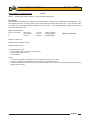
1. Reading data from vehicle
Data Link Connector (DLC) Scan tool
(front of passenger footwell)
Printer
em192a
For instructions on how to use Lotus 3 Scan Tool on a Pre-08MY vehicle to identify Current EMS programs
stored within the ECU or to download new EMS programs and write the correct VIN to the ECU please see
information in section EMP.8.
Page 43
Lotus Service Notes
Section EMP
2. Downloading software from P.C.
With early type adaptor lead
Connect to COM port on PC Adaptor lead used
to connect to
transformer
Power
supply
transformer
em192c
With later type adaptor
Connect to COM port on PC Power supply adaptor
T000T1436F
Power
supply
transformer
em192f
3. Charging printer
Power supply
transformer
Do NOT use adaptor
lead for this application
Printer
Page 44
em192b
Lotus Service Notes
Section EMP
Lotus TechCentre - 2008 model year
All USA market cars from ’08 model year onwards, are required by legislation to use a CAN compliant
on-board diagnostic system. This has been commonised for all Elise/Exige models. The Lotus Scan 3 tool is
replaced by a ‘stand alone’ lap top PC loaded with ‘Lotus TechCentre’ software to allow the CAN based serial
data to be read.
Controller Area Network (CAN) is an electronic standard to allow high speed communication between
modules and controllers, via a serial data bus. The bus is a circuit linking the modules to the controller, consisting of a pair of cables, twisted together to reduce electromagnetic interference, and carrying a square wave
voltage signal corresponding to ‘0’s and ‘1’s, coded in such a way as to identify and prioritise the individual
messages. On the Elise/Exige, CAN based systems for 2008 onwards include; engine management, anti-lock
braking and related features, tyre pressure monitoring and onboard diagnostics.
A Vehicle Communication Device (T000T1472F) introduced for the Europa model is used to connect the
vehicle to the laptop Lotus TechCentre. All system interrogation and diagnosis are carried out via the Lotus
TechCentre.
The minimum specification of the laptop computer for installation of the Lotus TechCentre is as follows:
-
-
-
-
-
-
-
Processer 1.70 Ghz;
1 GB RAM;
40 GB HDD;
CDRW DVD ROM;
WIN XP PRO or VISTA;
USB interface;
Ethernet or Wireless LAN
Note that this laptop should be dedicated soley to the Lotus TechCentre, with no other software installed.
This diagnostic software is designed primarily for use by trained Lotus technicians, and is available as a CD
under part number T000T1510F (version 4) or later supercessions. A monthly (Lotus Dealers) or annual (nonLotus dealers) licence and support fee will also be levied, providing access to Lotus TechCentre Technical
Support phoneline on 0870 9493 668, and e-mail on [email protected]
Also required is a unique 18 character licence/registration key without which Techcentre will not function.
This key is non transferable to other PC’s.
Scope of Lotus TechCentre
Model
Elise
Exige
Europa
2-11
Evora
Esprit
2004 on
2004 on
2006 on
2007 on
2009 on
V8
Type of Electronic Control Unit
Communication compatible
EMS
ABS
SRS
TPMS
Y
Y
Y
Y
Y
Y
Y
Y
N
Y
Y
N/A
Y
Y
N/A
N/A
Y
Y
Y
Y
Y
Y
N
N
IP
N
N
N
N
Y
N
Engine ECU
Reprogrammable
08 MY on
Y
Y
N
Y
Y
N
Note that TechCentre has no connectivity to Rover powertrain Elise/Exige variants, and that only limited
diagnostics are available for the V8 Esprit. No communication is available with the Europa powertrain. Diagnostics for these vehicles are accessible using the Lotus Scan 3 tool T000T1467F (U.K./EU).
For instructions on how to use Lotus TechCentre please see the users guide which can be found on the
Lotus Dealer Portal http://dealers>Aftersales>TechCentre>TechCentre Information.
Page 45
Page 46
Lotus Service Notes
Section EMP
Lotus Service Notes
Section EMP
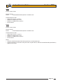
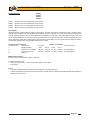
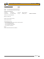
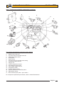
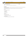
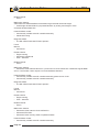
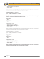
EMP.3 - ENGINE MANAGEMENT COMPONENT LOCATION
1
2
4
3
5
6
17
16
8
15
9
14
13
12
11
10
Key to engine management component location drawing
1. Electronic Control Unit (ECU).
2. Multi-function relay unit.
3. Oil control valve for variable valve lift.
4. Camshaft position sensor.
5. Fuel injector.
6. Knock sensor.
7. Oil control valve for variable valve timing.
8. Crankshaft position sensor.
9. Plug top coil.
10. Coolant temperature sensor.
11. Pre-catalyst oxygen sensor.
12. Post-catalyst oxygen sensor.
13. Oil pressure switch.
14. Throttle position sensor.
15. Vacuum solenoid for intake flap valve.
16. Mass airflow sensor.
17. Idle Air Control (IAC) valve - prior '06 M.Y.
For component replacement procedures, refer to manual B120T0327J.
Page 47
7
Lotus Service Notes
Section EMP
EMP.4 - MECHANICAL THROTTLE SETTING PROCEDURE (Prior '06 M.Y.)
To avoid throttle cable strain, and ensure correct idle control and pedal operation, the following adjustments
must be maintained. If the pedal downstop is incorrectly set, overloading of the throttle body cable quadrant
can occur, resulting in quadrant distortion, closed throttle position error and engine stalling:
1.
Check the throttle body cable quadrant for distortion and mis-alignment. If necessary, repair or replace
the quadrant.
2.
Check that there is 2 - 3 mm free play at the throttle pedal, adjusting at the throttle body cable abutment
bracket if necessary.
3.
If an idle control problem has been reported, reset the closed throttle stop screw on the throttle body:
With ignition off, use a hexagonal key in the bottom end of the throttle stop screw to allow the throttle butterfly valve to fully close, and introduce clearance between the screw and quadrant stop bracket. Screw
upwards until contact is just made, and then a further ½ turn upwards. Secure with the locknut. Recheck
cable adjustment as above.
4.
Adjust the throttle pedal downstop such that vigorous full depression of the pedal achieves full opening of
the throttle butterfly without allowing the cable or mechanism to be strained.
5.
If the throttle stop screw was adjusted, allow the engine to idle for 15 minutes to relearn settings.
6.
An alternative pedal position which may be preferred for 'heel and toeing', may be achieved by replacing
the rubber upstop buffer with an M5x15 hex. head setscrew, with three flat washers beneath the head for
a total thickness of around 7mm. The cable must then be re-adjusted at the engine abutment as above.
The foopad downstop bolt should then be replaced by an M8x20 setscrew and reset as above.
Throttle cable
Closed throttle
stop bracket
Cable quadrant
Throttle stop screw
Page 48
sb77
Lotus Service Notes
Section EMP
emp.5 - 2006 model year electronic throttle control (ETC)
For '06 model year, the 2ZZ-GE engine is equipped with an electronic 'drive by wire' throttle in order to
meet Low Emissions Vehicle 2 emissions standards as dictated by California Air Resources Board. This is
achieved by allowing fuel pre-scheduling and consistency of load demand.
The mechanical throttle control cable is replaced by a pedal actuated potentiometer unit which feeds
pedal movement and position information to the engine management ECU. The ECU compares this demand
information with existing engine throttle position data, and outputs a suitable command signal to the DC stepper motor which operates the throttle valve. For optimum safety, two output curves are produced by the pedal
unit and are fed into two processors contained within the ECU. Similarly, two streams of engine throttle valve
positional information are fed back into these processors, which are then compared by the ECU software. Any
discrepancies are analysed and appropriate safety oriented commands outputed to the throttle valve which may
be limited to a maximum 15% opening, or to a 7% mechanically sprung setting for 'limp home', or in extreme
cases, the injectors may be shut off.
Note that no IAC valve is required, as the idle air control function is incorporated into the electronic throttle system.
ECU Communication
2006 model year cars with ETC have the VIN included in the ECU memory, without which the MIL will
be illuminated, and a fault code stored. The Lotus Scan tool requires an updated operating programme which
includes VIN download facility and is available on CD under part number T000T1466/2. This programme must
be downloaded on to a PC before being transferred to the Scan tool. The ECU progamme is also specific to
ETC, with an i.d. of A120E0030H (non USA) or A121E0010H (USA) .
Page 49
Lotus Service Notes
Section EMP
EMP.6 - DIAGNOSTIC CODE SUPPLEMENT - '06 M.Y.
New fault codes for '06 M.Y. cars with electronic throttle control are as follows:
DTC
Fault Description
P0016 Crankshaft Position – Camshaft Position Correlation Error
(P0121/P0122/P0123 Throttle Position Sensor 'A' - see page 12)
P0222 Throttle Position Sensor 'B' Circuit Low
P0223 Throttle Position Sensor 'B' Circuit High
P0630 VIN Not Programmed or Incompatible – ECU
P0638 Throttle Actuator Control Range/Performance
P2100 Throttle Actuator Control Motor Circuit/Open
P2102 Throttle Actuator Control Motor Circuit/Low
P2103 Throttle Actuator Control Motor Circuit/High
P2104 Throttle Actuator Control System – Forced Idle
P2105 Throttle Actuator Control System – Forced Engine Shutdown
P2106 Throttle Actuator Control System – Forced Limited Power
P2107 Throttle Actuator Control Module Processor
P2108 Throttle Actuator Control Module Performance
P2122 Pedal Position Sensor 'D' Circuit Low
P2123 Pedal Position Sensor 'D' Circuit High
P2127 Pedal Position Sensor 'E' Circuit Low
P2128 Pedal Position Sensor 'E' Circuit High
P2135 Throttle Position Sensor 'A'/'B' Voltage Correlation
P2138 Pedal Position Sensor 'D'/'E' Voltage Correlation P2173 Throttle Actuator Control System – High Airflow Detected
Page 50
Page
49
49
49
50
50
51
51
51
51
52
52
52
53
53
53
54
54
54
55
55
Lotus Service Notes
Crankshaft Position–Camshaft Position Correlation Error
Section EMP
P0016
Description
The crankshaft position sensor is used to identify engine position and speed via a pole wheel mounted on the
front end of the crankshaft. The camshaft position sensor is used to determine camshaft position from a three
vane reluctor on the rear end of the inlet camshaft. The Variable Valve Timing system (VVT) on the inlet camshaft can vary the timing by up to 25°, with fault codes P0011 and P0012 allocated to errors with the variable
timing. Fault code P0016 indicates a mechanical timing error such as incorrectly set, or 'jumped' cam timing.
Enable Criteria:
# Engine running (for up to 4 seconds)
Disable Criteria: None
Potential failure modes:
# Crankshaft/Camshaft alignment
Throttle Position Sensor 'B' Circuit Low
P0222
Description
Two potentiometers are built into the throttle valve actuator unit in order to provide a throttle position signal to
the ECU. Note that the sensors operate on 5 volts.
Enable Criteria: None
Disable Criteria: None
Potential failure modes:
# Signal short circuit (< 0.283 V)
# Reference voltage open circuit
# Reference voltage short to ground
# Sensor failure
Notes: A maximum throttle opening of 15% may be imposed due to this single code. In the case of multiple
codes, a mechanically sprung 7% opening may be applied.
Throttle Position Sensor 'B' Circuit High
P0223
Enable Criteria: None
Disable Criteria: None
Potential failure modes:
# Signal open circuit (> 4.487 V)
# Reference voltage open circuit
# Reference voltage short to ground
# Sensor failure
Notes: A maximum throttle opening of 15% may be imposed due to this single code. In the case of multiple
codes, a mechanically sprung 7% opening may be applied.
Page 51
Lotus Service Notes
VIN Not Programmed or Incompatible – ECU/PCM Section EMP
P0630
Description
The ECM programming includes the Vehicle Identification Number (VIN). This operation is performed using
the Lotus Scan tool.
Enable Criteria:
# Engine running (for up to 4 seconds)
Disable Criteria: None
Potential failure modes:
# VIN not programmed
# Incompatible VIN programmed
Throttle Actuator Control Range/Performance
P0638
Description
The single throttle butterfly valve, mounted at the inlet to the intake plenum, is operated by a stepper motor
under the command of the engine ECU. The valve moves through a range of nearly 90° and should display
100% at full throttle and around 2% at idle.
Monitor: Continuous
Enable Criteria:
# Engine running
Disable Criteria:
# Electronic throttle fault(s) present
Potential failure modes:
# Blocked throttle body
# Damage to throttle actuator
Notes: A mechanically sprung 7% throttle opening may be imposed.
Page 52
Lotus Service Notes
Throttle Actuator Control Motor Circuit/Open
Section EMP
P2100
Description
The throttle actuator stepper motor operates on 12 volts.
Monitor: Continuous
Enable Criteria: None
Disable Criteria: None
Potential failure modes:
#Throttle actuator control motor open circuit
Throttle Actuator Control Motor Circuit/Low
P2102
Monitor: Continuous
Enable Criteria: None
Disable Criteria: None
Potential failure modes:
# Throttle actuator control motor short to ground
Throttle Actuator Control Motor Circuit/High
P2103
Monitor: Continuous
Enable Criteria: None
Disable Criteria: None
Potential failure modes:
# Throttle actuator control motor short to supply voltage
Throttle Actuator Control System – Forced Idle
P2104
Description
If a problem is detected which could result in faster engine speed than commanded by the pedal, the actuator
is switched out, allowing the throttle valve to default to a 6% mechanically sprung setting. This provides a fast
idle speed which may be used to effect a 'limp home' mechanism.
Monitor: Continuous
Enable Criteria: Engine running
Disable Criteria: None
Potential failure modes:
# Electronic throttle fault
Note: This code indicates action taken by the ECU, and will always be accompanied by another code which
has caused this action.
Page 53
Lotus Service Notes
Throttle Actuator Control System – Forced Engine Shutdown
Section EMP
P2105
Description
If a problem is detected which could result in engine speed runaway, or if sufficient control of engine speed is
lost, the ECU switches off the fuel injectors in order to stop the engine.
Monitor: Continuous
Enable Criteria: Engine running
Disable Criteria: None
Potential failure modes:
# Electronic throttle fault
Note: This code indicates action taken by the ECU, and will always be accompanied by another code which
has caused this action.
Throttle Actuator Control System – Forced Limited Power
P2106
Description
If a problem is detected which could result in engine speed control difficulties, the ECU will limit throttle opening
to a maximum of 15%.
Monitor: Continuous
Enable Criteria: Engine running
Disable Criteria: None
Potential failure modes:
# Electronic throttle fault
Note: This code indicates action taken by the ECU, and will always be accompanied by another code which
has caused this action.
Throttle Actuator Control Module Processor P2107
Description
The ECU contains two processors dedicated to the throttle pedal and throttle valve potentiometers.
Monitor: Continuous
Enable Criteria: Engine running
Disable Criteria: None
Potential failure modes:
# ECU internal fault
# Incorrect ECU programming
Page 54
Lotus Service Notes
Throttle Actuator Control Module Performance
Section EMP
P2108
Monitor: Continuous
Enable Criteria: Engine running
Disable Criteria: None
Potential failure modes:
# ECU internal failure
# Short circuit to throttle actuator
Pedal Position Sensor 'D' Circuit Low
P2122
Description
Two potentiometers are built into the throttle pedal unit in order to provide a throttle demand signal to the ECU.
Note that the potentiometers operate on 5 volts.
Enable Criteria: None
Disable Criteria: None
Potential failure modes:
# Signal short circuit (< 0.283 V)
# Reference voltage open circuit
# Reference voltage short to ground
# Sensor failure
Notes: A maximum throttle opening of 15% may be imposed due to this single code. In the case of multiple
codes, a mechanically sprung 7% opening may be applied.
Pedal Position Sensor 'D' Circuit High P2123
Enable Criteria: None
Disable Criteria: None
Potential failure modes:
# Signal open circuit (> 4.487 V)
# Reference voltage open circuit
# Reference voltage short to ground
# Sensor failure
Notes: A maximum throttle opening of 15% may be imposed due to this single code. In the case of multiple
codes, a mechanically sprung 7% opening may be applied.
Page 55
Lotus Service Notes
Pedal Position Sensor 'E' Circuit Low
Section EMP
P2127
Description
Two potentiometers are built into the throttle pedal unit in order to provide a throttle demand signal to the ECU.
Note that the potentiometers operate on 5 volts.
Enable Criteria: None
Disable Criteria: None
Potential failure modes:
# Signal short circuit (< 0.283 V)
# Reference voltage open circuit
# Reference voltage short to ground
# Sensor failure
Notes: A maximum throttle opening of 15% may be imposed due to this single code. In the case of multiple
codes, a mechanically sprung 7% opening may be applied.
Pedal Position Sensor 'E' Circuit High
P2128
Enable Criteria: None
Disable Criteria: None
Potential failure modes:
# Signal open circuit (> 4.487 V)
# Reference voltage open circuit
# Reference voltage short to ground
# Sensor failure
Notes: A maximum throttle opening of 15% may be imposed due to this single code. In the case of multiple
codes, a mechanically sprung 7% opening may be applied.
Throttle Position Sensor 'A'/'B' Voltage Correlation
P2135
Description
Two potentiometers are built into the throttle actuator unit in order to provide a throttle position signal to the
ECU. Two processors within the ECU compare the two output signals, which should match within a defined
tolerance. Note that the potentiometers operate on 5 volts.
Enable Criteria: None
Disable Criteria: Throttle position greater than 60%
Potential failure modes:
# TPS1 reading incorrectly
# TPS2 reading incorrectly
Notes: A maximum throttle opening of 15% may be imposed.
Page 56
Lotus Service Notes
Pedal Position Sensor/Switch 'D'/'E' Voltage Correlation Section EMP
P2138
Description
Two potentiometers are built into the throttle pedal unit in order to provide a throttle demand signal to the ECU.
Two processors within the ECU compare the two output signals, which should match within a defined tolerance.
Note that the potentiometers operate on 5 volts.
Enable Criteria: None
Disable Criteria: None
Potential failure modes:
# PPS1 reading incorrectly
# PPS2 reading incorrectly
Notes: A maximum throttle opening of 15% may be imposed.
Throttle Actuator Control System – High Airflow Detected
P2173
Description
The mass air flow is compared with the throttle position to determine whether an incorrect correlation exists.
Enable Criteria: None
Disable Criteria: MAF fault(s) present
Potential failure modes:
# Throttle plate damage
# Air leak in intake system
Notes: A mechanically sprung 7% throttle opening may be imposed, or the injectors may be shut off to stop
the engine.
Page 57
Lotus Service Notes
Section EMP
EMP.7 - DIAGNOSTIC CODE SUPPLEMENT - 2011 M.Y. ELISE 1ZR POWERTRAIN (Euro 5)
DTC
Fault Description
P0011 "A" Camshaft Position - Timing Over-Advanced or System Performance
P0012 "A" Camshaft Position - Timing Over-Retarded P0014 "B" Camshaft Position - Timing Over-Advanced or System Performance P0015 "B" Camshaft Position - Timing Over-Retarded
P0016 Crankshaft Position - Camshaft Position Correlation, Sensor A
P0017 Crankshaft Position - Camshaft Position Correlation, Sensor B
P0076 Intake Valve Control Solenoid Circuit Low P0077 Intake Valve Control Solenoid Circuit High
P0079 Exhaust Valve Control Solenoid Circuit Low P0080 Exhaust Valve Control Solenoid Circuit High
P0101 Mass or Volume Air Flow Circuit Range/Performance Problem
P0102 Mass or Volume Air Flow Circuit Low Input
P0103 Mass or Volume Air Flow Circuit High Input
P0107 Manifold Absolute Pressure/Barometric Pressure Circuit Low Input
P0108 Manifold Absolute Pressure/Barometric Pressure Circuit High Input
P0112 Intake Air Temperature Circuit Low Input
P0113 Intake Air Temperature Circuit High Input
P0116 Engine Coolant Temperature Circuit Range/Performance Problem
P0117 Engine Coolant Temperature Circuit Low Input
P0118 Engine Coolant Temperature Circuit High Input
P0122 Throttle/Pedal Position Sensor/Switch A Circuit Low Input
P0123 Throttle/Pedal Position Sensor/Switch A Circuit High Input
P0131 O2 Sensor Circuit Low Voltage (Sensor 1)
P0132 O2 Sensor Circuit High Voltage (Sensor 1)
P0133 O2 Sensor Circuit Slow Response (Sensor 1)
P0134 O2 Sensor Circuit No Activity Detected (Sensor 1)
P0135 O2 Sensor Heater Circuit (Sensor 1)
P0137 O2 Sensor Circuit Low Voltage (Sensor 2)
P0138 O2 Sensor Circuit High Voltage (Sensor 2)
P0139 O2 Sensor Circuit Slow Response (Sensor 2)
P0140 O2 Sensor Circuit No Activity Detected (Sensor 2)
P0141 O2 Sensor Heater Circuit (Sensor 2)
P0171 System too Lean P0172 System too Rich P0222 Throttle/Pedal Position Sensor/Switch "B" Circuit Low Input
P0223 Throttle/Pedal Position Sensor/Switch "B" Circuit High Input
P0261 Cylinder 1 Injector Circuit Low
P0262 Cylinder 1 Injector Circuit High
P0264 Cylinder 2 Injector Circuit Low
P0265 Cylinder 2 Injector Circuit High
P0267 Cylinder 3 Injector Circuit Low
P0268 Cylinder 3 Injector Circuit High
P0270 Cylinder 4 Injector Circuit Low
P0271 Cylinder 4 Injector Circuit High
P0300 Random/Multiple Cylinder Misfire Detected
P0301 Cylinder 1 Misfire Detected
P0302 Cylinder 2 Misfire Detected
P0303 Cylinder 3 Misfire Detected
P0304 Cylinder 4 Misfire Detected
P0327 Knock Sensor 1 Circuit Low Input
P0328 Knock Sensor 1 Circuit High Input
P0335 Crankshaft Position Sensor A Circuit
Page 58
Page
61
61
61
61
62
62
63
63
63
63
64
65
65
66
66
67
67
69
70
70
71
72
74
75
75
76
76
77
78
78
79
80
81
81
72
72
83
83
83
83
83
83
83
83
84
84
84
84
84
86
86
87
DTC
P0341
P0351
P0352
P0353
P0354
P0366
P0420
P0444
P0445
P0462
P0463
P0480
P0481
P0500
P0506
P0507
P0537
P0538
P0562
P0563
P0565
P0567
P0568
P0571
P0601
P0606
P0610
P0617
P0628
P0629
P0630
P0638
P0661
P0662
P0685
P0703
P0806
P0807
P0808
P1045
P1046
P1047
P1049
P1055
P1107
P1108
P1301
P1302
P1645
P2100
P2102
P2103
P2104
P2105
P2106
Lotus Service Notes
Section EMP
Fault Description
Page
Camshaft Position Sensor "A" Circuit Range/Performance 88
Ignition Coil "A" Primary/Secondary Circuit 89
Ignition Coil "B" Primary/Secondary Circuit 89
Ignition Coil "C" Primary/Secondary Circuit 89
Ignition Coil "D" Primary/Secondary Circuit 89
Camshaft Position Sensor "B" Circuit Range/Performance 88
Catalyst System Efficiency Below Threshold) 90
Evaporative Emission Control System Purge Control Valve Circuit Open 91
Evaporative Emission Control System Purge Control Valve Circuit Shorted 91
Fuel Level Sensor Circuit Low Input 92
Fuel Level Sensor Circuit High Input 92
Cooling Fan 1 Control Circuit 93
Cooling Fan 2 Control Circuit 93
Vehicle Speed Sensor 94
Idle Control System RPM Lower Than Expected 95
Idle Control System RPM Higher Than Expected95
A/C Evaporator Temperature Sensor Circuit Low 96
A/C Evaporator Temperature Sensor Circuit High 96
System Voltage Low 97
System Voltage High 97
Cruise control on/off signal 98
Cruise control resume/decel signal 98
Cruise control set/accel signal 98
Cruise Control/Brake Switch A Circuit 99
Internal Control Module Memory Check Sum Error
100
ECM/PCM Processor
100
Control Module Vehicle Options Error
101
Starter Relay Circuit High
102
Fuel Pump "A" Control Circuit Low
103
Fuel Pump "A" Control Circuit High
103
VIN Not Programmed or Mismatch - ECM/PCM
104
Throttle Actuator Control Range/Performance
105
Intake Manifold Tuning Valve Control Circuit Low
106
Intake Manifold Tuning Valve Control Circuit High
106
ECM/PCM Power Relay Control Circuit/Open
107
Brake Switch "B" Circuit
107
Clutch Position Sensor Circuit Range/Performance
108
Clutch Position Sensor Circuit Low
108
Clutch Position Sensor Circuit High
108
Valvematic SDOWN Circuit Malfunction
110
Valvematic ECU Detected Difference Between Target and Actual Valvematic Angle
110
Valvematic Driver Learned Value Error / Power Source Circuit Malfunction
111
Valvematic Driver Internal Circuit Malfunction
111
ECU Detected Difference Between Target and Actual Valvematic Angle
112
Manifold Absolute Pressure Circuit Low Input
115
Manifold Absolute Pressure Circuit High Input
115
Misfire level causing emissions increase
116
Misfire level causing catalyst system damage
116
112
VM Actuator Position sensor circuit Throttle Actuator Circuit/Open
117
Throttle Actuator Control Motor Circuit Low
118
Throttle Actuator Control Motor Circuit High
119
Throttle Actuator Control System - Forced Idle
120
Throttle Actuator Control System - Forced Engine Shutdown
120
Throttle Actuator Control System - Forced Limited Power
121
Page 59
Lotus Service Notes
Section EMP
DTC Fault Description
P2107 Throttle Actuator Control Module Processor
P2108 Throttle Actuator Control Module Performance
P2119 Throttle Actuator Control Throttle Body Range/Performance
P2122 Pedal Position Sensor 1 Low Input
P2123 Pedal Position Sensor 1 Hi Input
P2127 Pedal Position Sensor 2 Low Input
P2128 Pedal Position Sensor 2 Hi Input
P2135 Throttle Position Sensors Correlation
P2138 Pedal Position Sensors Correlation
P2173 Throttle Actuator Control System - High Airflow Detected
P2612 A/C Refrigerant Distribution Valve Control Circuit Low
P2613 A/C Refrigerant Distribution Valve Control Circuit High
P2646 “A” Rocker Arm Actuator System Performance or Stuck Off
P2647 “A” Rocker Arm Actuator System Stuck On
P2648 “A” Rocker Arm Actuator Control Circuit Low
P2649 “A” Rocker Arm Actuator Control Circuit High
U0101 Lost communications with TCM
U0115 Lost communication with ECM/PCM “B” (Valvematic controller)
U0122 Lost Communications with VDCM U0316 Software Incompatible with VDCM Page
122
123
124
125
125
126
126
127
128
129
130
130
112
113
113
114
131
131
132
132
Note; Fault code P1047
If the power supply to the VALVEMATIC controller is lost during normal vehicle operation, code P1047 will
be stored and a limphome mode initiated. This will result in limited engine torque being available for the remainder
of the ignition cycle. Re-instatement of the power supply will not automatically eradicate the code, and neither
will clearing of the code via Lotus TechCentre be effective until a learing process has been completed.
After rectification of the power supply fault, proceed as follows:
1.
Ignition off and allow ECU to power down (wait for 30 seconds).
2.
Start engine and allow to idle for 30 seconds. Idle speed may increase during this recovery process.
3.
Ignition off for 30 seconds.
4.
Start engine and allow to idle for 30 seconds.
5.
Ignition off for 30 seconds.
6.
Ignition on and use Lotus TechCentre to reset code P1047 (and any other VALVEMATIC related fault
codes).
Process complete.
Page 60
Lotus Service Notes
Section EMP
Camshaft Timing Control (VVT) P0011
P0012
P0014
P0015
P0011 Camshaft Position – Inlet Timing Over-Advanced or System Performance
P0012 Camshaft Position – Inlet Timing Over-Retarded
P0014 Camshaft Position – Exhaust Timing Over-Advanced or System Performance
P0015 Camshaft Position – Exhaust Timing Over Retarded
Description
The Variable Valve Timing system (VVT) on the intake camshafts and the exhaust camshafts can vary the timing
by approximately 35° on exhaust and 53° on inlet. The camshaft relative position is varied by a system
of vanes mounted on the drive end of the camshaft. Each VVT oil control valve modulates a spool valve
position in accordance with the drive signal duty cycle, this in turns controls the oil pressure applied to the
vanes. A 50% duty cycle applied to the valve will hold the valve current timing by preventing oil flow from
the VVT controller housing, a duty cycle less than 50% will retard the valve timing, a duty cycle greater
then 50% will advance the valve timing. The ECM regulates this duty cycle based on the feedback signal
from the respective camshaft position sensor to optimise the camshaft timing.
Component connections
Sensor Connector Description
1 Battery Voltage
2 VVT Control ValveInlet 1
2
ECU Pin ECU Connector
- B2
48 Way (Centre)
Battery Voltage
VVT Control Valve Exhaust - A2
48 Way (Centre)
P0011, P0012. P0014. P0015.
Monitor:
•
Continuous
Enable Criteria:
•
Engine running > 30 secs
•
Coolant temperature > 60°C (140°F)
Disable Criteria:
•
P0116, P0117, P0118 – Coolant temperature fault codes
Malfunction Criteria:
•
VVT error > 5 degrees for time > 2.5 secs
Potential failure modes:
•
Static valve timing is incorrect
•
VVT camshaft actuator failure
•
VVT control valve stuck open / closed
•
VVT control valve filter
Diagnostic Mask:
•
The MIL will be illuminated if the faults are present for 2 consecutive trips
Page 61
Lotus Service Notes
Crankshaft Position–Camshaft Position Correlation Error
P0016
P0017
Section EMP
P0016
P0017
Crankshaft position – camshaft position correlation – bank 1 sensor A (Inlet)
Crankshaft position – camshaft position correlation – bank 1 sensor B (Exhaust)
Description
The crankshaft position sensor is used to identify engine position and speed via a pole wheel mounted on the
front end of the crankshaft. The camshaft position sensor is used to determine camshaft position from a
three vane reluctor on the rear end of the inlet and exhaust camshaft. Fault codes P0016, P0017, indicate
a mechanical timing error such as incorrectly set, or 'jumped' cam timing.
Monitor:
•
Continuous
Enable Criteria:
•
Engine running (from cranking up to 4 seconds)
Disable Criteria:
•
None
Malfunction Criteria:
•
Camshaft out of phase with crankshaft > 16 degrees
Potential failure modes:
•
Static valve timing is incorrect
•
VVT camshaft actuator failure
•
VVT control valve stuck open / closed
•
VVT control valve filter
Diagnostic Mask:
•
The MIL will be illuminated if the faults are present for 2 consecutive trips
Page 62
Lotus Service Notes
Camshaft Timing Control (VVT)
P0076
P0077
P0079
P0080
Section EMP
P0076
P0077
P0079
P0080
Intake Valve Control Solenoid Circuit Low
Intake Valve Control Solenoid Circuit High
Exhaust Valve Control Solenoid Circuit Low
Exhaust Valve Control Solenoid Circuit High
P0076, P0077, P0079, P0080,
Monitor:
•
Continuous
Enable Criteria:
•
Engine running
Disable Criteria:
•
None
Potential failure modes:
•
P0076, P0079, - VVT control valve open circuit or short to ground
•
P0077, P0080, - VVT control valve circuit short to battery voltage
•
ECU output circuit failure
•
VVT control valve
Diagnostic Mask:
•
The MIL will be illuminated if the faults are present for 2 consecutive trips
Page 63
Lotus Service Notes
Intake Air Flow
P0101
P0102
P0103
Section EMP
P0101
P0102
P0103
Mass or Volume Air Flow Circuit Range/Performance
Mass or Volume Air Flow Circuit Low Input
Mass or Volume Air Flow Circuit High Input
Description
The Mass Air Flow (MAF) sensor is incorporated into the airbox, and measures both intake air flow rate and
Intake Air Temperature (IAT). The MAF sensor uses a hot wire exposed to the airflow, which is maintained
at a constant temperature by a constant current flow. This is achieved within the sensor unit by varying
the voltage applied to the hot wire. This voltage is the output signal from the MAF sensor.
Sensor connections
Sensor Connector Description ECU Pin ECU Connector
1 IAT Signal E3 48 Way (Centre)
2 IAT Ground J3 48 Way (Centre)
3 Battery Voltage - 4 MAF Ground J4 48 Way (Centre)
5 MAF Signal G1 48 Way (Centre)
Sensor characteristics
0 – 330 g/sec
Typical values: 1.5 – 5.5 g/sec (idle), 5.0 – 15.0 g/sec (2500rpm elevated idle no load)
P0101
Monitor:
•
Continuous.
Enable Criteria:
•
Engine running
•
Engine speed >1500rpm
•
Engine speed < 3510rpm
•
Fuel Learns enabled
Disable Criteria:
•
P0122, P0123, P0222, P0223 – Throttle/Pedal position fault codes
Malfunction Criteria:
•
Measured MAF is compared to a predicted MAF based on current engine conditions.
•
Error > 40% for time > 1.5 secs
Potential failure modes:
•
MAF meter
•
Air induction system
•
Air intake hose connections
Diagnostic Mask:
•
The MIL will be illuminated if the faults are present for 2 consecutive trips
Page 64
Lotus Service Notes
P0102
Monitor:
• Continuous.
Enable Criteria:
• Engine running
Disable Criteria:
• None
Malfunction Criteria:
• Voltage at ECU < 0.52V for time > 1.5 secs
Potential failure modes:
• MAF sensor circuit open
• MAF sensor circuit short to ground
Diagnostic Mask:
• The MIL will be illuminated if the faults are present for 2 consecutive trips
P0103
Monitor:
• Continuous.
Enable Criteria:
• Engine running
Disable Criteria:
• None
Malfunction Criteria:
• Voltage at ECU > 4.86V for time > 1.5 secs
Potential failure modes:
• MAF sensor circuit short to ECU supply voltage
Diagnostic Mask:
• The MIL will be illuminated if the faults are present for 2 consecutive trips
Page 65
Section EMP
Lotus Service Notes
Barometric Pressure
P0107
P0108
Section EMP
P0107
P0108
Manifold Absolute Pressure/Barometric Pressure Circuit Low Input
Manifold Absolute Pressure/Barometric Pressure Circuit High Input
Description
The barometric pressure sensor is located internally within the ECU, and measures atmospheric pressure.
This parameter is required to compensate the mass air flow when the vehicle is operated at higher altitudes.
P0107, P0108
Monitor:
• Continuous
Enable Criteria:
• Engine running
Disable Criteria:
• None
Malfunction Criteria:
• P0107: Voltage at ECU < 1.08V for time > 1.5 secs
• P0108: Voltage at ECU > 4.98V for time > 1.5 secs
Potential failure modes:
• Sensor failure
Diagnostic Mask:
• The MIL will be illuminated if the faults are present for 2 consecutive trips
Page 66
Lotus Service Notes
Intake Air Temperature
Section EMP
P0112
P0113
P0112 Intake Air Temperature Sensor 1 Circuit Low
P0113 Intake Air Temperature Sensor 1 Circuit High
Description
The combined sensor which measures both Mass Air Flow (MAF) and Intake Air Temperature (IAT) is
incorporated into the air box. The IAT sensor is a thermistor device which changes resistance with temperature. As air intake temperature decreases the thermistor resistance value increases, and conversely as air
temperature increases so the thermistor resistance value decreases.
Sensor connections
Sensor Connector
1
2
3
4
5
Description ECU Pin ECU Connector
IAT Signal E3 48 Way (Centre)
IAT Ground J3 48 Way (Centre)
Battery Voltage - MAF Ground J4 48 Way (Centre)
MAF Signal G1 48 Way (Centre)
Sensor characteristics
IAT -20°C (-4°F) 13.6 – 18.4 kΩ
IAT 20°C (68°F) 2.21 – 2.69 kΩ
IAT 60°C (140°F) 0.50 – 0.67 kΩ
P0112
Monitor:
• Continuous
Disable Criteria:
• None
Enable Criteria:
• Engine running
Malfunction Criteria:
• Inlet air temperature > 119°C (246°F) for time > 1.5 secs
Potential failure modes:
• Signal short circuit
• Sensor failure
Diagnostic Mask:
• The MIL will be illuminated if these faults are present for 2 consecutive trips.
P0113
Monitor:
• Continuous
Disable Criteria:
• None
Page 67
Lotus Service Notes
Section EMP
Enable Criteria:
• Engine running
Malfunction Criteria:
• Inlet air temperature < –40°C (–40°F) for time > 1.5 secs
Potential failure modes:
• Signal open circuit
• Sensor failure
Diagnostic Mask:
• The MIL will be illuminated if these faults are present for 2 consecutive trips.
Page 68
Lotus Service Notes
Engine Coolant Temperature
P0116
P0117
P0118
Section EMP
P0116
P0117
P0118
Engine Coolant Temperature Circuit Range/Performance
Engine Coolant Temperature Circuit Low
Engine Coolant Temperature Circuit High
Description
The engine coolant temperature sensor is a thermistor device which changes resistance with temperature. As coolant temperature decreases the thermistor resistance value increases, and conversely as coolant
temperature increases so the thermistor resistance value decreases.
Sensor connections
Sensor Connector
1
2
Description
Ground
Signal
ECU Pin
C3
G2 Sensor characteristics
-20°C (-4°F) = 13.75 – 16.25 KΩ 20°C (68°F) = 2.31 – 2.58 KΩ 80°C (176°F) = 0.310 – 0.326 KΩ 110°C (230°F) = 0.1375 – 0.1425 KΩ
ECU Connector
48 Way (Centre)
48 Way (Centre)
(15KΩ)
(2.45KΩ)
(320Ω)
(140Ω)
P0116
Monitor:
• Continuous
Disable Criteria:
• None
Enable Criteria 1:
• Engine running > 1000 seconds
Malfunction Criteria 1:
• Engine coolant temperature < 40°C (104°F)
Enable Criteria 2:
• Engine running
Malfunction Criteria 2:
• Engine coolant temperature erratic by more than 30°C (54°F)
Potential failure modes:
• Sensor wiring
• Sensor failure
• Thermostat failure
Diagnostic Mask:
• The MIL will be illuminated if these faults are present for 2 consecutive trips.
Page 69
Lotus Service Notes
Section EMP
P0117
Monitor:
• Continuous
Disable Criteria:
• None
Enable Criteria:
• Engine running
Malfunction Criteria:
• Coolant temperature > 119°C (246°F) for time > 1.5 secs
Potential failure modes:
• Signal short circuit
• Sensor failure
• Thermostat failure
• Cooling system problem
Diagnostic Mask:
• The MIL will be illuminated if these faults are present for 2 consecutive trips.
P0118
Monitor:
• Continuous
Disable Criteria:
• None
Enable Criteria:
• Engine running
Malfunction Criteria:
• Coolant temperature > -38°C (-36°F) for time > 1.5 secs
Potential failure modes:
• Signal open circuit
• Sensor failure
Diagnostic Mask:
• The MIL will be illuminated if these faults are present for 2 consecutive trips.
Page 70
Lotus Service Notes
Throttle Position
Section EMP
P0122
P0123
P0222
P0223
P0122 Throttle Position Sensor 'A' Circuit Low
P0123 Throttle Position Sensor 'A' Circuit High
P0222 Throttle Position Sensor ‘B’ Circuit Low
P0223 Throttle Position Sensor ‘B’ Circuit High
Description
The throttle position sensor (TPS) is mounted on the throttle body, and detects the opening angle of the
throttle valve. The TPS has 2 sensor circuits, each of which transmits a signal, VTA1 and VTA2. VTA1 is used
to detect the throttle valve angle and VTA2 is used to detect malfunctions in VTA1. The sensor signal voltages
vary between 0 V and 5 V in proportion to the throttle valve opening angle, and are transmitted to the VTA
terminals of the ECU.
Sensor connections
Sensor Connector
1 2 3
4
5
6
Description ECU Pin
ETB +ve M1 ETB +-ve L2 Ground
C4
TPS 1B Signal F3 TPS 1A/B V Ref E4
TPS 1A Signal F2
ECU Connector
48 Way (Centre)
48 Way (Centre)
48 Way (Centre)
48 Way (Centre)
48 Way (Centre)
48 Way (Centre)
Sensor characteristics
Sensor 1A
0% = 0.69 V ± 5%
100% = 3.87 V ± 5%
Sensor 1B
0% = 2.25 V ± 5%
100% = 4.94 V ± 5%
Idle state is not 0% throttle position and is dependant upon coolant temperature.
P0122
Monitor:
• Continuous.
Enable Criteria:
• None
Disable Criteria:
• None
Malfunction Criteria:
• Signal voltage < 0.635V
Potential failure modes:
• Signal short circuit
• Reference voltage open circuit
• Reference voltage short to ground
• Sensor failure
Diagnostic Mask:
• The MIL will be illuminated if fault is present.
Page 71
Lotus Service Notes
P0123
Monitor:
• Continuous.
Enable Criteria:
• None
Disable Criteria:
• None
Malfunction Criteria:
• Signal voltage > 4.765V
Potential failure modes:
• Signal open circuit
• Reference voltage open circuit
• Reference voltage short to ground
• Sensor failure
Diagnostic Mask:
• The MIL will be illuminated if fault is present.
P0222
Monitor:
• Continuous.
Enable Criteria:
• None
Disable Criteria:
• None
Malfunction Criteria:
• Signal voltage < 2.146V
Potential failure modes:
• Signal short circuit
• Reference voltage open circuit
• Reference voltage short to ground
• Sensor failure
Diagnostic Mask:
• The MIL will be illuminated if fault is present.
P0223
Monitor:
• Continuous.
Enable Criteria:
• None
Disable Criteria:
• None
Page 72
Section EMP
Lotus Service Notes
Section EMP
Malfunction Criteria:
• Signal voltage > 4.985V
Potential failure modes:
• Signal open circuit
• Reference voltage open circuit
• Reference voltage short to ground
• Sensor failure
Diagnostic Mask:
• The MIL will be illuminated if fault is present.
Notes: A maximum throttle opening of 15% may be imposed due to this single code. In the case of multiple codes, a mechanically sprung 7% opening may be applied.
Page 73
Lotus Service Notes
O2 Sensor (Pre Catalyst)
P0131 O2 Sensor 1 Circuit Low Voltage
P0132 O2 Sensor 1 Circuit High Voltage
P0133 O2 Sensor 1 Circuit Slow Response
P0134 O2 Sensor 1 Circuit No Activity Detected
P0135 O2 Sensor 1 Heater Circuit
Section EMP
P0131
P0135
P0132
P0133
P0134
Description
The oxygen sensors separately monitor the oxygen content in the exhaust gases of each bank of the
engine. Each sensor is electrically heated to improve response after start.
The sensor consists of a zirconia electrode between two platinum plates. When zirconia comes into contact
with oxygen, it becomes an electrical conductor. The exhaust gases pass through louvers in the sensor. One
plate is in contact with the outside air and the other plate is in contact with the exhaust gases. The platinum plate
in contact with the air is electrically negative due to the oxygen in the atmosphere and the plate in contact with
the exhaust gases is electrically positive. This will cause a difference in electrical potential to develop between
the two plates. Thus the voltage across the platinum plates ranges approximately from 100 millivolts to 900
millivolts, depending on the oxygen content of the exhaust gases. Thus when the air/fuel mixture is rich, the
oxygen sensor output will be high. If the air/fuel mixture is lean, the oxygen sensor output will be low.
Sensor connections
Sensor Connector
1 Bank 1
2 Bank 1
3 Bank 1
4 Bank 1
Description
Signal
Ground
Heater Battery Voltage
ECU Pin ECU Connector
G3 48 Way (Centre)
J2 48 Way (Centre)
H3 48 Way (Centre)
-
-
Sensor characteristics
Normal operating range is 0 – 1000mV
P0131
Monitor:
• Continuous.
Disable Criteria:
• DFCO (Deceleration Fuel Cut Off)
• AE DE (Acceleration Enrichment Deceleration Enleanment)
• Misfire
Enable Criteria:
• Engine running
Failure Criteria:
• Sensor voltage < 24mV for more than 1.5 seconds consecutively for a specified number of times.
Potential failure modes:
• Low fuel pressure (Lean mixture)
• Malfunctioning sensor
• External water on sensor
• Sensor wire shorted to ground
Diagnostic Mask:
• The MIL will be illuminated if these faults are present for 2 consecutive trips.
Page 74
Lotus Service Notes
Section EMP
P0132
Monitor:
• Continuous.
Disable Criteria:
• None
Enable Criteria:
• Engine running
Malfunction Criteria:
• Sensor voltage > 1200V for more than 1.5 seconds consecutively for a specified number of times.
Potential failure modes:
• High fuel pressure (Rich mixture)
• Leaking or shorted injector
• Purge valve fault
• Oxygen sensor contamination
• Engine oil contamination
• Sensor wire shorted to heater voltage
Diagnostic Mask:
• The MIL will be illuminated if these faults are present for 2 consecutive trips.
P0133
Monitor:
• Continuous.
Disable Criteria:
• P0116, P0117, P0118 – Coolant temperature sensor faults
• P0101, P0102, P0103 – MAF sensor faults
• P0335, P0500 – Crank or vehicle speed faults
• P0131, P0132, P0134, P0135 – Pre catalyst oxygen sensor faults checks
Enable Criteria:
• Vehicle speed between 0 – 255 km/h (158.5 mph)
• Percentage load between 22 – 70 %
• Engine speed between 1285 – 3511 rpm
• Engine run time > 200 seconds
• Coolant temperature > 60°C (140°F)
• Closed loop fuelling enabled
Monitor:
• Monitored until the required amount of switches (30) in both directions has been achieved or 130 seconds has elapsed.
Malfunction Criteria:
• Set when the sensor fails to switch from a Lean to a Rich condition or switch from a Rich to a Lean condition in a sufficiently timely manner. A selection of switches is used to determine the average times.
Potential failure modes:
• Sensor connector and wiring should be checked for corrosion and loose connections
• Sensor contaminated, possibly from fuel, improper use of RTV, engine oil or coolant
Diagnostic Mask:
• The MIL will be illuminated if these faults are present for 2 consecutive trips.
Page 75
Lotus Service Notes
Section EMP
P0134
Monitor:
• Until either passed or failed.
Enable Criteria:
• Engine run time > 30 seconds
• Engine is not at idle
• Engine is in closed loop fuel control
• O2 sensor ready
Malfunction Criteria:
• Set when the sensor fails to switch above 600mV and below 322mV within a 60 second period.
Potential failure modes:
• Sensor connector and wiring should be checked for corrosion and loose connections.
• Gas leak in exhaust system
Diagnostic Mask:
• The MIL will be illuminated if these faults are present for 2 consecutive trips.
P0135
Monitor:
• Continuous
Enable Criteria:
• Engine run time > 20 seconds
Malfunction Criteria:
• Set when the heater output is greater than 1900mA or less than 250mA for 1.5 seconds, for 40 con-
secutive checks.
Potential failure modes:
• Sensor connector and wiring should be checked for corrosion and loose connections.
Diagnostic Mask:
• The MIL will be illuminated if these faults are present for 2 consecutive trips.
Page 76
Lotus Service Notes
O2 Sensor (Post Catalyst)
P0137 O2 Sensor Circuit Low Voltage
P0138 O2 Sensor Circuit High Voltage
P0139 O2 Sensor Circuit Slow Response
P0140 O2 Sensor Circuit No Activity Detected
P0141 O2 Sensor Heater Circuit
Section EMP
P0137
P0138
P0139
P0140
P0141
Description
The oxygen sensors separately monitor the oxygen content in the exhaust gases of each bank of the
engine. Each sensor is electrically heated to improve response from start.
The sensor consists of a zirconia electrode between two platinum plates. When zirconia comes into
contact with oxygen, it becomes an electrical conductor. The exhaust gases passes through louvers in the
sensor. One plate is in contact with the outside air and the other plate is in contact with the exhaust gases.
The platinum plate in contact with the air is electrically negative due to the oxygen in the atmosphere and the
plate in contact with the exhaust gases is electrically positive. This will cause a difference in electrical potential
to develop between the two plates. Thus the voltage across the platinum plates ranges approximately from
100 millivolts to 900 millivolts, depending on the oxygen content of the exhaust gases. Thus when the air/fuel
mixture is rich, the oxygen sensor output will be high. If the air/fuel mixture is lean, the oxygen sensor output
will be low. The post catalyst oxygen sensor performance is a good indicator of catalyst efficiency.
Sensor connections
Sensor Connector
1 2 3 4 Description
Signal
Ground
Heater Battery Voltage
ECU Pin ECU Connector
H1 48 Way (Centre)
K4 48 Way (Centre)
K2
48 Way (Centre)
-
-
Sensor characteristics
Normal operating range is 0 – 1000mV
Malfunction Criteria
P0137
Monitor:
• Continuous
Enable Criteria:
• None
Disable Criteria:
• DFCO (Deceleration Fuel Cut Off)
• AE DE (Acceleration Enrichment or Deceleration Enleanment)
• Misfire
Malfunction Criteria:
• Set when the sensor operates below 24mV for more than 1.5 seconds consecutively for a specified number of times.
Potential failure modes:
• Check and rectify any pre catalyst sensor fault code, as they may be causing the fault code to be set
Page 77
Lotus Service Notes
Section EMP
• Sensor wire shorted to ground
• Catalyst
Diagnostic Mask:
• The MIL will be illuminated if these faults are present for 2 consecutive trips.
P0138
Monitor:
• Continuous
Enable Criteria:
• Engine running
Disable Criteria:
• None
Malfunction Criteria:
• Set when the sensor operates above 1200mV for more than 1.5 seconds consecutively for a speci-
fied number of times.
Potential failure modes:
• Check and rectify any front sensor fault code, as they may be causing the fault code to be set
• Catalyst
Diagnostic Mask:
• The MIL will be illuminated if these faults are present for 2 consecutive trips.
P0139
“O2 Sensor, slow response” can be defined in two ways; 1) “Slow response” and 2) Delayed response
1) Slow Response
Set when the sensor fails to reach 600mV after 5 seconds of Fuel Enrichment or when the sensor fails to drop below 322mV after 5 seconds of DFCO.
Enable Criteria:
• Engine run time > 200 seconds
• > 10 g/sec MAF (only enable criteria when switching rich, > 600mV, in fuel enrichment state)
• DFCO for 'rich to lean' switch
Disable Criteria:
• P0116, P0117, P0118 – Coolant Temperature Sensor fault
• P0261, P0262, P0264, P0265, P0267, P0268, P0270, P027 – Injector faults
• P0300, P0301, P0302, P0303, P0304 – Misfire faults
• P1301, P1302 – Misfire faults causing emission or
catalyst damage
Monitor:
• Continuous, until the test is either passed or failed
Potential failure modes:
• Check and rectify any pre catalyst sensor fault code, as they may be causing the fault code to be set
• Catalyst damage/leak/inefficiency
Page 78
Lotus Service Notes
Section EMP
2) Delayed Response
Set when the sensor fails to switch between 300mV and 600mV within a specified time of the pre cat O2 sensor switch.
Enable Criteria:
• Engine run time > 200 seconds
• Rich for >3 seconds prior to switch rich to lean
• Pre Cat O2 sensor must be rich for >0.5 seconds before post cat O2 sensor switch
• DFCO for 'rich to lean' switch
Disable Criteria:
• P0116, P0117, P0118 –
• P0261, P0262, P0264, P0265, P0267, P0268, P0270, P0271
• P0300, P0301, P0302, P0303, P0304 • P1301, P1302 Coolant Temperature Sensor faults
– Injector faults – Misfire faults
– Misfire faults causing emission
or catalyst damage
Malfunction Criteria:
• 3 consecutive switch times >700 ms.
Monitor:
• Continuous, until the test is either passed or failed
Potential failure modes:
• Check and rectify any pre catalyst sensor fault code, as they may be causing the fault code to be set
• Catalyst damage/leak/inefficiency
Diagnostic Mask:
• The MIL will be illuminated if these faults are present for 2 consecutive trips.
P0140
Monitor:
• Continuous
Enable Criteria:
• Engine run time > 30 seconds
• Engine is not at idle
• Engine is in closed loop fuel control
• Oxygen sensors ready
Disable Criteria:
• None
Malfunction Criteria:
• Set when the sensor fails to switch above 600mV and below 322mV within 60 seconds.
Potential failure modes:
• Check and rectify any front sensor fault code, as they may be causing the fault code to be set
• Sensor connector and wiring should be checked for corrosion and loose connections
• Catalyst
• Gas leak in exhaust system
Diagnostic Mask:
• The MIL will be illuminated if these faults are present for 2 consecutive trips.
Page 79
Lotus Service Notes
Section EMP
P0141
Monitor:
• Continuous
Enable Criteria:
• Engine run time > 20 seconds
Disable Criteria:
• None
Malfunction Criteria:
• Set when the heater output is greater than 1900mA or less than 250mA for 1.5 seconds, for 40 consecutive checks.
Potential failure modes:
• Sensor connector and wiring should be checked for corrosion and loose connections
Diagnostic Mask:
• The MIL will be illuminated if a fault is present for two consecutive trips.
Page 80
Lotus Service Notes
Fuel Control System Too Lean Or Rich P0171
P0172
Section EMP
P0171
P0172
System Too Lean
System Too Rich
Description
The oxygen sensor sends a signal to the ECU corresponding to the exhaust gas oxygen content enabling
the ECU to maintain a 14.7:1 air/fuel ratio under normal driving conditions. The ECU can make fuel corrections
of ± 30% to the calculated fuel demand. This value is then learned by the ECU over time. If the ECU determines
a rich condition exists (oxygen sensor above 450mV), it will decrease the calculated fuel demand to maintain
a 14.7:1 ratio. If the ECU determines a lean condition exists (oxygen sensor below 450mV), it will increase the
calculated fuel demand to maintain a 14.7:1 ratio.
Monitor:
• Continuous
Enable Criteria:
• Fuel Trim condition enabled
• Closed loop fuelling enabled
• MAF < 18 g/sec
• Altitude < 8000 ft (2438 m), Baro > 756 mbar
Disable Criteria P0171 & P0172:
• P0106, P0107, P0108 • P0131, P0135 • P0300, P0301, P0302, P0303
• P0111, P0112, P0113 – Baro sensor faults
– Oxygen sensor faults
– Misfire faults
– Intake air temperature faults
Malfunction Criteria P0171:
• These codes will set when the relevant engine bank learned fuel correction has been increased to its maximum limit of 25% and the system still cannot maintain an air/fuel ratio of 14.7:1 under normal driving conditions.
• These codes will also be set if the relevant bank fuel learn injector dead time is greater than 450 micro seconds.
Potential failure modes:
• Fuel Pressure too low (restriction in fuel line)
• Air leak in induction system
• Water in fuel
• Exhaust leak / crack before front oxygen sensor
• Injector fault
• Sensor connector and wiring for signs of corrosion or loose connections
• MAF fault
• Vehicle has previously run out of fuel
Diagnostic Mask:
• The MIL will be illuminated if fault is present for two consecutive trips.
Malfunction Criteria P0172:
• These codes will be set when the relevant bank learned fuel correction has been decreased to its minimum limit of -25% and the system still cannot maintain an air/fuel ratio of 14.7:1 under normal driving conditions.
• These codes will also be set if the relevant bank fuel learn injector dead time is less than -450 mi- cro seconds.
Page 81
Lotus Service Notes
Potential failure modes:
• Fuel pressure too high
• Leaking fuel injector
• Restriction in the exhaust system or air intake / filter
• Erratic throttle position sensor
• MAF fault
• O2 sensor fault
• Ignition fault
Diagnostic Mask:
• The MIL will be illuminated if a fault is present for two consecutive trips.
Page 82
Section EMP
Lotus Service Notes
Fuel Injection System
P0261 Injector Circuit low voltage – Cylinder 1
P0262 Injector Circuit high voltage – Cylinder 1
P0264 Injector Circuit low voltage – Cylinder 2
P0265 Injector Circuit high voltage – Cylinder 2
P0267 Injector Circuit low voltage – Cylinder 3
P0268 Injector Circuit high voltage – Cylinder 3
P0270 Injector Circuit low voltage – Cylinder 4
P0271 Injector Circuit high voltage – Cylinder 4
Section EMP
P0261
P0262
P0264
P0265
P0267
P0268
P0270
P0271
Description
The ECU has four injector driver circuits, each of which controls an injector. When the engine is run-
ning the ECU continuously monitors the injector circuit feedback signals. The monitored feedback signal should be low voltage when the injector is ON and high voltage when the injector is OFF.
Component connections
Injector ECU Pin ECU Connector
1
H4
32 Way (Left)
2
H3
32 Way (Left)
3
H2
32 Way (Left)
4
H1 32 Way (Left)
Malfunction Criteria
Monitor:
• Continuous
Enable Criteria:
• Engine running
Potential failure modes:
• Sensor connector or wiring corroded or loose connections
Diagnostic Mask:
• The MIL will be illuminated if these faults are present for 2 consecutive trips.
Limp home:
• Limit maximum engine speed to 4800rpm
• Return the fuel system of the affected bank to open loop fuel control
Notes:
If an injector goes short circuit it is likely that the ECU injector driver will be damaged.
Page 83
Lotus Service Notes
Misfire
P0300 Random/Multiple Cylinder Misfire Detected
P0301 Cylinder 1 Misfire Detected
P0302 Cylinder 2 Misfire Detected
P0303 Cylinder 3 Misfire Detected
P0304 Cylinder 4 Misfire Detected
Section EMP
P0300
P0301
P0302
P0303
P0304
Description
A misfiring cylinder can be detected by analysing crank speed variation. As a result of a combustion event there will be a net acceleration of the crankshaft. Subsequent to a misfire event the engine will decelerate over the period following the missed cylinder event.
Speed changes can be characterised by observing changes in the time period for a fixed angle of rota-
tion after firing events. A significant change in this period, assessed by comparison to previous peri
ods, may be attributed to misfire on a known cylinder.
Component connections
Connector Description ECU Pin
1 Supply Voltage Coil 1 Coil 2 Coil 3 Coil 4
2 Ignition Coil Feedback
D2
D2
D2 D2
3 Coil Output (Logic)
F4
F3
F2
F1
4 Ground
ECU Connector
32 Way (Left)
32 Way (Left)
Malfunction Criteria
The operation of all the misfire codes is the same, the last digit relates to the misfire involved i.e. code P0303 indicates there is a problem with cylinder number 3.
P0300 indicates the misfire is random and not linked to one particular cylinder.
Monitor:
• Continuous
Enable Criteria:
• Battery voltage between 10 – 16 V
• Coolant temperature between -10 – 120°C (14 – 248°F)
• Engine speed between 630 – 8010rpm
• Engine speed transient > 15rpm
• Altitude < 8000 ft (2438 m) / Baro > 756mbar
• Fuel level > 5 litres (1.3 US gallons)
• Engine load greater than 13 – 28% depending on engine speed
Disable Criteria:
• DFCO enabled (Deceleration Fuel Cut Off)
• Rough road
• MAF faults
Malfunction Criteria:
• Individual cylinder misfire in excess of 10% of total engine misfire
• P300 set when more than one cylinder misfiring or when CAM error MIL requested
Limp home (depends on severity and number of cylinders affected):
• Throttle limited and engine continues to run on all cylinders
• Fuel system set to open loop control
Page 84
Lotus Service Notes
Potential failure modes:
• Injectors or related codes
• VVT system (clearance or timing) or related codes
• MAF meter or related codes
• Connectors and wiring for signs of corrosion or loose connections
• Spark plug / coil / cylinder compression
• PCV system / hoses
• Fuel pressure
• Coolant temperature sensor
• Vacuum hoses
• ECU
Diagnostic Mask:
• The MIL will be illuminated if a fault is present for two consecutive trips.
Page 85
Section EMP
Lotus Service Notes
Knock Control System
P0327
P0328
Section EMP
P0327
P0328
Knock Sensor Circuit Low
Knock Sensor Circuit High
Description
The knock sensor contains a piezoelectric element which generates a voltage when it becomes de
formed. The piezoelectric element sends continuously sends a signal to the ECU, when the cylinder block vibrates due to engine knocking this signal increases. The ECU is able to identify each cylinder. If knock is detected then the ECU will retard the ignition of the relevant cylinder to suppress it.
The knock control sensor cannot differentiate between spark knock and other similar sounding noises.
Sensor connections
Sensor Connector
1
2 Description
Sensor input
Ground ECU Pin ECU Connector
D1 48 Way (Centre)
C1 48 Way (Centre)
Monitor:
• Continuous
Enable Criteria:
• Engine running
Malfunction Criteria:
• P0327 – This code is set when the bank 1 knock sensor signal is < 0.586 V
• P0328 – This code is set when the bank 1 knock sensor signal is > 2.932 V
Potential failure modes:
• Abnormal engine noise, i.e. damaged engine or exhaust system contacting vehicle
• Knock sensor fixing too tight
• Sensor connector / wiring corroded or loose connections
• ECU
Diagnostic Mask:
• The MIL will be illuminated if a fault is present for two consecutive trips.
Page 86
Lotus Service Notes
Section EMP
Engine Speed / Position Sensors P0335
P0335 Crankshaft Position Sensor “A” Circuit Range/Performance
Description
Engine speed is calculated by measuring the time between the ‘teeth’ of the crankshaft sensor trigger disc. The disc has 34 ‘teeth’ and 2 missing ‘teeth’, spaced at 10 degree intervals around the disc. The centre of the 2 missing ‘teeth’ is positioned at 230 degrees before cylinder No.1 and 4 TDC. The crankshaft sensor signal is also used to determine misfires events.
Sensor connections
Sensor Connector
1
2
Description
Sensor input
Ground
ECU Pin
A4
B2
ECU Connector
32 Way (Left)
32 Way (Left)
Monitor:
• Continuous
Enable Criteria:
• Engine running
Disable Criteria:
• None
Malfunction Criteria:
• 15 crank errors in succession. This can occur due to no crank signal occurring whilst the cams con-
tinue to count or if there is a measured consecutive crank error.
Potential failure modes:
• Sensor signal open circuit or short to ground
• Sensor ground open circuit
• Sensor failure
• Crankshaft sensor plate
• ECU
Diagnostic Mask:
• The MIL will be illuminated if this fault is present for two consecutive trips.
Notes:
If a sensor or sensor circuit failure occurs, the engine will not fire or start.
Page 87
Lotus Service Notes
Engine Speed / Position Sensors
P0341
P0366
Section EMP
P0341
P0366
Camshaft Position Sensor “A” Circuit (Bank 1)
Camshaft Position Sensor “B” Circuit (Bank 1)
Description
The camshaft position input to the ECU is used to determine engine phase, enable sequential fuel injec tion control and to determine camshaft position for VVT control. The inlet camshaft has three ‘teeth’ spaced 90° apart, which are detected by the electromagnetic sensor. The valve timing set ting is measured in the ECU by measuring time from a (fixed position) crankshaft tooth to a (variable position) camshaft tooth. As the engine speed and the position is known from the crankshaft sensor signal, the camshaft position can be calculated.
Sensor connections
Sensor Connector
1 Inlet Bank 1
2 Inlet Bank 1
3 Supply voltage
Description ECU Pin
Signal
A3
Ground
B3 5V
D1 ECU Connector
32 Way (Left)
32 Way (Left)
32 Way (Left)
1 Exhaust Bank 1
2 Exhaust Bank 1
3 Supply voltage
Signal
Ground
5V
32 Way (Left)
32 Way (Left)
32 Way (Left)
D4
C3
D1 Monitor:
• Continuous
Enable Criteria:
• Engine running
• Engine speed > 600rpm
• Engine runtime > 4 secs
Disable Criteria:
• None
Malfunction Criteria:
• 15 revolutions of crankshaft without receiving camshaft signal
Potential failure modes:
• Sensor signal open circuit or short to ground
• Sensor ground open circuit
• Sensor failure
• Cam failure
• Camshaft position plate
• ECU
Diagnostic Mask:
• The MIL will be illuminated if a fault is present for two consecutive trips.
Notes:
Fault code P0341 will also be generated if the vehicle fails security checks on start up.
Page 88
Lotus Service Notes
Ignition System P0351
P0352
P0353
P0354
Section EMP
P0351
P0352
P0353
P0354
Ignition Coil “A” Primary/Secondary Circuit
Ignition Coil “B” Primary/Secondary Circuit
Ignition Coil “C” Primary/Secondary Circuit
Ignition Coil “D” Primary/Secondary Circuit
Description
A Direct Ignition System (DIS) is used on the engine. The DIS improves the ignition accuracy, reduces
high-voltage loss, and enhances the reliability of the ignition system. The DIS is a 1-cylinder system that ignites
one cylinder with one ignition coil. The ECU determines the ignition timing and outputs the ignition signals (IGT)
for each cylinder. Based on IGT signals, the power transistors in the igniter cuts off the current to the primary
coil, which induces a spark at the spark plug connected to the secondary coil. The igniter will also send an
ignition confirmation signal (IGF) as a fail-safe measure to the ECU.
Component connections
Connector Pin Description ECU Pin ECU Connector
1 Supply Voltage Coil 1 Coil 2 Coil 3 Coil 4 2 Ignition Coil Feedback
D2 D2
D2 D2 32 Way (Left)
3 Coil Output (Logic)
F4 F3
F2 F1 32 Way (Left)
4 Ground
Monitor:
• Continuous
Enable Criteria:
• Engine running
Malfunction Criteria:
• No IGF signal to ECM while engine is running
Potential failure modes:
• Open or short in IGF1 – IGF6 circuits from ignition coil to ECU
• Coil failure
• ECU
Diagnostic Mask:
• The MIL will be illuminated if a fault is present for two consecutive trips.
Catalyst System Efficiency
Page 89
P0420
Lotus Service Notes
Section EMP
Catalyst System Efficiency Below Threshold
Description
The ECU compares the waveform of the oxygen sensors located before and after the catalyst to determine
whether or not the catalyst has deteriorated. If the catalyst is functioning normally the front oxygen sensor will
be switching between rich and lean whilst the rear oxygen sensor should also be switching between rich and
lean but more slowly. When both the oxygen sensor waveforms change at a similar rate, it indicates that the
catalyst performance has deteriorated. The ECU counts the number of pre and post catalyst oxygen sensor
switches and divides one by the other to determine a ratio. If this ratio is too high a fault will be indicated.
Sensor connections
Pre catalyst oxygen sensor
Sensor Connector Description
1 Bank 1 Signal
2 Bank 1 Ground
3 Bank 1 Heater Supply
4 Bank 1 Battery Voltage
ECU Pin ECU Connector
G3 48 Way (Centre)
J2 48 Way (Centre)
H3 48 Way (Centre)
-
-
Post catalyst oxygen sensor
Sensor Connector Description
1 Bank 1 Signal
2 Bank 1 Ground
3 Bank 1 Heater Supply
4 Bank 1 Battery Voltage
ECU Pin ECU Connector
H1 48 Way (Centre)
K4 48 Way (Centre)
K1 48 Way (Centre)
-
-
Monitor:
• Continuous
Enable Criteria:
• Closed loop fuel control enabled
• Coolant temperature > 60 °C (140 °F)
• Baro > 756 mbar
• Vehicle speed < 130 km/h (81 mph)
• MAF < 48 g/sec & MAF > 2 g/sec
• Air inlet temp > -10°C (14°F)
• Accumulated Mass Air > 2000-4080 grams depending on coolant temperature
Disable Criteria:
• P0101, P0102, P0103 • P0107, P0108 • P0116, P0117, P0118 faults
faults
– MAF faults
– MAP / Baro Faults
– Coolant temperature
• P0131, P0132, P0133, P0134, P0135, P0137, P0138, P0139, P0140, P0141– O x y g e n s e n s o r
• P0171, P0172, • P0300, P0301, P0302, P0303, P0304
• P0500 Malfunction Criteria:
• Switch ratio between Pre & Post catalytic converter O2 sensors > 0.6
Page 90
– Fuelling faults
– Misfire faults
– Speed sensor fault
Lotus Service Notes
Evaporative Emission Control – Purge, Open / Closed Circuit P0444
P0445
Section EMP
P0444
P0445
Evaporative Emission System Purge Control Valve Circuit Open
Evaporative Emission System Purge Control Valve Circuit Closed
Description
When the engine is running the ECU continuously monitors the status of the evaporative emission
components for open circuit or short to. The feedback signal should be low when turned ON and high when
turned OFF. The following codes will be set if the above conditions are not met.
P0444, P0445
Sensor / component connections
Purge Solenoid
Connector Pins Description
1 Battery Voltage
2 Solenoid Output
Potential failure modes:
• P0444 – purge valve/wiring open circuit
• P0445 – purge valve short circuit
Diagnostic Mask:
• The MIL will be illuminated if these faults are present for 2 consecutive trips.
Page 91
ECU Pin
-
B3
ECU Connector
48 Way (Centre)
Lotus Service Notes
Fuel Level Sensor P0462 Fuel Level Sensor “A” Circuit Low
P0463 Fuel Level Sensor “A” Circuit High
Section EMP
P0462
P0463
Description
When the engine is running the ECU continuously monitors the fuel level sensor feedback signals. The feedback signal should be low when turned ON and high when turned OFF. The following codes will be set if the above conditions are not meet.
Sensor connections
Sensor Connector Description
1
2 Fuel level sensor
3 Fuel level sensor ground.
P0462, P0463
Monitor:
• Continuous
Enable Criteria:
• Engine Running
Disable Criteria:
• None
Malfunction Criteria:
• P0462 – Voltage < 0.020V
• P0463 – Voltage > 0.684V for 1.5 secs
Potential failure modes:
• Sensor open or short circuit
• Fuel level sensor
Diagnostic Mask:
• The MIL will be illuminated if these faults are present for 2 consecutive trips.
Page 92
ECU Pin
ECU Connector
A2
K3 48 Way (Right)
48 Way (Right)
Lotus Service Notes
Engine Cooling Fan Control P0480
P0481
Section EMP
P0480
P0481
Fan 1 Control Circuit
Fan 2 Control Circuit
Component connections
Sensor Connector Description
ECU Pin
ECU Connector
Fan Relay Slow
F1 48 Way (Right)
Fan Relay Fast
E2 48 Way (Right)
Monitor:
• Continuous
Enable Criteria:
• Engine running
Disable Criteria:
• None
Potential failure modes:
• Wiring harness problem
• Relay
• ECU
Diagnostic Mask:
• The service light will be illuminated for 30 seconds at the point the fault occurs, and then illuminated for 30 seconds after engine start if the fault is present.
Page 93
Lotus Service Notes
Section EMP
Vehicle Speed Sensor P0500
P0500 Vehicle Speed Sensor “A”
Description
This input to the ECU is from the ABS module via CAN.
Monitor:
• Continuous
Enable Criteria:
• Following conditions must occur for 5 seconds
• Engine speed > 1800rpm and < 5010rpm
• Baro > 756 mbar
• Engine in a mode that indicates that the vehicle must be moving.
Malfunction Criteria:
• KMH < 5 kmh
Potential failure modes:
• ABS module failure
• CAN bus communication error to ABS controller
Diagnostic Mask:
• The MIL will be illuminated if a fault is present for two consecutive trips.
Idle Speed Control
Page 94
Lotus Service Notes
Idle Speed Control Section EMP
P0506
P0507
P0506
P0507
Idle Air Control System RPM Lower Than Expected
Idle Air Control System RPM Higher Than Expected
Description
The ECM controls the engine idle speed using a combination of spark advance and throttle blade adjustment. If this control cannot attain the desired idle speed a fault is diagnosed.
Monitor:
• Continuous
Enable Criteria:
• Engine at idle speed
• Battery voltage between 10 V and 16 V
Malfunction Criteria 1:
• Idle air learn value on upper limit of +1.8g/s
• Idle speed more than 200 rpm above desired idle speed for more than 5 seconds.
Malfunction Criteria 2:
• Idle air learn value on lower limit of -1.8g/s
• Idle speed more than 100 rpm below desired idle speed for more than 5 seconds.
Potential failure modes:
• Induction system air leak
• Excessive engine load from front end accessory drive system, water pump, power steering, alternator
• Electronic Throttle Control
Diagnostic Mask:
• The MIL will be illuminated if a fault is present for 2 consecutive trips.
Notes:
There will be a different learn value for AC on and AC off. Either could trigger fault
Page 95
Lotus Service Notes
A/C Evaporator temperature sensor P0537 A/C Evaporator temperature sensor circuit low
P0538 A/C Evaporator temperature sensor circuit high
Section EMP
P0537
P0538
Description
The A/C system incorporates an evaporator temperature sensor for system control. This is a thermistor device that changes resistance with temperature. As the evaporator temperature decreases the thermistor resistance value increases, and conversely as the evaporator temperature increases so the thermistor resistance value decreases.
Sensor connections
Sensor Connector Description ECU Pin
1 Sensor signal A3
1 Sensor ground K3
Monitor:
• Continuous
Enable Criteria:
• Vehicle Running
Disable Criteria:
• None
Malfunction Criteria:
• P0537 – Signal voltage < 0.049V for 1.5 seconds
• P0538 – Signal voltage > 4.399V for 1.5 seconds
Potential failure modes:
• Thermistor wiring open circuit or shorted
• Thermistor fault
ECU Connector
48 Way (Right)
48 Way (Right)
Diagnostic Mask:
• The service light will be illuminated for 30 seconds at the point the fault occurs, and then illuminate for 30 seconds after engine start if the fault is present.
Page 96
Lotus Service Notes
Battery Voltage P0562
P0563
Section EMP
P0562
P0563
System Voltage Low
System Voltage High
Description
With a battery and alternator functioning as normal the system voltage for a running engine should be
around 14V. The ECM monitors this and will diagnose if the voltage is too high or too low.
Monitor:
• Continuous
Enable Criteria:
• Engine running
Disable Criteria:
• None
Malfunction Criteria:
• P0562 – Voltage Too Low < 10V for 10 seconds
• P0563 – Voltage Too High > 16V for 25.5 seconds
Potential failure modes:
• Alternator fault
• Battery fault
Diagnostic Mask:
• The MIL will be illuminated if a fault is present for two consecutive trips.
Page 97
Lotus Service Notes
Cruise Control P0565
P0567
P0568
P0571
Section EMP
P0565
P0567
P0568
P0571
Cruise control on/off signal
Cruise control resume/decal signal
Cruise control set/accel signal
Brake switch “A” circuit
Description
Cruise control requests are made using a multi-function switch input directly wired into engine control
unit. From this input the ECM determines the driver request.
In addition cruise control is cancelled by the application of either the brake pedal or the clutch pedal
(see also P0806, P0807 and P0808)
Sensor connections
Sensor Connector Description
A Cruise control switch input Off
B Cruise control ground
C Cruise control switch input Resume/Decease
D Cruise control switch input Set/Increase
ECU Pin
A1
K3 C3
E3 -
ECU Connector
48 Way (Right)
48 Way (Right)
48 Way (Right)
48 Way (Right)
1
2 C4 48 Way (Right)
Brake Switch Ground Brake Switch Input P0565, P0567, P0568
Monitor:
• Continuous
Enable Criteria:
• None
Disable Criteria:
• None
Malfunction Criteria:
• P0565 - Input other than OFF received for more than 100 seconds
• P0567 - Input other than OFF received for more than 100 seconds
• P0578 – Input other than OFF received for more than 100 seconds
Potential failure modes:
• Cruise switch wiring open circuit or shorted
• Cruise switch fault
• ECU input circuit fault
Diagnostic Mask:
• The service light will be illuminated for 30 seconds at the point the fault occurs, and then illuminate
for 30 seconds after engine start if the fault is present.
Page 98
Lotus Service Notes
Section EMP
P0571
Monitor:
• Continuous
Enable Criteria 1:
• KMH > 10 kmh
• PPS > 0.488%
Enable Criteria 2:
• ABS communications working
Disable Criteria:
• None
Malfunction Criteria 1:
• Brake switch on for greater than 25.5 seconds
Malfunction Criteria 2:
• ABS indicating brakes are on but brake switch off for greater than 0.5 seconds
Potential failure modes:
• Brake switch wiring open circuit or shorted
• Brake switch fault
Diagnostic Mask:
• The service light will be illuminated for 30 seconds at the point the fault occurs, and then illuminate
for 30 seconds after engine start if the fault is present.
Page 99
Lotus Service Notes
ECU Integrity P0601
P0606
Section EMP
P0601
P0606
Internal Control Module Memory Checksum Error
ECM/PCM Processor
Description
These codes are used by the ECU to check the integrity of the software and calibration data.
P0601 checks that on power up the checksum for calibration data is the same as checksum saved on
the previous power down.
P0606 checks the watchdog timer after a defined period to see if it has reset. If the watchdog timer
has not reset then the code has entered an unplanned loop or condition stopping it resetting the timer.
Monitor
• P0601 at ECU power up
• P0606 continuously while the engine running
Diagnostic Mask:
• The MIL will be illuminated if a fault is present.
Page 100
Lotus Service Notes
Variant Code Options Error Section EMP
P0610
P0610 - Control Module Vehicle Variant Code Options Error
Description
The variant code is used by the ECU to determine the vehicle variant. P0610 checks that on power up
the variant code is set.
If a new ECM has been fitted the operation is performed using the Lotus TechCentre tool.
Monitor
• P0610 at ECU power up
Enable Criteria:
• Ignition on
• Time > 1 sec
Disable Criteria:
• None
Potential failure modes
• Variant code not programmed
Diagnostic Mask:
• The MIL will be illuminated if a fault is present.
Page 101
Lotus Service Notes
Crank Relay P0617
Section EMP
P0617
Starter relay circuit high
Description
When the ignition key is in the crank position battery voltage is applied to the start request input of the
ECM. The ECM will then energise the crank relay, via the immobiliser, to allow the starter motor to be
engaged.
ECM diagnosis is only carried out on the crank relay.
Component connections
Relay Connector Description ECU Pin
2 Main relay via fuse F13 -
4 Crank relay control G1
ECU Connector
48 Way (Right)
Monitor:
• Continuous
Enable Criteria:
• Engine running
Disable Criteria:
• None
Potential failure modes:
• P0617 – Crank relay wiring shorted to 12V
• Crank relay failure
• Immobiliser failure
• ECU output circuit failure
Diagnostic Mask:
• The service light will be illuminated for 30 seconds at the point the fault occurs, and then illuminate
for 30 seconds after engine start if the fault is present.
Page 102
Lotus Service Notes
Fuel Pump Relay P0628
P0629
Section EMP
P0628
P0629
Fuel Pump “A” Control Circuit Low Voltage
Fuel Pump “A” Control Circuit High Voltage
Description
The fuel system is of the non-return type. The fuel pump is incorporated into the fuel tank module,
which also contains the level sensor, fuel pressure regulator and vapour pressure sensor. The ECM
controls the fuel pump operation via a relay, because of this the only fault diagnosis is of the fuel pump
relay.
Component connections
Relay connector Description 1 Rear ignition relay (fuse R1)
2 Fuel pump relay control
ECU Pin
-
H2
Monitor:
• Continuous
Enable Criteria:
• Ignition on
Disable Criteria:
• None
Potential failure modes:
• P0628 fuel pump relay wiring open circuit or shorted to ground
• P0628 fuse R1
• P0629 fuel pump relay wiring shorted to 12V
• Fuel pump relay failure
• ECU output circuit failure
Diagnostic Mask:
• The MIL will be illuminated immediately if a fault is present.
Page 103
ECU Connector
48 Way (Right)
Lotus Service Notes
VIN Not Programmed or Incompatible – ECU/PCM
P0630
Section EMP
P0630
Vin not programmed or incompatible
Description
The ECM programming process includes the Vehicle Identification Number (VIN). If a new ECM has
been fitted this operation is performed using the Lotus TechCentre tool.
Monitor:
• During start up
Enable Criteria:
• Engine running (for up to 4 seconds)
Disable Criteria:
• None
Potential failure modes:
• VIN not programmed
Diagnostic Mask:
• The MIL will be illuminated if fault is present.
Page 104
Lotus Service Notes
Throttle Actuator Control Range/Performance P0638
Section EMP
P0638
Throttle actuator control range/performance
Description
The single throttle butterfly valve mounted at the inlet to the intake plenum is operated by a stepper
motor under the command of the engine ECU. The valve moves through a range of nearly 90° and
should display 100% at full throttle and around 2% at idle.
Monitor:
• Continuous
Enable Criteria 1:
• Engine running
Disable Criteria 1:
• Electronic throttle fault P2135, P0122, P0123, P0222 or P0223 present
• Throttle demand transient condition
Malfunction Criteria 1:
• TPS error > 3% for 7.5 secs
Enable Criteria 2:
• Ignition on
Disable Criteria 2:
• Electronic throttle fault P2135, P0122, P0123, P0222 or P0223 present
Malfunction Criteria 2:
• Throttle not able to find closed position during boot
Potential failure modes:
• Blocked throttle body
• Damage to throttle actuator
Diagnostic Mask:
• The MIL will be illuminated if fault is present.
Notes: A mechanically sprung 7% throttle opening may be imposed.
Page 105
Lotus Service Notes
Variable intake manifold circuit P0661
P0662
Section EMP
P0661
P0662
Variable intake manifold circuit voltage low
Variable intake manifold circuit voltage high
Description
This circuit activates a vacuum control solenoid which controls the variable intake manifold (VIM) and
Air Intake Control Valve in response to changes in the engine speed and load in order to increase the
intake efficiency.
When the engine speed is less than 4800 rpm and the engine load is greater than 50%, the ECM turns
on the solenoid valve to close the VIM and AICV. Under all other conditions, the VIM and AICV are
usually off and the VIM and AICV are open.
Component connections
Connector Description
1 Ignition supply (fuse R6) 2 Solenoid control valve control
ECU Pin
-
L4
ECU Connector
48 Way (Central)
Monitor:
• Continuous
Enable Criteria:
• Engine running
Disable Criteria:
• None
Potential failure modes:
• P0661 – VIM wiring open circuit or shorted to ground
• P0661 – Fuse R6
• P0662 – VIM circuit, ECM side, shorted to battery voltage
• VIM control valve failure
• ECU output circuit failure
Diagnostic Mask:
• The MIL will be illuminated if a fault is present for two consecutive trips.
Page 106
Lotus Service Notes
ECU Power Relay P0685
Section EMP
P0685
ECU Power Relay Open Circuit
Description
The ECU power is controlled by the main power relay. The voltage at ECM pins RM2/RM3/RM4 is
compared to ignition switch input RB1 to determine if the power relay is open circuit.
Monitor:
• Continuous
Enable Criteria:
• Engine running
Disable Criteria:
• None
Potential failure modes:
• Fuse R7
• Relay open circuit
Diagnostic Mask:
• The MIL will be illuminated if a fault is present for two consecutive trips.
Brake Switch “B” Circuit P0703
P0703 – Brake switch
1
2 Page 107
Brake Switch Ground Brake Switch Input D1 48 Way (Right)
Lotus Service Notes
Clutch position sensor circuit P0806 Clutch position sensor circuit range/performance
P0807 Clutch position sensor circuit low
P0808 Clutch position sensor circuit high
Section EMP
P0806
P0807
P0808
Description
The clutch position sensor is used to identify the position of the clutch (engaged, disengaged or
slipping). This information is used to control features such as fuel cut during gear changes, cruise
control deactivation and ensuring any torque increase requests from the ESP system only occur with
the clutch engaged.
The ECM continuously monitors the clutch position sensor input for malfunctions.
Component connections
Connector Description
A Ground
B Clutch position sensorsignal C Reference voltage
ECU Pin
K3
B1
F4
ECU Connector
48 Way (Right)
48 Way (Right)
48 Way (Right)
P0806
Monitor:
• Continuous
Enable Criteria:
• Maximum and minimum clutch position measured over 15 gear changes
Disable Criteria:
• None
Malfunction Criteria:
• Voltage difference between maximum and minimum of less than 1.47 V
Potential failure modes:
• Clutch sensor failure
• Clutch pedal failure
Diagnostic Mask:
• The service light will be illuminated for 30 seconds at the point the fault occurs, and then illuminate
for 30 seconds after engine start if the fault is present.
P0807, P0808
Monitor:
• Continuous
Enable Criteria:
• None
Disable Criteria:
• None
Malfunction Criteria:
• P0807 – Sensor voltage < 0.21V
Page 108
Lotus Service Notes
Section EMP
• P0808 – Sensor voltage > 4.93V
Potential failure modes:
• P0807 – Clutch sensor wiring open circuit or shorted to ground
• P0808 – Clutch sensor ECU input circuit shorted to 5V or 12V
• Clutch sensor failure
• Clutch pedal failure
• ECU input circuit failure
Diagnostic Mask:
• The service light will be illuminated for 30 seconds at the point the fault occurs, and then illuminate
for 30 seconds after engine start if the fault is present.
Page 109
Lotus Service Notes
Section EMP
Valvematic variable valve lift controller
P1045
P1046
P1047
P1049
P1055
P1645
P2646
P2647 P2648 P2649
U0115
Valvematic SDOWN Circuit Malfunction
Valvematic ECU Detected Difference Between Target and Actual Valvematic Angle
Valvematic Driver Learned Value Error / Power Source Circuit Malfunction
Valvematic Driver Internal Circuit Malfunction
ECU Detected Difference Between Target and Actual Valvematic Angle
“A” rocker arm actuator position sensor circuit
“A” Rocker Arm Actuator System Performance or Stuck Off
“A” Rocker Arm Actuator System Stuck On
“A” Rocker Arm Actuator Control Circuit Low
“A” Rocker Arm Actuator Control Circuit High
Lost communication with ECM/PCM “B” (Valvematic controller)
Description
In addition to the continuously variable valve timing (VVT), the VALVEMATIC system
continuously changes the amount of intake valve lift and duration. The VALVEMATIC and electronic
throttle control (ETC) systems operate cooperatively to control intake air volume by
controlling the amount of intake valve lift and throttle valve opening.
Component connections
Valvematic control unit is connected to the engine management system over CAN bus
P1045
Monitor:
• Continuous
Enable Criteria:
• Ignition on
• Time > 100ms
Disable Criteria:
• None
Malfunction Criteria:
• Driver current short circuit to battery, Drive current >4.5A
• short circuit to ground, Drive current <100uA
• open loop, voltage over 3V
Potential failure modes:
• Open or short in continuously variable valve lift controller assembly circuit
• ECM
Diagnostic Mask:
• The MIL light will be on when fault is present.
P1046
Monitor:
• Continuous
Enable Criteria:
• Engine running
• Time > 200msec
Page 110
Lotus Service Notes
Section EMP
Disable Criteria:
• U0115
Malfunction Criteria:
Valvematic ECU detected difference between target & actual valvematic angle.
• Crank angle duration differs by requested duration by 22 deg crank angle or more.
On board hardware detection
Potential failure modes:
• Continuously variable valve lift controller assembly
• Camshaft housing
Diagnostic Mask:
• The MIL will be illuminated if fault is present.
P1047
Monitor:
• Continuous
Enable Criteria:
• Engine running
• Valvematic operational
• Time > 200msec
Disable Criteria:
• U0115
Malfunction Criteria:
• Valvematic driver learned value error / power source circuit malfunction. Valvematic signals RAM
error or Low Position Learn request. On board hardware detection
Potential failure modes:
• Continuously variable valve lift controller assembly power source circuit
• Continuously variable valve lift controller assembly
Diagnostic Mask:
• The MIL will be illuminated if fault is present.
P1049
Monitor:
• Continuous
Enable Criteria:
• Engine running
• Time > 200msec
Disable Criteria:
• U0115
Malfunction Criteria:
• Valvematic driver internal circuit malfunction:
• Valvematic EDU fails,
• Valvematic loses memory whilst in operational state
Potential failure modes:
• Continuously variable valve lift controller assembly
Page 111
Lotus Service Notes
Section EMP
Diagnostic Mask:
• The MIL will be illuminated if fault is present.
P1055
Monitor:
• Continuous
Enable Criteria:
• Engine running
• Valvematic not in operational state
• Time > 500msec
Disable Criteria:
• P1045, P1046, P1049, P1055, P1645, P2646, P2647, P2648 and P2649
Malfunction Criteria:
• ECU detected difference between target & actual valvematic angle.
• Crank angle duration differs by requested duration by 22 deg crank angle or more
Potential failure modes:
• Continuously variable valve lift controller assembly
• Camshaft housing
Diagnostic Mask:
• The MIL will be illuminated if fault is present.
P1645
Monitor:
• Continuous
Enable Criteria:
• Ignition on
• Time > 200msec
Disable Criteria:
• U0115
Malfunction Criteria:
• Valvematic Angle sensor open or short circuit.
Potential failure modes:
• Continuously variable valve lift controller assembly
Diagnostic Mask:
• The MIL will be illuminated if fault is present.
P2646
Monitor:
• Continuous
Enable Criteria:
• Ignition on
• Time > 200msec
Disable Criteria:
• U0115
Page 112
Lotus Service Notes
Malfunction Criteria:
“A” rocker arm actuator system performance or stuck off.
• Actuator duty cycle is 80% or more
• Actuator current is 10A or more.
• Stroke variation is 0.01mm or less over 0.016 seconds.
Potential failure modes:
• Continuously variable valve lift controller assembly
• Camshaft housing
Diagnostic Mask:
• The MIL will be illuminated if fault is present.
P2647
Monitor:
• Continuous
Enable Criteria:
• Ignition on
• Time > 200msec
Disable Criteria:
• U0115
Malfunction Criteria:
“A” rocker arm actuator system performance or stuck on.
• Actuator duty cycle is 80% or more.
• Actuator current is 10A or less.
• Stroke variation is 0.01mm or less over 0.016 seconds.
Potential failure modes
• Continuously variable valve lift controller assembly
• Camshaft housing
Diagnostic Mask:
• The MIL will be illuminated if fault is present.
P2648
Monitor:
• Continuous
Enable Criteria:
• Ignition on
• Time > 200msec
Disable Criteria:
• U0115
Malfunction Criteria:
• “A” rocker arm actuator control circuit low.
• Current does not flow to actuator when commanded to operate
Potential failure modes
• Continuously variable valve lift controller assembly
Diagnostic Mask:
Page 113
Section EMP
Lotus Service Notes
• The MIL will be illuminated if fault is present.
P2649
Monitor:
• Continuous
Enable Criteria:
• Ignition on
• Time > 200msec
Disable Criteria:
• U0115
Malfunction Criteria:
“A” rocker arm actuator control circuit high.
• Current flowing to actuator is more than requested
Potential failure modes
• Continuously variable valve lift controller assembly
Diagnostic Mask:
• The MIL will be illuminated if fault is present.
Page 114
Section EMP
Lotus Service Notes
MAP P1107
P1108
Section EMP
P1107
P1108
Manifold Absolute Pressure Circuit Low Input
Manifold Absolute Pressure Circuit High Input
Connector
1
2
3
Description
Ground
Clutch position sensorsignal Reference voltage
ECU Pin
J4
D4
J1
ECU Connector
48 Way (Centre)
48 Way (Centre)
48 Way (Centre)
Description
Monitor:
• Continuous
Enable Criteria:
• Engine running
Malfunction Criteria:
• Low/high voltage, out of range < (1.075 V / 54.0kPa) or > (4.976 V / 106.9kPa)
Diagnostic Masks:
• The MIL will be illuminated if a fault is present for two consecutive trips.
Page 115
Lotus Service Notes
Misfire P1301
P1302
Section EMP
P1301
P1302
Misfire level causing emissions increase
Misfire level causing catalyst system damage
Description
When the engine misfire reaches a high enough percentage the engine emission output levels can
exceed the allowed limits, this will produce the fault code P1301.
If the misfire percentage is high enough and there is a possibility that the catalyst may be damaged
then code P1302 will be set. To prevent catalyst damage the ECM will take action to shut down the
misfiring cylinder and the corresponding paired cylinder.
See misfire faults P0300, P0301, P0302, P0303, P0304.
Monitor:
• Continuous
Enable Criteria:
• Battery voltage between 10 – 16 V
• Coolant temperature between -10 – 120°C (14 – 248°F)
• Engine speed between 480 – 8010rpm
• Engine speed transient > 15rpm
• Altitude < 8000 ft (2438 m) / Baro > 756mbar
• Fuel level > 5 litres (1.3 US gallons)
• Engine load greater than 14 – 25% depending on engine speed
Disable Criteria:
• DFCO enabled (Deceleration Fuel Cut Off)
• Rough road
• MAF faults
Malfunction Criteria:
• P1301 Emissions Failure – Misfire percentage > 5.6% measured over 1000 engine revolutions.
• P1302 Catalyst Damage Failure – Misfire percentage > 9% - 25% depending on engine speed and
load, measured over 200 engine revolutions.
Potential failure modes:
• Injector related codes, as these can cause misfire codes to be set.
• VVT codes set
• Sensor connector and wiring for signs of corrosion or loose connections
• Spark plug / cylinder compression
• Cam timing / damage to rocker arm assembly
• Fuel pressure
Diagnostic Masks:
• For a P1301 fault code the MIL will be illuminated immediately.
• For a P1302 fault code the MIL will be illuminated immediately and the ECM will take action to
prevent catalyst damage.
Notes:
• Misfire learns are calculated during DFCO (Deceleration Fuel Cut Off)
Page 116
Lotus Service Notes
Throttle Actuator Control Motor Circuit/Open
P2100
Throttle actuator control motor circuit open
Description
The throttle actuator stepper motor operates on 12 volts.
Monitor:
• Continuous
Enable Criteria:
• None
Disable Criteria:
• None
Potential failure modes:
• Throttle actuator control motor open circuit
Page 117
Section EMP
P2100
Lotus Service Notes
Throttle Actuator Control Motor Circuit/Low
P2102 Throttle actuator control motor circuit low
Monitor:
• Continuous
Enable Criteria:
• None
Disable Criteria:
• None
Potential failure modes:
• Throttle actuator control motor short to ground
Page 118
Section EMP
P2102
Lotus Service Notes
Throttle Actuator Control Motor Circuit/High
P2103
Throttle actuator control motor circuit high
Monitor:
• Continuous
Enable Criteria:
• None
Disable Criteria:
• None
Potential failure modes:
• Throttle actuator control motor short to supply voltage
Page 119
P2103
Section EMP
Lotus Service Notes
Throttle Actuator Control System – Forced Idle
P2104
Section EMP
P2104
Throttle actuator control system – forced idle
Description
If a problem is detected which could result in faster engine speed than commanded by the pedal, the
actuator is switched out, allowing the throttle valve to default to a 6% mechanically sprung setting.
This provides a fast idle speed which may be used to effect a 'limp home' mechanism.
Monitor:
• Continuous
Enable Criteria:
• Engine running
Disable Criteria:
• None
Potential failure modes:
• Electronic throttle fault
Note: This code indicates action taken by the ECU, and will always be accompanied by another code
which has caused this action.
Throttle Actuator Control System – Forced Engine Shutdown
P2105 Throttle actuator control system – forced engine shutdown
Description
If a problem is detected which could result in engine speed runaway, or if sufficient control of engine
speed is lost, the ECU switches off the fuel injectors in order to stop the engine.
Monitor:
• Continuous
Enable Criteria:
• Engine running
Disable Criteria:
• None
Potential failure modes:
• Electronic throttle fault
Note: This code indicates action taken by the ECU, and will always be accompanied by another code
which has caused this action.
Page 120
Lotus Service Notes
Throttle Actuator Control System – Forced Limited Power
P2106
Section EMP
P2106
Throttle actuator control system – forced limited power
Description
If a problem is detected which could result in engine speed control difficulties, the ECU will limit throttle
opening to a maximum of 15%.
Monitor:
• Continuous
Enable Criteria:
• Engine running
Disable Criteria:
• None
Potential failure modes:
• Electronic throttle fault
Note: This code indicates action taken by the ECU, and will always be accompanied by another code
which has caused this action.
Page 121
Lotus Service Notes
Throttle Actuator Control Module Processor
P2107
Section EMP
P2107
Throttle actuator control module processor
Description
The ECU contains two processors dedicated to the throttle pedal and throttle valve potentiometers.
Monitor:
• Continuous
Enable Criteria:
• Engine running
Disable Criteria:
• None
Potential failure modes:
• ECU internal fault
• Incorrect ECU programming
Page 122
Lotus Service Notes
Throttle Actuator Control Module Performance
P2108
Throttle actuator control module performance
Monitor:
• Continuous
Enable Criteria:
• Engine running
Disable Criteria:
• None
Potential failure modes:
• ECU internal failure
• Short circuit to throttle actuator
Page 123
P2108
Section EMP
Lotus Service Notes
Throttle Actuator Control Throttle Body Range/Performance
P2119
Throttle Actuator Control Throttle Body Range/Performance
Monitor:
• Continuous
Enable Criteria:
• Ignition on
Disable Criteria:
• None
Malfunction Criteria
• Throttle position does not close during start up.
• Throttle position stationary to within 0.01V over 10ms interval
Diagnostic Mask:
• The MIL will be illuminated if fault is present.
Page 124
Section EMP
P2119
Lotus Service Notes
Section EMP
Pedal Position P2122 Pedal position sensor ‘D’ circuit low
P2123 Pedal position sensor ‘D’ circuit high
P2127 Pedal position sensor ‘E’ circuit low
P2128 Pedal position sensor ‘E’ circuit high
P2135 Throttle position sensor/switch ‘A/B’ voltage correlation
P2138 Pedal position sensor/switch ‘D/E’ voltage correlation
P2122
P2123
P2127
P2128
P2135
P2138
Connector
1
2
3
4
5
6
ECU Connector
48 Way (Right)
48 Way (Right)
48 Way (Right)
48 Way (Right)
48 Way (Right)
48 Way (Right)
Description
Reference voltage E circuit
Reference voltage D circuit
Pedal D position sensor signal
Ground D circuit
Ground E circuit
Pedal E position sensor signal
ECU Pin
F3
F3
B4
K4
K4
A4
Pedal Position Sensor 'D' Circuit Low
P2122 Pedal position sensor ‘D’ circuit low
Description
Two potentiometers are built into the throttle pedal unit in order to provide a throttle demand signal to
the ECU. Note that the potentiometers operate on 5 volts.
Enable Criteria:
• None
Disable Criteria:
• None
Potential failure modes:
• Signal short circuit (< 0.283 V)
• Reference voltage open circuit
• Reference voltage short to ground
• Sensor failure
Notes: A maximum throttle opening of 15% may be imposed due to this single code. In the case of
multiple codes, a mechanically sprung 7% opening may be applied.
Pedal Position Sensor 'D' Circuit High
P2123 Pedal position sensor ‘D’ circuit high
Enable Criteria:
• None
Disable Criteria:
• None
Potential failure modes:
• Signal open circuit (> 4.487 V)
• Reference voltage open circuit
Page 125
Lotus Service Notes
Section EMP
• Reference voltage short to ground
• Sensor failure
Notes: A maximum throttle opening of 15% may be imposed due to this single code. In the case of
multiple codes, a mechanically sprung 7% opening may be applied.
Pedal Position Sensor 'E' Circuit Low
P2127 Pedal position sensor ‘E’ circuit low
Description
Two potentiometers are built into the throttle pedal unit in order to provide a throttle demand signal to
the ECU. Note that the potentiometers operate on 5 volts.
Enable Criteria:
• None
Disable Criteria:
• None
Potential failure modes:
• Signal short circuit (< 0.283 V)
• Reference voltage open circuit
• Reference voltage short to ground
• Sensor failure
Notes: A maximum throttle opening of 15% may be imposed due to this single code. In the case of
multiple codes, a mechanically sprung 7% opening may be applied.
Pedal Position Sensor 'E' Circuit High
P2128 Pedal position sensor ‘E’ circuit high
Enable Criteria:
• None
Disable Criteria:
• None
Potential failure modes:
• Signal open circuit (> 4.487 V)
• Reference voltage open circuit
• Reference voltage short to ground
• Sensor failure
Notes: A maximum throttle opening of 15% may be imposed due to this single code. In the case of
multiple codes, a mechanically sprung 7% opening may be applied.
Page 126
Lotus Service Notes
Throttle Position Sensor 'A'/'B' Voltage Correlation P2135
Section EMP
P2135
Throttle position sensor ‘A/B’ voltage correlation
(See P0122 for sensor pin inputs)
Description
Two potentiometers are built into the throttle actuator unit in order to provide a throttle position signal
to the ECU. Two processors within the ECU compare the two output signals, which should match
within a defined tolerance. Note that the potentiometers operate on 5 volts.
Enable Criteria:
• None
Disable Criteria:
• Throttle position greater than 60%
Potential failure modes:
• TPS1 (A) reading incorrectly
• TPS2 (B) reading incorrectly
Notes: A maximum throttle opening of 15% may be imposed.
Page 127
Lotus Service Notes
Pedal Position Sensor/Switch 'D'/'E' Voltage Correlation
P2138
Section EMP
P2138
Pedal position sensor/switch ‘D/E’ voltage correlation
Description
Two potentiometers are built into the throttle pedal unit in order to provide a throttle demand signal to
the ECU. Two processors within the ECU compare the two output signals, which should match within
a defined tolerance. Note that the potentiometers operate on 5 volts.
Enable Criteria:
• None
Disable Criteria:
• None
Potential failure modes:
• PPS1 (D) reading incorrectly
• PPS2 (E) reading incorrectly
Notes: A maximum throttle opening of 15% may be imposed.
Page 128
Lotus Service Notes
Throttle Actuator Control System – High Airflow Detected
P2173
Section EMP
P2173
Throttle actuator control system – high airflow detected
Description
The mass air flow is compared with the throttle position to determine whether an incorrect correlation
exists.
Enable Criteria:
• None
Disable Criteria:
• MAF fault(s) present
Potential failure modes:
• Throttle plate damage
• Air leak in intake system
Notes: A mechanically sprung 7% throttle opening may be imposed, or the injectors may be shut off to
stop the engine.
Page 129
Lotus Service Notes
A/C Refrigerant Distribution Valve P2612
P2613
Section EMP
P2612
P2613
A/C Refrigerant Distribution Valve Control Circuit Low
A/C Refrigerant Distribution Valve Control Circuit High
Description:
The A/C refrigerant flow is regulated by the ECM using the distribution valve to control the evaporator
to the required temperature and prevent freezing.
Component connections:
Connector Description ECM Pin ECM Connector
1 Control valve driver K3
48 Way (Centre)
2 Ignition via rear ign relay - Monitor:
• Continuous
Enable Criteria:
• Engine running
Disable Criteria:
• None
Potential failure modes:
• P2612 – valve wiring open circuit or shorted to ground
• P2612 – loss of power from rear ignition relay
• P2613 – valve circuit, ECM side, shorted to battery voltage
• Valve failure
• ECM output circuit failure
Diagnostic Mask:
• The service light will be illuminated for 30 seconds after engine start if the fault has been present
for the previous two trips.
Page 130
Lotus Service Notes
Lost Communications with TCM U0101
Section EMP
U0101
Lost Communications with TCM
Description:
The ECM communicates with the Transmission Control Module (TCM) via the CAN bus.
If these CAN bus communications have been interrupted the ECM will register a diagnostic code.
Potential failure modes:
• CAN wiring
• TCM control module failure
• CAN bus corruption by another module on bus
Diagnostic Mask:
• The service light will be illuminated for 30 seconds after engine start if the fault was present on the
previous trip.
Lost communication with ECM/PCM “B” (Valvematic controller) U0115
U0115
Lost communication with ECM/PCM “B” (Valvematic controller)
Monitor:
• Continuous
Enable Criteria:
• Valvematic enabled by SDOWN line
• ECU transmitting CAN messages to valvematic
• Time > 100msec
Disable Criteria:
• U0115
Malfunction Criteria:
• Lost communication with ECM/PCM “B”. CAN communications failed in Valvematic to ECU
direction. CAN messages; PID2S01, PID2S02 or PID2S03 failed continuously for 100ms.
Potential failure modes
• CAN wiring
• Valvematic control module failure
• CAN bus corruption by another module on bus
Diagnostic Mask:
• The MIL will be illuminated if fault is present.
Page 131
Lotus Service Notes
Lost Communications with VDCM Section EMP
U0122
U0122 Lost Communications with VDCM
Description:
The ECM communicates with the Vehicle Dynamic Control Module (VDCM) via the CAN bus.
If these CAN bus communications have been interrupted the ECM will register a diagnostic code.
Potential failure modes:
• CAN wiring
• VDCM control module failure
• CAN bus corruption by another module on bus
Diagnostic Mask:
• The service light will be illuminated for 30 seconds at the point the fault occurs, and then illuminate
for 30 seconds after engine start if the fault is present.
Software Incompatible with VDCM U0316
U0316 Software Incompatible with VDCM
Description:
The ECM checks that the Vehicle Dynamic Control Module (VDCM) matches the vehicle variant code.
If not the above code will be set and the ECM will not respond to torque requests from the VDCM.
Potential failure modes:
• The ECM has been programmed with an incorrect variant code which does not match vehicle VDCM
level.
• VDCM error.
Diagnostic Mask:
• The service light will be illuminated for 30 seconds at the point the fault occurs, and then illuminate
for 30 seconds after engine start if the fault is present.
Page 132
Lotus Service Notes
Section EMP
EMP.8 - Basic functions of lotus scan 3 tool
Identifyiing the ECU's current EMS program
It is highly recommended that before carrying out any program downloads, live vehicle data readings or sensor/
actuator testing that you identify the current EMS program stored within the ECU to confirm if the ECU is
using an old level EMS program or if the EMS program stored either a standard production, authorised Lotus
Motorsport or non authorised program.
Preparation for identifying ECM program ID
•
Ensure the vehicles battery is fully charged.
•
Visually inspect the vehicles ECM and see if any non-production labels or stickers have been applied (this
may indicate that the vehicle may be running on either an unauthorised ECM or EMS program).
•
Connect the Scan Tools harness into the vehicles Data Link Connector (DLC) located at the front of the
passenger footwell and turn on the vehicles ignition and then follow the on screen instructions.
MAIN MENU
1►Lotus Vehicles
2. Other Vehicles
3. Scan 3 Functions
Step 1. From the main menu
select:
1. Lotus Vehicles
?
MAIN MENU
1►Lotus Vehicles
2. Other Vehicles
3. Scan 3 Functions
?
MAIN OPERATIONS
1►Elise
2. Exige
3. 340R
?
Step 2. From main operations
select:
1. for Elise
2. for Exige
MAIN OPERATIONS
3►Elise 04MY on
1. Elise 96-00 MY
2. Elise 01-03 MY
?
Step 3. From main operations
Select 3. Elise 04MY on
Select 2. Exige 04MY on
IMPORTANT!
Program ID's
E121E10H
Program ID's 2
Lotus 2ZZ-GE FED
Compare the Program ID1 with those
shown on Omitec Library located on
the Dealer Portal.
Only download a new program to the
ECM if the main number displayed
on the Scan Tool is a recognised
Lotus program.
Caution: Overwriting a non - Lotus
program may cause running issues
and the ECM’s non original program
cannot be restored
Page 133
MAIN OPERATIONS
3►Elise 2ZZ-GE
1. Elise K Series
2. Elise 1ZZ-FE ?
Step 4. From main operations
select:
3. Elise 2ZZ-GE (Elise only).
MAIN MENU
4. Reprogram ECU
1► Engine Data
2. ABS
Step 5. From main operations
select:
1. Engine Data.
Then follow on screen instructions
?
MAIN OPERATIONS
7►View Program ID's
8. View Hardware ID
9. 02 Sensor Tests
?
Step 6. From main operations
Select:
7. View Program ID’s
Lotus Service Notes
Downloading an EMS program
Section EMP
Step 6. Follow the on
screen instructions,
Confirm the program by
pressing button. Follow
on screen instructions
and wait for download
Downloading
Program
Please Wait
MAIN MENU
1►Lotus Vehicles
2. Other Vehicles
3. Scan 3 Functions
?
ECU Reprogramming
Completed
Step 7. Select
Step 8. Select
Misfire Learns Not
Required
MAIN MENU
1►Lotus Vehicles
2. Other Vehicles
3. Scan 3 Functions
Step 1. From
the main menu
select:
? 1. Lotus Vehicles
MAIN OPERATIONS
1►Elise
2. Exige
3. 340R
?
MAIN OPERATIONS
3►Elise 04MY on
1. Elise 96-00 MY
2. Elise 01-03 MY
?
MAIN OPERATIONS
3►Elise 2ZZ-GE
1. Elise K Series
2. Elise 1ZZ-FE ?
MAIN MENU
4►Reprogram ECU
1. Engine Data
2. ABS
Page 134
Step 2. From main
operations select:
1. for Elise
2. for Exige
Step 3. From main
operations
Select 3. Elise 04MY on
Select 2. Exige 04MY on
MAIN MENU
1►Engine Data
2. Reprogram ECU
3. Elise SRS
Step 9. From main
operations select:
1. Engine Data.
?
Step 10. From main
MAIN OPERATIONS
operations Select:
7►View Program ID's
7. View Program ID’s
8. View Hardware ID
9. 02 Sensor Tests
?
Program ID's 1
F121E10H
Program ID's 2
Lotus 2ZZ-GE FED Step 11. Confirm program
installed then use ‘’.
Step 4. From main
operations select:
3. Elise 2ZZ-GE (Elise
only).
Step 12. To write the vehicle VIN (if required) refer
to step 6 on 'VIN writing to ECU' instructions.
Step 5. From main
operations Select:
4. Reprogram ECU.
?
If VIN writing is not required then use the 'X' button
to exit out of all menus (except '' to confirm you
want to exit) and then disconnect the Scan 3 Tool
from the vehicle.
Lotus Service Notes
VIN writing to the ECU
(except '06MY)
MAIN MENU
1►Lotus Vehicles
2. Other Vehicles
3. Scan 3 Functions
Step 1. From the main menu
select:
1. Lotus Vehicles
?
MAIN MENU
1►Lotus Vehicles
2. Other Vehicles
3. Scan 3 Functions
?
MAIN OPERATIONS
1►Elise
2. Exige
3. 340R
?
MAIN OPERATIONS
3►Elise 04MY on
1. Elise 96-00 MY
2. Elise 01-03 MY
?
MAIN OPERATIONS
3►Elise 2ZZ-GE
1. Elise K Series
2. Elise 1ZZ-FE ?
MAIN MENU
1►Engine Data
2. Reprogram ECU
3. Elise SRS
?
MAIN OPERATIONS
12 ► Vehicle Info
13. Restart Comms
14. ODB Status
VEHICLE INFO
5 ► Reprogram VIN
1. Vehicle ID
2. Calibration ID
SCCPC111 7HL3000
Up Down Next
Reprogram X Exit
The ECU has been
successfully
reprogrammed with a
new Identification
Page 135
Section EMP
Step 2. From main operations
select:
1. for Elise
2. for Exige
Step 3. From main operations
Select 3. Elise 04MY on
Select 2. Exige 04MY on
Step 4. From main operations
select:
3. Elise 2ZZ-GE (Elise only).
Step 5. From main operations
select:
1. Engine Data.
The follow on screen instructions.
Step 6. From main operations
select:
12. Vehicle Info
?
?
Step 7. From vehicle info select:
5. Reprogram VIN
Note: If writing an '06MY VIN
then go straight to next page at
this step.
^
Step 8. Using the <> and
buttons change the VIN to
match the vehicle then press ''.
Step 9. Follow the on screen
instructions then press ‘X’ to exit out
of all the menus (except '' to confirm
you want to exit) and disconnect Scan
Tool from the vehicle.
Lotus Service Notes
Section EMP
VIN writing to the ECU ('06MY specific)
Before following instructions on this page carry out steps 1 - 7 as shown in previous 'VIN writing to the ECU
except '06MY' instructions.
Step 1. Change the VIN's serial
number (last for digits) to 6999
and select
SCCPC111 7HL36999
Up Down Next
Reprogram X Exit
VEHICLE INFO
5►Reprogram VIN
1. Vehicle ID
2. Calibration ID
?
FAILED to reprogram
the Vehicle
Identification !
VEHICLE INFO
5 ► Reprogram VIN
1. Vehicle ID
2. Calibration ID
Step 7. From main operations
select:
5. Reprogram VIN
?
^
SCCPC111 6HL30000
Up Down Next
Reprogram X Exit
Step 3. Using the <> buttons
change the VIN to match the
vehicle and then press ' '
The ECU has been
successfully
reprogrammed with a
new Identification
Step 4. Follow the on screen
instructions then press 'X' to exit
out of all the menus (except ''
to confirm you want to exit) and
disconnect the Scan Tool from
the vehicle.
Page 136
Step 2. You will see the following
error message. This indicates
that the VIN has not been
changed but the model year has.
Lotus Service Notes
Section EMP
Page 137