1
Lotus Service Notes
Section FJ
TRANSMISSION
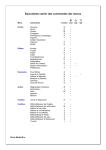
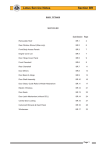
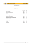
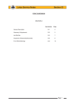
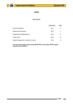
SECTION FJ
Sub-Section
Page
Introduction
FJ.1
2
Gearchange Mechanism
FJ.2
3
Lubrication
FJ.3
7
Driveshafts
FJ.4
8
Transmission Replacement
FJ.5
11
Transmission Overhaul & Special Tools
FJ.6
12
See also Toyota transmission repair manual D120T0327J
Page 1
sn_fj_cyclone.indd 1
01/04/2005 10:24:54
Lotus Service Notes
Section FJ
FJ.1 - INTRODUCTION
The transmission assembly is an 'end on' type, mounted on the left hand end of the engine unit, and
comprises of the clutch housing, six speed gearbox, final drive gears, and differential. The unit is supplied by
Toyota, and is designated 'C64', (C = series; 6 = no. of gears; 4 = ratio set) with Toyota publication RM930E
covering the description and overhaul of this transmission. Two control cables are used to transmit the movement of the gearchange lever to the transmission selector housing, running along the centre of the cabin and
beneath the power unit.
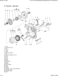
The two shaft six speed transmission is housed within a three part casing comprising clutch housing, main
case and end cover. The input shaft is supported by one roller bearing and two separate ball bearings, and
carries the clutch driven plate, the 3rd/4th synchroniser and the 5th/6th synchroniser, with the latter housed in
the end cover. The output shaft is similarly supported by one roller bearing and two ball bearings, and carries
the 1st/2nd synchroniser and the integral final drive pinion. All forward gears are constant mesh with inertia
lock type synchromesh, with reverse gear attained by sliding a spur idler pinion into engagement with a gear
on the periphery of the 1st/2nd synchroniser and a drive gear integral with the input shaft. All gears, with the
exception of reverse, use a helical tooth form for quiet running.
6th gear
5th gear
4th gear
3rd gear
2nd gear
1st gear
Reverse
Input shaft
f130
Ouput shaft
Double cone 2nd
gear synchromesh
Final drive gear
Sychromesh: For each gear ratio, one of the shafts has a fixed gear, and meshes with a freely revolving gear
on the other shaft. To engage a particular gear, the freely revolving gear must be connected to its shaft via
the sychro hub. As an example, third gear operates as follows: Under normal road driving, when the clutch
is depressed as a precurser to a gear change, the input shaft with the third gear synchroniser are de-coupled
from the engine but will be turning under inertia, clutch windage and oil drag. The freely revolving third gear is
driven by the fixed gear on the output shaft, which itself is driven by the roadwheels. Before the outer sleeve
of the synchroniser may be slid on its axial splines to engage with the spline ring integral with third speed input
shaft gear, the speeds of the two parts must be commonised. To aid this process, a sychroniser/baulk ring is
fitted between the two parts, being rotationally driven by the synchroniser, and equipped with a conical surface to
mate with a similar cone integral with the gear. Teeth on the outside of the synchro ring, over which the synchro
sleeve must slide before engaging the third gear splines, perform a baulking function described below:
Page 2
sn_fj_cyclone.indd 2
01/04/2005 10:24:55
Lotus Service Notes
Section FJ
When the gear lever is operated, the outer sleeve of the synchroniser is pushed towards third gear, and
pushes three spring detent plates which press the synchro ring onto the gear cone. As the input shaft train
is turning faster than third gear, the synchro ring is dragged to one end of its rotational constraint slots in the
synchroniser, in which position the internal spline teeth of the synchroniser sleeve are mis-aligned with the teeth
on the outside of the synchro ring. When further pressure is applied via the gearlever, the detent plates are
overidden, and the synchroniser sleeve splines are pressed against the ends of the sychro ring teeth, increasing the pressure on the conical surfaces. The bevelled ends of the sleeve splines and synchro ring teeth tend
to turn the ring into alignment, but whilst a speed differential between the ring and the gear remains, the cone
drag force is dominant and maintains spline mis-alignment. This is the 'baulk' function.
When the speed of the input train is synchronised to that of third gear, there ceases to be a force dragging
the synchro ring to the end of its slots, such that the bevelled ends of the splines allow the ring to move back
in its slot and for the synchroniser sleeve to be slid over the ring teeth towards the spline teeth on third gear..
These teeth, whose position in relation to those on the synchro ring was entirely at random when speed synchronisation occurred, are now freed to turn under the action of the spline end bevels, since there is no longer
any pressure applied to the cones. The sleeve completes engagement by sliding over the gear spline teeth to
connect the synchroniser to the gear.
In order to cater for the heavy demands made on the second gear synchroniser, and provide high durability,
this gear is fitted with a double cone mechanism to increase the conical surface area within a small space.
The selector mechanism cross shaft uses Teflon bushes to minimise friction, and a mass damper to improve gearchange feel. A slotted interlock cage allows the selector finger to operate only one selector shaft at
a time. In order to inhibit the unintended selection of reverse gear, a spring detent mechanism is arranged to
act on the cross-shaft, in conjunction with a lift collar at the gearchange lever.
A conventional 'open' bevel gear differential is contained in a housing bolted to the final drive output gear,
and supported in two taper roller bearings. An output extension shaft supported in a ball bearing mounted on
the cylinder block, is used on the right hand side to allow equal length drive shafts to be used. The driveshafts
use Rzeppa type joints on their outboard ends and plunging joints at the inboard ends to accommodate the
driveshaft length variation concomitant with suspension travel.
FJ.2 - GEARCHANGE MECHANISM
The gear lever is spring biased towards
the 3rd/4th gear plane, and must be moved
against light spring pressure to the left before
selecting first or second gear, or against similar
LIFT
pressure to the right before selecting 5th or
COLLAR
6th speed.
Engaging Reverse Gear:
With the vehicle at a complete standstill, pause for a moment with the clutch pedal
fully depressed before moving the lever to the
left, raising the lift collar beneath the knob, and
GEAR CHANGE PATTERN
then further to the left over a spring detent
before finally pushing forwards to engage the
gear.
A two cable mechanism is used to connect the gearchange lever with the transmission, one cable ('shift')
to transmit the fore/aft movement of the lever, and a second ('crossgate') cable for the sideways movement.
The gearchange lever is pivotted at its base and operates the shift cable directly via a ball joint half way up the
lever. The base of the lever has an extended ball pin on the right hand side which engages with a crossgate
bellcrank lever, the other leg of which operates the crossgate cable. An inhibit mechanism prevents the gear
lever being moved into the reverse gear plane unless a collar beneath the gear knob is lifted. The collar is
connected by control cable to a pivotted stop arm sprung to an 'up' position. In this position, a stop pin on the
crossgate bellcrank lever abuts against the end of the stop arm and prevents gearlever movement into the
reverse gear plane. When the collar is lifted, the stop arm is pulled down against its spring, to clear the stop
pin and allow reverse gate selection.
ohs15a
Page 3
sn_fj_cyclone.indd 3
01/04/2005 10:24:55
Lotus Service Notes
Section FJ
Gearchange Cable Schematic
Crossgate
Shift
Reverse gate lift collar
Reverse
gate
release
cable
Gear lever
ball pivot
Crossgate
bellcrank lever
Reverse gate
top arm
Crossgate cable
Shift cable
Abutment
block
f133
Transmission External Levers
'R' clip
'C' clip
Shift bellcrank lever
Inertia
weight
Transmission
cross-shaft
housing
Crossgate
lever
Crossgate cable
Shift cable
f132
Page 4
sn_fj_cyclone.indd 4
01/04/2005 10:24:55
Lotus Service Notes
Section FJ
The front end of both inner cables are equipped with socket joints which may be clipped on and off the ball
pins provided on the gearchange mechanism. The outer cables are retained by a forked plastic block bolted
into the gearlever/handbrake mounting frame.
The gear cables are routed along the centre of the cabin floor, beneath the fuel tank bay, and loop under
the engine to an abutment bracket on the top of the transmission housing. Both cables are retained in the
abutment bracket by spring 'C' clips. The shift cable is fitted on the left, and uses a bellcrank lever and ball
jointed link to connect with the transmission cross-shaft lever, in order to rotate the shaft. The cross-shaft lever
incorporates an inertia weight to smooth the gearchange action and improve feel. The crossgate cable is fitted
on the right and uses a centre pivotted lever arm to impart an axial motion to the transmission cross-shaft. The
ends of both inner cables threaded into alloy eyes which are retained on the lever pins by 'R' clips.
Gearchange Cable Adjustment
Under normal circumstances, no adjustment to the gear cables should be required. If a cable is replaced
in service, it may be necessary to make minor adjustments via the threaded ball joint at the front of the cable
in order to accommodate lever movement within the shroud aperture.
Gearchange Cable Replacement
For access to the gear cables, the gear lever shroud and parking brake lever trim must be removed: Unscrew the gear lever knob, remove the single screw each side of the shroud, and withdraw the shroud over the
gear and parking brake levers. Remove the engine bay undertray.
At the front end of the cables, unclip the inner cable ball joint sockets from the ball pins on the mechanism
levers. Release the outer cable plastic abutment block from the mounting frame. At the rear end of the cables,
remove the 'R' clips retaining the inner cable eyes to the levers, and the 'C' clips securing the outer cables to
the abutment bracket. Release the 'P' clips and cable ties as necessary to allow the cables to be withdrawn
from the car, noting the routing of the cables past the parking brake lever and wiring harness.
Refit in reverse order to removal, paying particular attention to the routing through or alongside the parking brake lever mounting frame.
Gearlever Mounting Frame
The gear lever/parking brake lever mounting frame is secured to thread inserts in the seat mounting crossmembers by two screws at the front, and a single screw at the rear. The whole assembly is offset towards the
passenger side of the car, with alternative fixing holes provided in the crossmembers.
Gearlever Replacement
The gear lever alone may be replaced if necessary using the following procedure. Note that fabrication
of the gear lever was changed in February 2005 from using a hexagonal section bar to a thicker round section
bar, the better to resist operator abuse. Only the later type will be supplied in service, which if being used to
replace the hexagonal type will require fitment of the following parts as a set:
Parts Required
Gear Lever - RHD
Gear Lever - LHD
Lift Tube, reverse select
Lift Tube Adaptor
Spring Clip, lift tube to adaptor
Knob, gear lever, M10
Tool, gear lever bush guide
Part Number
A120F0008S
A120F0009S
B120U0017F
A120F6259S
B120W6770F
C120U0012F
A120U0054S
Qty
1
1
1
1
1
1
1
Procedure
1. Release the grub screw (if applicable) in the front face of the gear lever knob, and unscrew the knob. For
knobs without grub screws, gentle heat may help to soften the thread adhesive. Prise off the spring clip
from the top of the lift tube adaptor.
2.
Release the two grub screws in the underside of the parking brake lever sleeve and withdraw the
sleeve.
3.
Remove the two screws securing the front of the gear lever shroud and carefully withdraw the gear/park
Page 5
sn_fj_cyclone.indd 5
01/04/2005 10:24:56
Lotus Service Notes
Section FJ
brake shroud, disconnecting the window switch and hazard lamps switch (if applicable). Take care to
prevent scratching the shroud on seat belt fixings or seat runners.
4.
Release the reverse selector cable from the gear lever and unhook from the lift tube adaptor. Discard the
adaptor.
5.
Prise off the gear selector cable socket from the gear lever (use a 10mm spanner).
6.
From the LH side of the unit, remove the screw securing the gear lever pivot to the mounting frame. Push
the top of the gear lever to the right to help disengage the crossgate selector ball at the bottom of the lever
from the bellcrank lever socket. Take care not to damage the socket plastic bush which should remain in
the bellcrank lever. Discard the gear lever.
7.
To allow fitment of the bush guide tool, unhook the main harness from the 'P' clip at the front of the frame,
temporarily hook over the outside of the shroud fixing leg and rotate the 'P' clip 90°. Locate the guide tool
in the hole at the RH side of the mounting frame and secure in position using a 'G' clamp as shown, but
do not crush or distort the frame.
Bellcrank lever plastic socket
'G' clamp
Use suitable bolt to
push back socket
(Some components omitted for clarity)
Special tool
A120U0054S
f135
8.
Push the plastic socket in the bellcrank lever fully into the guide tool to facilitate installation of the gear
lever. Apply a dab of mineral oil based lithium grease (e.g. Molykote Longterm W2) to the socket.
9.
Fit the gear lever, feeding the crossgate ball into the bellcrank lever and position the lever upright. Using
a suitable screwdriver or pry bar, push the base of the lever over to the right to engage the crossgate ball
into the plastic socket (should click home).
Page 6
sn_fj_cyclone.indd 6
01/04/2005 10:24:56
Lotus Service Notes
Section FJ
10. Remove the 'G' clamp and guide tool, and push the crossgate socket to the left to engage the 'D' feature
on the gearlever pivot ball with the matching hole in the LH side of the frame. Apply Permabond A130
(A912E6033V) to the fixing screw and torque tighten to 10 Nm. Restore harness position.
'D' spigot on lever
pivot ball
'D' hole in mounting frame
f136
11. Fit the new lift tube adaptor onto the gear lever and ensure it is free to slide up and down. Hook in the
reverse selector cable and secure to the gear lever abutment. Temporarily fit the new lift tube onto the
adaptor and screw on the new gear knob. Adjust the cable to allow correct reverse gear selection and
tighten adjuster nuts. Remove gear knob and lift tube. Clip the selector cable onto the gear lever ball.
12. Cut the tie strap securing the old lift tube in the gear lever gaiter and fit the new lift tube using a suitable tie
strap. Fit the shroud over the parking brake and gear lever, taking care not to scratch the surface finish,
and aligning the flats on the lift tube with those on the lift tube adaptor. Connect the electrical switches as
necessary, and retain the shroud with the two screws.
13. Use the new spring clip to secure the lift tube to the adaptor, and fit the new gear knob, tightening the grub
screw to orientate the graphic correctly. Fit and secure the parking brake lever sleeve.
14. Check gear selection and reverse inhibit function. Ensure the lift tube returns freely under spring action.
FJ.3 - LUBRICATION
The transmission should be checked for oil leaks, for the correct oil level, and the oil renewed, at intervals
specified in the Maintenance Schedule.
Transmission oil viscosity; SAE 75W/90
Transmission
Specification;
API GL-4 or GL-5
filler/level
Quantity;
2.3 litres
plug
To check the oil level:
Remove the engine bay undertray.
Wipe clean the area around the socket
headed level plug on the front face of the
transmission main casing.
Remove the plug, and check that the oil
Drain
is level with the bottom of the hole. Note
plug
that the release of oil trapped by the plug,
should not be confused with an indication
of correct oil level.
If necessary, add only the specified lubricant (see above) via the level plug hole until the oil level stabilises
at the bottom of the plug hole.
Alternatively, oil may be added into the top of the transmission via a mechanical speedo drive (not used
in this application) cover at the right hand top of the transmission, after removing the single screw.
f131
Page 7
sn_fj_cyclone.indd 7
01/04/2005 10:24:56
Lotus Service Notes
-
Section FJ
Refit the level plug with a new sealing washer, and tighten securely.
To renew transmission oil:
The hexagon headed drain plug located at the bottom of the final drive casing, should be removed immediately after a run when the oil is warm, taking suitable precautions against scalding.
Clean the plug, fit a new sealing washer and refit securely.
Refill to the level plug hole as detailed above.
FJ.4 - DRIVE SHAFTS
Each of the two driveshaft assemblies comprises a steel shaft with a constant velocity joint at each end,
and is used to transmit the drive from each differential output gear to the rear wheel hub. The two driveshaft
assemblies are similar, but the inboard joint of the right hand shaft is supported in an outrigger bearing bolted
to the right hand side of the cylinder block, and uses an integral extended shaft to reach into the transmission
housing. The inboard joints are of a plunging 6-ball double offset design to accommodate driveshaft length
variation with suspension travel, whereas the outboard joints are high efficiency 8-ball fixed type.
Replacement outboard joints include the main driveshaft (longer on the RH side), outboard C.V. joint and
gaiter. Replacement inboard joints include the inner C.V. joint and gaiter kit, with the extended stub shaft of
the RH joint also including the support bearing and mounting bracket.
The joints themselves are packed with grease on initial assembly, and are maintenance free. It is however
vitally important that the protective gaiters are carefully inspected at service intervals, to check for splits, tears
or punctures, since the joint will deteriorate very quickly once contaminated with dirt or water. Damaged gaiters
should be renewed immediately, once the servicibility of the joint has been established.
CAUTION: The outboard C.V. joint gaiter can suffer 'pinch' damage if the joint is subjected to extreme articulation off the car, or during driveshaft removal/refitment.
RH Driveshaft Assembly
f128
Outboard joint
Main shaft
Inboard joint
Extension shaft
Support bearing
LH Driveshaft Assembly
f129
Outboard joint
Main shaft
Inboard joint
Circlip
Page 8
sn_fj_cyclone.indd 8
01/04/2005 10:24:57
Lotus Service Notes
Section FJ
Clicking noises, torque reversal 'clonks', or shudder and vibration when accelerating are all possible symptoms of worn C.V. joints. It should not be possible to discern any free play in a joint, but care must be taken not
to confuse this with transmission backlash, which may be considerable. Any symptoms that could be due to
worn driveshaft joint assemblies, should be investigated and rectified without delay, since safety considerations
are always of paramount importance.
The inboard C.V. joint is equipped with a male splined spigot shaft which engages with the female splines
of the differential output sun gear, with the LH shaft retained by a round section spring circlip on its end, and
the RH shaft retained by the extension shaft support bearing. Each of the two transmission output oil seals
runs on a stepped shoulder on the C.V. joint spigot shaft. The stub shaft of each outboard joint is splined into
the wheel hub, and retained by a nut on the threaded end of the shaft.
Driveshaft Assembly Replacement
Removing a driveshaft assembly from the transmission will result in some loss of transmission lubricant.
It may be preferred to drain off some oil via the transmission drain plug beforehand.
1. Remove the transmission drain plug and drain off approximately 1 litre of oil into a clean container for reuse.
2.
Remove the rear road wheel.
3.
Remove the split pin from the hub nut and remove the nut and washer (right hand thread on both sides).
Before the shaft can be withdrawn from the hub, the top ball joint plinth must be released from the hub
carrier (note camber shims fitted), and the toe-link ball joint separated from the carrier. This will allow the
hub carrier to be pulled away sufficiently for the driveshaft to be withdrawn, but take care not to strain the
brake hose or wheel speed sensor harness.
4.
LH Driveshaft: The left hand driveshaft inboard joint is retained in the transmission by a round section
circlip. The joint may be removed by applying a shock pull to the C.V. joint body using a slide hammer
with a forked end.
CAUTION: Do NOT attempt to remove the inboard C.V. joint from the transmission by pulling on the
driveshaft. The balls of the inboard joint are restrained for transit purposes only, by a circlip at the end of
the ball tracks. Applying an extension force to the joint will damage the balls and require joint replacement.
Apply pressure only to the outer body of the joint.
RH Driveshaft: The right hand driveshaft incorporates a bearing for the extension shaft and it is this which
retains the shaft in the transmission. Remove the two bolts securing the bearing bracket, and withdraw
the complete shaft assembly.
When withdrawing either splined shaft from the transmission, take great care not to damage the ouput oil
seal.
6.
Before re-fitting a driveshaft, first renew the round section circlip on the end of the left hand inboard joint
spigot shaft, and lubricate the circlip with grease. Also, check the condition of the transmission output seal,
and renew if necessary. Lubricate the lip of the seal with transmission oil, and grease the corresponding
shoulder on the driveshaft (C.V. joint) spigot, to reduce the danger of damaging the seal on assembly.
7.
Carefully insert the driveshaft into the transmission, with, on the left hand shaft, the two ends of the circlip
positioned lowermost, and rotate the shaft if necessary to engage the splines. Press the inboard joint outer
until a click indicates the engagement of the retaining circlip, if necessary using a brass drift and hammer.
Pull on the body to ensure its security. On the right hand shaft, fit the bolts securing the extension shaft
bearing to the engine mounted bracket, and torque to 64 Nm.
8.
Fit the outer end of the shaft into the hub, and refit the top ball joint plinth to the hub carrier with the camber adjustment shim pack in position. Apply Permabond A130 (A912E7033V) to the threads of the two
socket head bolts and torque to 45 Nm.
9.
Refit the toe-link into the hub carrier and torque the retaining nut to 55 Nm.
10. Fit the washer and castellated nut to the driveshaft, apply the parking brake and tighten the nut to 220
Nm. Fit a new split pin to lock the nut.
Page 9
sn_fj_cyclone.indd 9
01/04/2005 10:24:57
Lotus Service Notes
Section FJ
11. With the car on a level surface, top up the transmission oil to the filler/level plug hole.
Driveshaft C.V. Joint and/or Gaiter Replacement
The outboard C.V. joint is supplied complete with main driveshaft to which it is fixed by a spline with a small
helix angle to eliminate any potential backlash. Separation of the shaft from the joint should not be attempted.
Note that the RH main shaft is 22mm longer than the LH shaft. Replacement of the outboard joint gaiter entails
removal of the complete driveshaft assembly from the car, and removal of the inboard joint from the shaft.
1. Remove the driveshaft assembly from the car (see above).
2.
Remove the clips securing the inboard joint gaiter without damaging the gaiter if it is to be re-used. Pull
the gaiter off the joint outer body, remove the circlip in the end of the joint outer body and match mark the
body to the joint inner race before sliding the body off the shaft assembly.
3.
Remove the circlip from the end of the shaft and match mark the inboard joint inner race to the shaft before
pulling or pressing the race from the shaft. Slide the inboard gaiter off the shaft.
4.
Remove the clips securing the outboard gaiter, and slide the gaiter off the shaft.
5.
Inspection & Cleaning: Complete disassembly of either joint is NOT recommended. The separate components are a precision fit and develop their own individual wear patterns, such that any interchanging or
re-orientation of parts is likely to result in premature failure.
If the grease in the joint is contaminated with dirt or water, it is likely that the joint is damaged, and should
be replaced. If the grease is not contaminated, the joint should be degreased by soaking in a suitable
solvent (NOT petrol), and then carefully inspected. Tilt the inner race to one side to expose each ball.
Severe pitting, galling, play between ball and its cage window, any cracking or damage to the cage, or
pitting, galling or chips in raceways, call for joint replacement.
If the joint is found to be serviceable, it must be repacked with the special grease provided. Pack the
grease into the joint itself and also into the inside of the new gaiter.
NOTE: The grease provided in the kits is specially formulated for wear resistance and durability. DO NOT
use substitutes or mix with other lubricants. The grease specification and quantity also differs for inboard
and outboard joints, so care must be taken to apply correctly.
6.
Slide the new outboard gaiter and smaller retaining clip onto the shaft. Fit the gaiter into the grooves on
the outboard joint body and the driveshaft, and secure with the clips provided.
8.
Slide the new outboard gaiter and retaining clip onto the driveshaft and press the joint inner race onto the
driveshaft splines with the match marks aligned (if re-using joint). Retain with a new circlip.
9.
Fit the inboard joint body to the shaft assembly with the match marks aligned (if re-using joint), and fit a
new circlip into the end of the housing to retain the joint.
10. Fit the gaiter into the grooves on the joint outer body and driveshaft and secure with the new gaiter
clips.
11. Refit the driveshaft to the car (see above).
Extension Shaft Support Bearing
The ball bearing supporting the RH driveshaft extension shaft to the engine block is mounted in a housing
which is bolted to a bracket on the engine block. The bearing is sealed and maintenance free, and is included
as part of the inboard C.V. joint assembly, but may if necessary be renewed by the following procedure:
1.
Remove the RH driveshaft assembly (see above).
2.
Using a press, remove the dust shield from the inboard end of the shaft.
3.
Remove the circlip from the outboard face of the bearing housing, and press or pull the housing from the
bearing.
Page 10
sn_fj_cyclone.indd 10
01/04/2005 10:24:57
Lotus Service Notes
Section FJ
4.
Prise or pull the bearing dust shield off the shaft.
5.
Remove the circlip retaining the bearing and press or pull the bearing from the shaft.
6.
Press a new bearing into the housing,
and retain with a new circlip. Then use
special press tool T000T1438F to press
the inner race of the bearing up to the
shoulder on the shaft, and retain with a
new circlip.
f125
7.
Use special press tool T000T1439F to
press the bearing dust shield onto the
shaft and position as shown in the illustration.
f126
8.
Press the inboard dust shield onto the
end of the shaft to the dimension shown
in the illustration.
9.
Refit the driveshaft to the car (see
above).
86.5 ± 0.5mm
f127
FJ.5 - TRANSMISSION REPLACEMENT
The transmission may be removed from below after removing the left hand rear suspension assembly,
both driveshaft assemblies and the exhaust system. Release the clutch release fork, gearchange cables, earth
braid and reverse light switch.
The engine must be supported to allow the engine and transmission mountings to be disconnected and
the power unit tilted as necessary to allow the transmission to be withdrawn. The clutch bell housing is secured
to the engine by 8 bolts as shown overleaf.
Page 11
sn_fj_cyclone.indd 11
01/04/2005 10:24:57
Lotus Service Notes
Section FJ
Clutch housing to engine fixings - viewed from gearbox side
M12x55 flange head bolts to block; 64 Nm
M10x65 bolts also secure
starter motor; 37 Nm
M10x55 bolts to
block; 37 Nm
f134
M10x30 bolts to sump; 23 Nm
FJ.6 - TRANSMISSION OVERHAUL
The overhauling of the Toyota supplied type C64 transmission, is detailed in separate publication
D120T0327J. Special tools are available through Lotus under the following part numbers:
Transmission Special Tools
Description
Press Dolly, driveshaft bearing
Press Dolly, driveshaft bearing shield
Oil Seal Puller
Differential Preload Adaptor
5th/6th Gear Puller Kit
comprises:
Upper Plate
Centre Bolt
Arm (x3)
Adaptor
5th/6th Synchro Hub Puller Kit
comprises
Hanger
Slide Arm (x2)
Centre Bolt
Claw no.2 (x2)
Holder
Output Shaft Seal Replacer Dolly, LH
Output Shaft Seal Replacer Dolly, RH
Output Shaft Seal Replacer Handle
Lotus Part No.
T000T11438F
T000T1439F
T000T1445S
T000T1446S
T000T1447
T000T1447/1
T000T1447/2
T000T1447/3
T000T1447/4
T000T1448
T000T1448/1
T000T1448/2
T000T1448/3
T000T1448/4
T000T1448/5
T000T1459F
T000T
T000T1460F
Page 12
sn_fj_cyclone.indd 12
01/04/2005 10:24:58
Lotus Service Notes
Section FJ
Transmission Overhaul Notes
1. Removing and installing 5th and 6th driven gears from the end of the ouput shaft requires considerable
force. The specified puller tools should be used, but when pulling 5th speed driven gear, the claws of the
tool may require some grinding to allow complete and proper fitment, and an anti-spreading device is recommended to be fitted around the three claws. Striking the puller bolt with a hammer in between tightening
steps will help shock the gear from its interference fit, and engaging two gears to lock the transmission
will also aid the process.
2.
The preload on the differential carrier taper roller bearings is controlled by shims between the bearing
outer race and the clutch housing, and is determined by installing the final drive assembly in an otherwise
empty casing, and measuring the steady rotation torque.
3.
If the input shaft oil seal is to be replaced, the bearing should also be renewed since this is likely to be
damaged during oil seal removal.
4.
The reverse select compression spring shown in the Toyota Repair Manual is not fitted in the Lotus application.
Page 13
sn_fj_cyclone.indd 13
01/04/2005 10:24:58
Lotus Service Notes
Section FJ
Page 14
sn_fj_cyclone.indd 14
01/04/2005 10:24:58