1
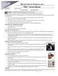
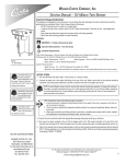
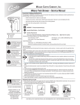
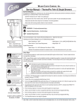
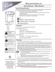
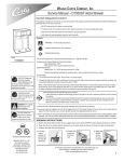
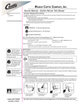
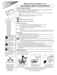
Wilbur Curtis Company, Inc.
Service Manual – ThermoPro Server
Models Included:
TLXG1
TLXG15
TLXG2
WARNING – THERMOPRO SERVERS MAY BE HEAVY WHEN FILLED.
CARE MUST BE TAKEN WHEN TRANSPORTING TO AVOID DROPPING OR SPILLING.
Use only coffee or water in the insulated dispenser. Do not use the thermoserver to dispense any other beverage. Preheating is
recommended.
1. Place a clean and empty server centered under one of the brewcones of the ThermoPro brewer.
2. Make sure the screen reads READY TO BREW.
3. Fill brewcone with the correct measure of ground coffee for the volume of coffee you wish to brew.
4. Press the desired brew button on the side of the brewer with server you wish to brew into.
5. Allow coffee in the brewcone to drip completely before removing the insulated server.
SERVICING THE THERMOPRO SERVER
1. Completely drain the unit of any coffee.
2. Allow server to cool.
3. Unscrew and remove the lid and tube assembly.
REPLACING THE GAUGE GLASS
The gauge glass can be removed for maintenance and cleaning. Refer to the illustration on page three [3] for assembly sequence.
1. Unscrew the vented cap plug from the top of the gauge glass shield.
2. Carefully lift out the gauge glass tube from the shield and scrub inside the glass with a tube cleaning brush and mild detergent solution. Inspect the glass tube for cracks or chips. If broken, carefully remove all traces of glass and then insert a new gauge glass tube.
3. Check the top and bottom washers that make the tube water tight. Clean the washers. Make sure they are not leaking. Replace if necessary.
4. With the sight glass seated in the gauge glass shield, thread the cap plug onto the top of the shield. Do not overtighten.
REMOVING THE BASE & BOTTOM COVER
To replace the silicone elbow fitting for repair or cleaning:
1. Remove the base assembly, taking out four screws.
2. Remove the base adapter, taking out three screws.
3. Take off the white plastic bottom cover to reveal the silicone elbow fitting.
4. Squeeze the wire hose clamp and pull elbow from the liner drain pipe. Loosen the hose clamp holding the elbow to the faucet shank and remove elbow.
5. Check for leaks and replace with new part if necessary.
6. Reverse these steps to assemble.
REMOVING THE FAUCET
The faucet will require periodic cleaning and maintenance.
1. Remove the faucet from the body of the server.
Unscrew the wing nut from the faucet and the faucet will come off.
2. Disassemble the faucet. Unscrew the bonnet from the body of the faucet.
3. Remove the faucet handle by pressing inward on the seat cup (fig. 1.) then unhooking the handle from the center shaft.
4. The seat cup, center shaft and spring will now separate from the bonnet.
5. You may now clean the parts of the faucet (fig. 2). Check the seat cup for tearing of splitting. Make sure that the faucet spring is free of corrosion. Replace these items if necessary (item 13, page 3).
ASSEMBLY
Assemble the unit by reversing the steps for disassembly. Finger tighten only wing nut for faucet. Make sure
clamps are on properly and all silicone fittings are in good condition. Once assembled, check for leaks around
fittings or faucet.
1
Cleaning and Sanitizing Instructions
CAUTION
Do not immerse in water.
Do not place in dishwasher.
Do not use harsh powders or cleansers containing chlorine.
Do not use a wire brush or pot scourer to clean inside liner.
These cleaning and sanitizing instructions are only a guide line to be used for the cleaning and sanitizing of the TLXG15. Your current in-house cleaning and sanitizing methods may be just as effective.
For cleaning and sanitizing of the TLXG15, the three sink method is recommended. This method consists of a sink of water filled
with a detergent and water solution, a fresh water rinse, and a sink filled with an aqueous sanitizing solution. Immerse in commercial
BarTabs/Sani-Tabs sanitizing solution. The solution must be warm (75°F.) Let the parts soak at least one minute.
1. Daily, Rinse the unit after use.
a. Rinse unit with hot water and empty completely.
b. Fill unit with hot water.
c. Open unit and empty contents completely.
2. Clean and sanitize the lid assembly.
a. Remove lid from unit and submerse it in cleaning solution, cleaning thoroughly.
b. Using the supplied brush, clean inside the filling tube.
c. Rinse with clean water.
d. Submerse in sanitizing solution for 5 minutes then air dry completely.
3. Cleaning and sanitizing body assembly.
a. Completely fill the unit with cleaning solution. With a sponge brush, thoroughly clean inside liner.
b. Rinse the unit using a fresh water rinse.
c. Fully fill unit with sanitizing solution. Allow to sit for 5 minutes then drain through the faucet.
d. Remove faucet and gauge glass from unit and brush out with cleaning solution.
e. With the faucet removed, clean the silicone elbow fitting (Tank to Faucet Tube). Use the tube brush soaked in cleaning solution, inserted through the faucet shank. Rinse by pouring water from inside the unit, allowing rinse water to flow into a sink until water runs clear.
f. Wipe outside of unit with clean cloth moistened with cleaning solution.
g. Place body assembly upside down on rack to thoroughly air dry.
4. Cleaning the faucet parts.
a. Unscrew the bonnet/handle assembly from the faucet and disassembly removing spring, seat cup and shaft.
b. Clean and rinse parts. Place in sanitizing solution for 5 minutes, remove and air dry,
5. When all pieces are completely dry reassemble for use.
Rough-In Drawing
TLXG1
21.13”
(53.7 cm)
TLXG15
23.13"
9.25"
13.50" (23.5 cm)
(58.8 cm)
TLXG2
23.25”
(59.1 cm)
(34.3 cm)
9.00"
3.25"
(22.9 cm)
(8.3 cm)
9.00"
(22.9 cm)
2
12.50"
(31.8 cm)
Illustrated Parts
ThermoPro Gravity Pot
5
6
7
8
9
10
11
12
13
14
15
16
17
19
18
20
21
Illustrated Parts List
All parts are common amoung 1, 1½ and 2 gallon servers, except where noted.
Index
Nº
1
1A
2
3
4
5
5A
5B
6
6A
6B
7
8
Part
Nº
WC-56008
WC-56019
WC-2003
WC-2002
WC-2005
WC-2027
WC-2025
WC-2030
WC-2012
WC-2010C-101
WC-2017
WC-1939
WC-1938
Description
Index
Nº
LID ASSY, TLXG15 Z-TYPE
LID ASSY, TLXG1 Z-TYPE
CAP PLUG, VENTED 44
CAP SHIELD W/CLEANOUT
WASHER, SHIELD CAP 1/8”
GLASS, GAUGE 10” TLXG15
GLASS, GAUGE 8” TLXG1
GLASS, GAUGE 13” TLXG2
SHIELD, GAUGE GLASS 10” TLXG15
SHIELD, GAUGE GLASS 8” TLXG1
SHIELD, GAUGE GLASS 13” TLXG2
NUT, FLANGED TLS-2
SHANK, PLASTIC CAP-T2
9
10
11
12
13
14
15
16
17
18
19
20
21
Part
Nº
WC-2006-101
WC-2004
WC-1905
WC-1906
WC-3705
WC-1841
WC-64067
WC-3699
WC-2426
WC-56013
WC-36076
WC-38281
WC-5680
Description
WASHER, .188 x .188
SHIELD BASE
NUT, WING PLASTIC
C’ RING .917 x .760 x .090
KIT, FAUCET REPAIR
FAUCET, ESP BLACK
GUARD, FAUCET TLXG15 Z-TYPE
INSULATION, TUBE SLIT 3/8” THK
ELBOW, SILICONE TLXG15 Z-TYPE
BASE ASSY, SERVER
BRUSH, GAUGE GLASS
LABEL, DECAF
DRIP TRAY, THERMOSERVER
3
Product Warranty Information
The Wilbur Curtis Company certifies that its products are free from defects in material and workmanship under normal
use. The following limited warranties and conditions apply:
3 Years, Parts and Labor, from Original Date of Purchase on digital control boards.
2 Years, Parts, from Original Date of Purchase on all other electrical components, fittings and tubing.
1 Year, Labor, from Original Date of Purchase on all electrical components, fittings and tubing.
Additionally, the Wilbur Curtis Company warrants its Grinding Burrs for Forty (40) months from date of purchase or 40,000 pounds
of coffee, whichever comes first. Stainless Steel components are warranted for two (2) years from date of purchase against leaking
or pitting and replacement parts are warranted for ninety (90) days from date of purchase or for the remainder of the limited warranty
period of the equipment in which the component is installed.
All in-warranty service calls must have prior authorization. For Authorization, call the Technical Support Department at 1-800-9950417. Effective date of this policy is April 1, 2003.
Additional conditions may apply. Go to www.wilburcurtis.com to view the full product warranty information.
CONDITIONS & EXCEPTIONS
The warranty covers original equipment at time of purchase only. The Wilbur Curtis Company, Inc., assumes no responsibility for
substitute replacement parts installed on Curtis equipment that have not been purchased from the
Wilbur Curtis Company, Inc. The Wilbur Curtis Company will not accept any responsibility if the following conditions are not met. The
warranty does not cover and is void under the following circumstances:
1)
2)
3)
4)
5)
6)
7)
8)
9)
Improper operation of equipment: The equipment must be used for its designed and intended purpose and function.
Improper installation of equipment: This equipment must be installed by a professional technician and must comply with all local electrical, mechanical and plumbing codes.
Improper voltage: Equipment must be installed at the voltage stated on the serial plate supplied with this equipment.
Improper water supply: This includes, but is not limited to, excessive or low water pressure, and inadequate or fluctuating water flow rate.
Adjustments and cleaning: The resetting of safety thermostats and circuit breakers, programming and temperature
adjustments are the responsibility of the equipment owner. The owner is responsible for proper cleaning and regular maintenance of this equipment.
Damaged in transit: Equipment damaged in transit is the responsibility of the freight company and a claim should be made with the carrier.
Abuse or neglect (including failure to periodically clean or remove lime accumulations): Manufacturer is not responsible for variation in equipment operation due to excessive lime or local water conditions. The equipment must be maintained according to the manufacturer’s recommendations.
Replacement of items subject to normal use and wear: This shall include, but is not limited to, light bulbs, shear disks, “0” rings, gaskets, silicone tube, canister assemblies, whipper chambers and plates, mixing bowls, agitation assemblies and whipper propellers.
Repairs and/or Replacements are subject to our decision that the workmanship or parts were faulty and the defects showed up under normal use. All labor shall be performed during regular working hours. Overtime charges are the responsibility of the owner. Charges incurred by delays, waiting time, or operating restrictions that hinder the service technician’s ability to perform service is the responsibility of the owner of the equipment. This includes institutional and correctional facilities.
The Wilbur Curtis Company will allow up to 100 miles, round trip, per in-warranty service call.
RETURN MERCHANDISE AUTHORIZATION: All claims under this warranty must be submitted to the Wilbur Curtis Company
Technical Support Department prior to performing any repair work or return of this equipment to the factory. All returned equipment must be repackaged properly in the original carton. No units will be accepted if they are damaged in transit due to improper
packaging. NO UNITS OR PARTS WILL BE ACCEPTED WITHOUT A RETURN MERCHANDISE AUTHORIZATION (RMA). RMA
NUMBER MUST BE MARKED ON THE CARTON OR SHIPPING LABEL. All in-warranty service calls must be performed by an
authorized service agent. Call the Wilbur Curtis Technical Support Department to find an agent near you.
WILBUR CURTIS CO., INC.
6913 Acco St., Montebello, CA 90640-5403 USA
Phone: 800/421-6150 Fax: 323-837-2410
Technical Support Phone: 800/995-0417 (M-F 5:30A - 4:00P PST)
Web Site: www.wilburcurtis.com
4
E-Mail: [email protected]
Printed in U.S.A.
ecn 10071 . 10/3/8 @ 13.7 . revE.
ECN 9369 . 11/9/7 @ 10.7 . rev D
ECN 8939 5/1/7 @ 10.3 . rev C
ECN 8723 1/12/7 @ 8.8
11/08
F-3402 Rev E