1
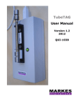
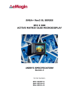
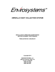
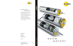
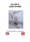
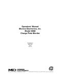
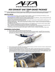
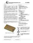
w w w. e n v i r o k l e a n . c o m
Enviro-Klean - 1980’s to Present
Enviro-Klean’s Roots
Back in the 1980’s, manufacturers of asphalt plants
began modifying their equipment to remediate
hydrocarbon contaminated soils. The process was
effective, however, fuel consumption and undesirable
air emissions presented significant challenges.
As a result, a group of engineers joined forces under
the name Enviro-Klean and began to explore alternate
soil heating methods. They created the unique EnviroKlean soil curtain design, which has been modified
and improved through 4 generations.
Each new enhancement has increased the throughput,
reduced energy consumption and improved air
emissions. Today’s model, the KM-4, is a testimony
to the company’s unceasing pursuit of perfection.
This second generation Klean Machine was designed and built in 1994
Material
Feed
Air Filter
Soil Processor
Certified Engineering and Manufacturing
Enviro-Klean equipment is engineered and manufactured in North America,
and meets UL, CSA and European CE standards.
All machine components are designed for years of productive service. (The KM-2
pictured above was built in 1994 and is still in operation.) The drives and gear boxes
used to power the screw conveyors and augers are top-of-the line Eurodrive and
Baldor. The electronics are Siemens. The fuel system is Eclipse. The heavy-duty
trailers feature air-ride suspensions.
Enviro-Klean is committed to providing competitive, state-of-the-art thermal
remediation equipment that meets or exceed the toughest environmental standards
world-wide.
For Additional Information on Thermal Desorption
The US Navy has commissioned hundreds of clean-ups, and has complied an intensive analysis
of this technology, titled “Application Guide for Thermal Desorption Systems.”
It includes the following topics:
1. When to Use Thermal Desorption
2. Design and Performance Characteristics
3. Cost Data and Project Estimating Methodology
4. Regulatory Compliance Issues
5. Case Studies
You can review a copy of this report on the Enviro-Klean website at:
www.enviroklean.com/USNavyReport
2
w w w. e n v i r o k l e a n . c o m
Oxidizer
How Does It Work?
The Enviro-Klean thermal
desorber is effective for removing
hydrocarbon contamination from
the soil.
Hydrocarbons volatilize when
heated to their boiling point and
subsequently convert to water vapor
and carbon dioxide in a thermal
oxidizer. The net result is reusable
clean soil.
What Can it Clean?
The Enviro-Klean thermal desorber
can clean gasolines, jet fuel,
kerosene, diesel, lube oil…virtually
any petroleum product.
In addition, with modifications,
these versatile machines can clean
soil containing pesticides,
chlorinated compounds, plus
recover entrained oil in drill
cuttings.
Patented Soil Processor Design
The Patented Enviro-Klean Processor
Thermal desorption machines share three common features:
1
♦ a processor for heating the soil to release the contaminants,
♦ a oxidizer or condenser for removing the organics,
♦ a baghouse for containing the particulate.
2
Most thermal machines use a double-shell rotary drum to heat
and volatilize the contaminants. The residence time for soil in
the drum averages 6 to 12 minutes—depending on soil type,
moisture, contaminant, etc.
3
Enviro-Klean has a patented soil-curtain processor with an
average residence time of about one minute. Contaminated soil
falls in thin layers between the processor chambers—which
allows for maximum heat transfer between the heated air
and the soil.
There are three primary savings with this system:
♦ less energy is required to heat the contaminants,
♦ soil moves through the processor faster which allows the
Enviro-Klean machine to do the same job as one twice its size,
♦ the airstream is considerably smaller making it easier to
control.
The net result is Enviro-Klean’s ability to put all three
of the necessary thermal desorption components on a
single highway-legal trailer—making the system smaller,
less expensive to operate and significantly reducing the capital
cost.
4
Back view of KM-3 design during construction
showing narrow, compact processor
(chambers are numbered 1 through 4).
1
2
3
Side view of a KM-3 design
during construction
showing three of the four
processor chambers.
Soil Curtain
Inside view of a processor chamber showing the screw, trough, and drop zone.
Soil cascades down through the processors, while heated air volatilizes the contaminants.
w w w. e n v i r o k l e a n . c o m
3
Enviro-Klean KM-4
The Standard for Fuel Efficiency
Patented Processor
Saves 50% on Fuel Costs
KM-4 DIMENSIONS*
Traditional rotary kiln thermal desorbers use twice as much fuel for
the same throughput as the KM-4.
Here is how the KM-4 design squeezes every drop of potential from
its burner fuel.
• The processor and thermal oxidizer walls are foam insulated,
which is up to 3 times more effective than hard refractory.
Radiation losses are minimal.
• The cascading soil design helps to volatilize the hydrocarbons at
30% lower airstream temperatures.
• And since the airstream is half the volume of a rotary kiln, less
energy is required to destroy the hydrocarbons in the thermal
oxidizer, and less energy is needed to cool the air prior to the
baghouse.
The result of these design enhancements provides today’s thermal
remediation market with the fastest throughput, the lowest operating
cost, and the most advanced options for remediating difficult
hydrocarbon contamination.
In-feed
Hopper
Thermal Oxidizer
Burner
Thermal
Oxidizer
Transport:
• Highway-legal on most
commercial transport roads
world-wide.
Trailer mounted:
• Includes material processor,
thermal oxidizer, heat exchanger
and baghouse
• 16 meters (53’)
• 4 meters (13’2”)
• 2.5 meters (8’2”)
• 33 tonnes (73,000 lbs)
Trailer Length:
Equipment Height:
Trailer Width:
Total Weight:
*Note: Due to on-going product upgrades, specifications
and designs are subject to change without notice.
Items shipped may differ from those described
in this catalog.
Multi
Clone
Heat
Exchanger
Baghouse
I.D. Fan
Burner Assembly
4
w w w. e n v i r o k l e a n . c o m
Enviro-Klean KM-4
Portable and Reliable
Compressor
Electrical
Panel
Processor
Assembly
The Ultimate, High-Capacity
Portable Thermal Desorber
The Enviro-Klean KM-4 is designed to minimize nonproductive time. For faster mob/demob, the width and
height dimensions are within North American and
European road regulations. The trailer connects to any
heavy-duty truck and is immediately ready for transport.
Set-up is straightforward. Unlike rotary kilns, there is no
cumbersome ductwork to connect, and no large cranes
needed to position the skids. Instead, the trailer is towed
by the truck to a suitable, reasonably-level site. Then a
few smaller components, notably the material feed and
discharge system, are set in place and the equipment is
ready for operation.
Cost-Effective for Smaller Projects
The KM-4 is especially effective for smaller remediation
projects and rapid turn around times because it can be set
up in less than a day. Competing equipment often requires
a week or more, which adds significantly to the project
cost and manpower requirements.
When small projects are time-consuming and costly, the
contaminated soil is frequently trucked to a central site
or a landfill—relocating the problem elsewhere and
necessitating new fill material. This option is
environmentally unfriendly and potentially dangerous.
Material
In-feed
Preheater
KM-4 SPECIFICATIONS*
Nominal Feed Rate: • 18-27 tonnes (20-30 tons) per hour
Contaminants:
• Hydrocarbons to 25,000 mg/kg
and to Carbon Chain 40 at
reduced throughput
Moisture:
• 20% maximum recommended
(<15% preferred)
Processor Temp:
• 315-930°C (600-1700°F)
Fuel:
• Propane, natural gas
or #2 fuel oil
• <100 ppm to non-detect
CO:
VOCs:
• Meets legal requirements for
destruction (99% to non-detect)
Thermal Oxidizer:
• Direct Thermal 1-2 seconds
residence time @900°C (1650°F)
Soil Classification:
• ASTM D2487-83, GW,
GP, SW & SP
Petroleum Contaminated Soils Cleaned to:
MTC Act Table V Class 2 Levels
*Under controlled conditions
Note: Throughput varies depending on soil moisture,
soil type, contaminant type and level. See the
Enviro-Klean website for additional information.
w w w. e n v i r o k l e a n . c o m
5
Training - Service - Warranty
Training
Enviro-Klean equipment is easy to learn and
manage. It can be run by one operator and helper.
Training is available when the machines are
tested prior to shipping, and include a comprehensive training manual for reference.
All the startup and shutdown controls are at a
single station, and include temperature monitors
for various processor chambers, the baghouse
inlet, and the thermal oxidizer.
The machine can be operated in manual, or
automatic mode.
Service
Enviro-Klean machines are built from heavy duty
components, and with proper maintenance,
seldom require more than regular greasing and
inspection of moving parts.
They are shipped with a detailed service manual,
and require approximately 2 hours of service for
every 24 hours of operation.
Machine controls feature readily-available, offthe-shelf components, with an emphasis on
quality.
When necessary, a factory rep will travel to the
machine jobsite to inspect and repair the
equipment.
The KM-4 control house offers the ultimate in air-conditioned comfort.
Dual touch screen monitors allow the operator to view all important machine functions
simultaneously, and at the same time, have a clear line-of-sight
to all the material feed and discharge processes.
Equipment Warranty
Enviro-Klean warrants to the original buyer that all new equipment and material manufactured or designed by it shall be free
from material defects in design and fabrication for a period of one (1) year from the date of shipment.
Production Warranty
Enviro-Klean warrants the soil plant production to meet the noted production rate subject to the following criteria:
oil contamination in the soil not to exceed 80% of the processor and oxidizer fuel load, burner fuel to be natural gas, liquid
propane or #2 fuel oil, plant operation at 150 meters (500’) elevation or less, soil gradation to be equal or less than 33% fine
material (equal to 63 micrometer), density of the soil to be equal to or greater than 1.09kg/M3 (85 lb/ft3), soil specific heat
equal or less than .22, and when the plant is set up and operated according to the sellers instructions
6
w w w. e n v i r o k l e a n . c o m
KM Options and Feed System
KM-4(EU) - 380V, 50Hz Option
KM-4(SS) - Stainless Steel Option
North American KM-4 machines are designed for 460V, 60Hz
electricity. For Europe a 380V, 50Hz system is available.
Although all high temperature components of the KM-4
(processor, oxidizer, heat exchanger, ducting) are manufactured
using appropriate grades of stainless steel, for corrosion resistance
or when running chlorinated compounds, an all stainless machine
can be the best option.
KM-4(MF) - Multi-Fuel Option
The basic KM-4 operates on propane or natural gas. It can be
optionally modified to use #2 fuel oil, and also be configured as a
combination gas/oil system.
KM-4(GS) - Genset Option
KM-4(HC) - Scrubber Option
Halogenated compounds may require additional treatment in a
scrubber system to remove contaminants like chlorine, fluorine, or
bromine from the vapor stream. The KM-4 is fabricated with
provision for a scrubber to be added—either when the machine is
ordered from the factory, or later when required.
The KM-4 can be connected directly to grid power, or optionally
to an appropriately-sized generator set.
KM-4(FS) - Feed System Option
KM-4(OR) - Oil Recovery Option
It is highly recommended that the KM-4 is used together with the
integrated feed, trommel screen system designed to blend, dry, and
meter the feed stock. However, the KM-4’s electrical and
electronic system can be configured to manage other material feed
designs.
When the feed material has hydrocarbon concentrations above
100,000ppm, it can be cost-effective to select the oil recovery
option. This model condenses the airstream and collects the
volatilized hydrocarbons for reuse.
Feed and Discharge Conveyor - Pictured here is a typical custom feed and
discharge system that works with all Enviro-Klean models. It includes a
5 yard hopper, a <5mm (2”) trommel screen, and a telescoping feed conveyor
that reaches to the in-feed hopper on top of the KM-4. The discharge conveyor is
7 meters long (23’), and carries soil from the pugmill away from the machine. All
the components fit on a single highway-legal trailer for transport.
w w w. e n v i r o k l e a n . c o m
7
KM-4 Operation
Feed Stock Preparation
Trommel
Screen Crossbelt
Dump
Hopper
Grizzly
Belt
Scale
Feed
Conveyor
Discharge
Conveyor
Feed
Hopper
Thermal
Oxidizer
Pugmill
Preheater
Processor
KM-4 Primary Components
The entire KM-4 thermal desorber, including the feed system is contained on two
trailers. The components include: grizzly, dump hopper, trommel, weigh belt, infeed
conveyor, feed hopper, preheater, processor, pugmill, discharge conveyor, multi-clone,
heat exchanger, baghouse, I.D. fan, compressor, genset, and control house.
Feed Stock Preparation
The KM-4 feed system is compact and mounted on a single
highway-legal trailer. Various feed and discharge
components are stored or folded to facilitate transport. This
custom-designed system screens and blends feedstock before
allowing it to enter the soil processing section of the
equipment.
A <10cm (4") grizzly keeps oversized material out of the
dump hopper. The debris is cleared remotely by the loader
operator. A cross belt conveys material to the <5cm (2")
rotating trommel, which aerates, blends and reduces
moisture before screening the material onto the feed
conveyor.
En route to the processor, the feedstock is first weighed on a
computerized belt scale, and then deposited into the feed
storage hopper. This hopper is fitted with an automatic
sensor that both controls the feed rate and also maintains a
front-end material seal.
8
w w w. e n v i r o k l e a n . c o m
End view of feed trailer system showing the
inside of the trommel screen with the
opening into the dump hopper
KM-4 Operation
Contaminated Feed Handling
Contaminated Feed Handling
The KM-4 handles contaminated material efficiently
by heating it quickly to volatilize the hydrocarbons.
This starts in the triple-purpose pre-heater. It
meters the flow rate into the processor; it draws
excess heat from the thermal oxidizer to begin
raising the material temperature, and the twin screw
design further mixes and blends the feed material.
Contaminated material passes from the top to the
bottom of the processor through a series of heavyduty screw conveyors. As the material drops
between chambers, the finer particles, which have
the highest hydrocarbon contamination, are exposed
to the crosscurrent flow of hot air from the burner.
After passing through the processor, the cleaned soil
is discharged into the pugmill, where it is mixed
with water for cooling and dust control. The
pugmill, in turn, deposits the cleaned material on to
the discharge conveyor that stacks it for immediate
or future use as clean backfill.
At the junction between the lowest processor screw
conveyor and the pugmill is a material temperature
sensor, which controls the feed rate for the entire
system. This sensor maintains a preset discharge
temperature and makes certain the contaminated
material is cleaned to environmental standards.
Particulate Handling
Because the feed material is thoroughly dried to
volatilize the hydrocarbons, there is always a
particulate component to the airstream. It is highest
with finely textured materials like clay.
This particulate must be removed before the
airstream is filtered back into the atmosphere, and
the KM-4 has a number of tightly engineered
systems to extract the particulate from the air, clean
it, and discharge it with the balance of the treated
material.
Contaminated Particulate
Some feed material exits the processor as particulate
in the air stream. Approximately 90% is collected by
the multi-clone and conveyed back to the processor
for further hydrocarbon removal. Multi-clones are
more efficient than cyclones and occupy about onequarter of the space for a given particulate removal
requirement. The KM-4's multi-clone removes
nearly all the particulate down to 50 microns.
End view of the Enviro-Klean processor Contaminated feed enters the top
of the unit and cascades down through a series of chambers until the
material is cleaned. On the lower left is a gas/oil processor burner.
Clean Particulate Handling
The thermal oxidizer eliminates all hydrocarbons
from the air stream, however the airstream has a
small amount of particulate that is conveyed to the
pugmill for discharge.
The heat exchanger/baghouse also collects a small
amount of clean particulate, and this is also
conveyed to the pugmill for rehydration and
discharge.
The material handling systems described above
make certain that contaminated materials are
cleaned to environmentally safe standards and that
all material discharge from the KM-4 is
immediately suitable for backfill.
w w w. e n v i r o k l e a n . c o m
9
KM-4 Operation
Air Flow
The Air Flow
Overall, the KM-4 uses about half the energy to clean the same
volume of soil compared with a rotary kiln. This is accomplished by carefully manipulating the airstream to extract
maximum heat transfer from the hot air to the material, the
volatilized hydrocarbons, and the air-cooling and cleaning
system.
Heating the Material
The primary system burner is located at the base of the
material processor, and operates on gas or oil. It has a
dedicated combustion chamber that assures proper
development of the flame and utilization of the combustion air.
The entire processor is completely foam insulated to minimize
radiant heat loss. An I.D. fan pulls the air through the system.
As the hot air travels through the screw conveyor arrangement
in the processor, most of the heat is transferred to the material.
This volatilizes the water and hydrocarbon liquids, which are
ducted from the top of the processor to the thermal oxidizer by
way of the multi-clone.
The KM-4 uses the latest generation of high-temperature,
pleated filter elements to retain particulate within the system.
The bags are pulse-jet cleaned and the particulate is
discharged and rehydrated together with the cleaned feed
material.
Destroying the Hydrocarbons
The thermal oxidizer has a secondary burner that raises the
airstream temperature to 900C (1650F) in order to destroy the
hydrocarbons liberated from the feed material.
In other systems, the hot air is cooled, cleaned and then
discharged from the system. The KM-4 is unique because it
uses a patent pending preheater that absorbs the thermal
oxidizer's hot air to raise the temperature of the in-coming feed
material.
Air Cooling and Cleaning
After exiting the thermal oxidizer, the hot air is cooled in an
air-to-air heat exchanger. This device requires no energy
except for a fan to supply ambient air to the process.
The heat exchanger is required to protect the baghouse filters,
which in the KM-4 are a recent innovation that allows high
temperature pleated elements. The pleated filters significantly
reduce the space requirements of the baghouse while
delivering the same particulate removal as traditional filter
systems.
The thermal oxidizer, heat exchanger, and baghouse are about
half the size of conventional thermal systems with the same
throughput because less heat is required to raise the material
temperature and volatilize the hydrocarbons.
10
w w w. e n v i r o k l e a n . c o m
Heated air from the thermal oxidizer is cooled by a
proprietary heat exchanger prior to entering the baghouse. A
VFD-controlled blower provides the correct volume of
cooling air to the system.
KM-4 Operation
System Controls
System Operation
The KM-4 employs up-to-date control technologies for
trouble-free, efficient operation of the equipment. These
include touch screens for the operator, remote temperature
and pressure sensors, and motors equipped with variable
frequency drives.
Control House
The air-conditioned control house is designed for the
comfort, safety and efficiency of the operator. In it, the
operator has complete control over the entire system, from
material feed and discharge, to combustion air input and flue
gas exit.
The KM-4 is capable of fully automatic operation, which
optimizes the feed rate and the fuel usage. The entire system
is controlled by the discharge soil temperature, which is set
by the operator and based on prevailing environmental
standards.
Motors are powered by variable frequency drives which allow
incremental adjustments to the feed material and air flow
rates in all parts of the equipment.
The KM-4 has more than 20 temperature and pressure
sensors and other thermocouples that monitor the various
functions of the system. Together with the VFDs, they help
the operator achieve the highest possible throughput with the
least consumption of fuel.
The variable frequency drives for all the unit’s
motors are housed within the control house and
cooled by a dedicated air-conditioner. The
image at the right shows the quick disconnect
panel on the outside wall of the control house.
System Power
Either grid power or a genset is used to power the system.
For North American applications, the power supply is 460V,
60Hz. For Europe, it is 380V, 50Hz. The genset is sized to
power all the KM-4 and feed system motors, with extra
capacity for lighting and incidental tools.
Similarly, the air compressor which supplies air to the pulsejet baghouse, also has additional capacity for burner
operations and other air-powered equipment.
The computer system includes a backup plus a means for
logging all the input and output data received from the
various drives, thermocouples, and other sensing devices.
In all, the KM-4’s control system is the finest available today.
It uses world-leader, Siemens components to assure
dependable performance and product support world-wide.
All electrical connections are designed to withstand
extremes of temperature and the rigors of on-site
conditions. This set of connectors integrates the feed
system motors with main processing unit.
w w w. e n v i r o k l e a n . c o m
11
SOURCE EMISSIONS TESTS
The following KM-3 tests were
conducted in accordance with
Environmental Protection Agency
(EPA) standards as defined in
document Title 40, Code of Federal
Regulations, Part 60 (40 CFR 60),
Appendix A, Methods 1, 2, 3A, 4, 5
and 25A, and Puget Sound Air
Pollution Control Agency (PSAPCA)
Method 5 back-half extraction
procedures.
The independent testing laboratory,
AMTEST, of Washington State ran
three (3) 60-minute tests. The TDU
processed 11-12 CY of soil per hour
during the tests (16 to 18 tons). EPA
Method 25A was performed to
quantify emissions of volatile organic
compounds (VOC) as THC using a
flame ionization analyzer (FIA).
PSAPCA back-half analysis
procedures were used for considerable matter analysis.
The government requirements and
results of these tests are shown below.
Air emissions meet or exceed all
North American standards permitable
in all jurisdictions.
Special Financing
Enviro-Klean thermal desorption
machines offer significantly greater
savings on the capital and
operational costs over similar
equipment in the marketplace.
These savings are attributable to the
innovative processor design and to
their manufacture in Canada.
The Canadian Government, through
the Export Development
Corporation (EDC) has agreed to
back up to 85% of a KM-4 purchase
O.A.C.
You can get more information on
this ownership advantage at the
following websites: www.edc.ca and
www.northstar.ca.
Enviro-Klean Remediation Group, Inc.
Head Office: 200-1812 152nd St.,
P.O. Box 75338, White Rock, B.C. V4B 5L5
USA: 313-250 H Street, Blaine, WA 98230-4033
Tel: 1.604.535.0427 Fax: 1.604.535.0424
Toll Free: 1.866.882.8020
12
w w w. e n v i r o k l e a n . c o m