1
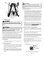
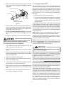
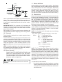
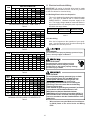
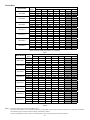
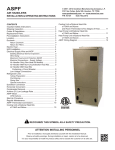
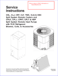
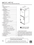
7.2 Horizontal Left Installation
6.4 Clearances
No field modifications are permissible for this application.
The unit clearance from a combustible surface may be
0". However, service clearance must take precedence.
A minimum of 24" in front of the unit for service clearance is required. Additional clearance on one side or
top will be required for electrical wiring connections. Consult all appropriate regulatory codes prior to determining
final clearances. When installing this unit in an area that
may become wet (such as crawl spaces), elevate the
unit with a sturdy, non-porous material. In installations
that may lead to physical damage (i.e. a garage) it is
advised to install a protective barrier to prevent such damage. Always install units such that a positive slope in condensate line (1/4" per foot) is allowed.
The bottom right drain connection is the primary drain for
this application and condensate drain line must be attached to this drain connection. The top connection of
the three drain connections on the drain pan must remain plugged for this application. The bottom left drain
connection is for the secondary drain line (if used).
7.3 Downflow Installation
IMPORTANT NOTE: To prevent the coil pan from “sweating”, the DPI accessory insulation kit must be used when
performing this conversion. The DPI kit is not supplied
with this product and is to be purchased separately. See
Table 1 for the correct DPI kit. Follow the instructions
provided in the kit for appropriate installation.
6.5 Horizontal Applications
If installed above a finished living space, a secondary
drain pan (as required by many building codes), must be
installed under the entire unit and its condensate drain
line must be routed to a location such that the user will
see the condensate discharge.
7
MODEL LIST FOR DRAIN PAN INSULATION KITS
DPI-B
DPI-C
DPI-D
Insulation Kit
Insulation Kit
Insulation Kit
Installation Location
NOTE: These air handlers are designed for indoor installation only.
The ARUF**14**/ARPT**14** product line may be installed
in one of the upflow, downflow, horizontal left or horizontal
right orientations as shown in Figures 1, 2, 3 and 4. The unit
may be installed in upflow or horizontal left orientation as
shipped (refer to specific sections for more information). Field
modifications are necessary to convert to downflow or horizontal right as indicated in below sections.
ARUF18B14**
ARUF36C14**
ARUF48D14**
ARUF24B14**
ARUF42C14**
ARUF60D14**
ARUF30B14**
ARPT36C14**
ARPT36D14**
ARPT18B14**
ARPT42D14**
ARPT24B14**
ARPT48D14**
ARPT30B14**
ARPT60D14**
DOWNFLOW INSULATION KIT
Table 1
Refer to Figure 5 and 6 for the location of the components referenced in the following steps.
7.1 Upflow Installation
No field modifications are mandatory however to obtain
maximum rated efficiency, the horizontal drip shield must
be removed. Without removal of the horizontal drip shield,
performance will be reduced by up to a few percentage
points.
1. Before inverting the air handler, remove blower access
panel and coil access panel. The coil access panel and
tubing panel may remain screwed together during this
procedure. Remove and retain the seven (7) screws securing the coil access panel to the cabinet and the six
(6) screws securing the blower access panel to the cabinet.
Drip Shield Removal: Refer to Figure 9, remove the two
(2) screws that secure the drip shield support brackets to
the condensate collectors (one screw per side). Remove
the two (2) screws that secure the drip shield to the drain
pan. The drip shield and drip shield brackets may now
be removed.
2. Slide the coil assembly out using the drain pan to pull
the assembly from the cabinet.
NOTE: DO NOT USE MANIFOLDS OR FLOWRATOR
TO PULL THE COIL ASSEMBLY OUT. FAILURE TO
DO SO MAY RESULT IN BRAZE JOINT DAMAGE
AND LEAKS.
The bottom left drain connection is the primary drain for
this application and condensate drain line must be attached to this drain connection. The top connection of
the three drain connections on the drain pan must remain plugged for this application. The bottom right drain
connection is for the secondary drain line (if used).
3. Referring to Figure 9, remove the two (2) screws that
secure the drip shield support brackets to the condensate collectors (one screw per side). Remove the (2)
two screws that secure the drip shield to the drain pan.
The drip shield and drip shield brackets may now be
removed.
4. Removal of the center support is required on units with
21" wide cabinet. Remove and retain the two (2) screws
that secure the center support to the cabinet. Remove
the center support.
4