1
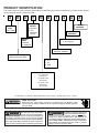
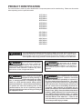
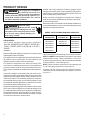
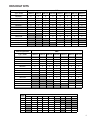
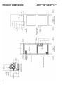
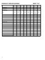
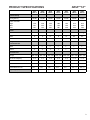
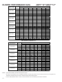
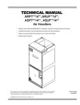
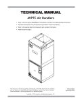
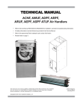
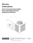
TECHNICAL MANU
AL
MANUAL
ARUF**14** & ARPT**14**
Air Handlers
• Refer to Service Manual RS6200006 for installation, operation & troubleshooting information.
• All safety information must be followed as provided in the Service Manual.
• Refer to the appropriate Parts Catalog for part number information.
• Models listed on page 3.
This manual is to be used by qualified, professionally trained HVAC technicians only. Goodman
does not assume any responsibility for property damage or personal injury due to improper
service procedures or services performed by an unqualified person.
Copyright © 2012 Goodman Company, L.P.
RT6121003
April 2012
PRODUCT IDENTIFICATION
The model number is used for positive identification of component parts used in manufacturing. Please use this number
when requesting service or parts information.
A
R
U
F
18
B
1
4
EXPANSION
DEVICE:
F: Flowrater
T: TXV
(Expansion
Device)
PRODUCT
TYPE:
A: Air Handler
A
A
MINOR
REVISION*
MAJOR
REVISION*
CABINET
FINISH:
P: Painted
U: Unpainted
REFRIGERANT CHARGE:
4: R-410A only
ELECTRICAL:
1: 208-230V/1ph/60Hz
APPLICATION:
R: Multi-Position PSC Motor
CABINET WIDTH
B: 17.5"
C: 21"
D: 24.5"
NOMINAL CAPACITY RANGE:
18: 1-1/2 Tons
24: 2 Tons
30: 2-1/2 Tons
36: 3 Tons
42: 3-1/2 Tons
48: 4 Tons
60: 5 Tons
All Airhandlers use DIRECT DRIVE MOTORS. Power supply is AC 208-230v, 60 hz, 1 phase.
WARNING
HIGH VOLTAGE!
Disconnect ALL power before servicing or installing this unit. Multiple power
sources may be present. Failure to do so may cause property damage, personal
injury or death.
Goodman will not be responsible
for any injury or property damage
arising from improper service or service procedures. If
you install or perform service on this unit, you assume
responsibility for any personal injury or property damage
which may result. Many jurisdictions require a license to
install or service heating and air conditioning equipment.
WARNING
2
Installation and repair of this unit
should be performed ONLY by individuals meeting the requirements of an "entry level technician", at a minimum, as
specified by the Air-Conditioning, Heating, and Refrigeration Institute (AHRI). Attempting to install or repair this
unit without such background may result in product
damage, personal injury or death.
WARNING
PRODUCT IDENTIFICATION
The model number is used for positive identification of component parts used in manufacturing. Please use this number
when requesting service or parts information.
ARPT18B14**
ARPT24B14**
ARPT30B14**
ARPT36C14**
ARPT36D14**
ARPT42D14**
ARPT48D14**
ARPT60D14**
ARUF18B14**
ARUF24B14**
ARUF30B14**
ARUF36C14**
ARUF42D14**
ARUF48D14**
ARUF60D14**
WARNING
The United States Environmental Protection Agency (“EPA”) has issued various regulations regarding the introduction and disposal of refrigerants introduced into this unit. Failure to follow
these regulations may harm the environment and can lead to the imposition of substantial fines.
These regulations may vary by jurisdiction. Should questions arise, contact your local EPA office.
Do not connect or use any device
that is not design certified by
Goodman for use with this unit.
Serious property damage, personal injury, reduced unit
performance and/or hazardous conditions may result
from the use of such non-approved devices.
To prevent the risk of property
damage, personal injury, or death,
do not store combustible materials or use gasoline or
other flammable liquids or vapors in the vicinity of this
appliance.
When installing or servicing this
equipment, safety clothing, including hand and eye protection, is strongly advised. If installing this equipment in an area that has special safety requirements (hard hats etc.), observe these requirements.
To protect the unit when brazing close to the
painted surfaces, the use of a quenching cloth is
strongly advised to prevent scorching or marring of
the equipment finish.
The unit MUST have an uninterrupted, unbroken electrical
ground to minimize the possibility of personal injury if an electrical fault should occur. The electrical ground circuit may consist of an appropriately
sized electrical wire connecting the ground lug in
the unit control box to the building electrical service panel. Other methods of grounding are permitted if performed in accordance with the “National
Electric Code” (NEC)/“American National Standards
Institute” (ANSI)/“National Fire Protection Association” (NFPA) 70 and local/state codes. In Canada,
electrical grounding is to be in accordance with the
Canadian Electric Code CSA C22.1. Failure to observe this warning can result in electrical shock that
can cause personal injury or death.
WARNING
WARNING
WARNING
WARNING
3
PRODUCT DESIGN
If this appliance is installed in
an enclosed area such as a
garage or utility room with any
carbon monoxide (CO) producing appliance (i.e.
automobile, furnace, water-heaters, etc.), ensure
the area is properly ventilated.
WARNING
WARNING
HIGH VOLTAGE
Disconnect ALL power
before servicing or installing this unit. Multiple power sources may be present. Failure
to do so may cause property damage, personal injury or death.
Heating and cooling equipment located in garages, which
may generate a glow, spark or flame capable of igniting flammable vapors, must be installed with the ignition source at
least 18"[46cm] above the floor level.
When more than one appliance is installed in a building it
shall be permanently identified as to the area or space serviced by the equipment.
When this product is installed in the downflow installation in
an unconditioned space, remove the horizontal drain pan and
install the following insulation kit.
MODEL LIST FOR DRAIN PAN INSULATION KITS
DPI-B
Insulation Kit
DPI-C
Insulation Kit
DPI-D
Insulation Kit
ARUF18B14**
ARUF36C14**
ARUF48D14**
ARUF24B14**
ARUF42C14**
ARUF60D14**
ALL AIR HANDLERS USE DIRECT DRIVE MOTORS. POWER SUPPLY IS 208-230 V, 60 HZ, 1
PHASE.
ARUF30B14**
ARPT36C14**
ARPT36D14**
Installation
AIR HANDLERS
See Air Handler Specification Sheet for Proper Combinations.
ARPT18B14**
ARPT42D14**
ARPT24B14**
ARPT48D14**
ARPT30B14**
ARPT60D14**
Before installing this appliance insure that it is properly sized
and adequate power is available.
This kit is used to prevent sweating on the vertical drain pan.
This appliance can be installed in the vertical or right horizontal position without modification. The horizontal left and
downflow positions require product modification.
ARPT and ARUF air handlers are multi-position, multi-speed
with direct drive motors. They are available in 1 1/2 to 5 ton
sizes with optional 3 kW to 21kW electric heat kits available
for field installation. (See following note.)
This product is designed for zero inches (0 inches) clearance; however, adequate access for service or replacement
must be considered without removing permanent structure.
This unit can be installed on a platform when deemed necessary.
In an attic installation a secondary drain pan must be provided by the installer and placed under the entire unit with a
separate drain line properly sloped and terminated in an area
visible to the owner. This secondary drain pan is required in
the event that there is a leak or main drain blockage. Closed
cell insulation should be applied to the drain lines in unconditioned spaces where sweating may occur.
Appliances installed in garages, warehouses or other areas
where they may be subjected to mechanical damage must
be suitably guarded against such damage by installing behind protective barriers, being elevated or located out of the
normal path of vehicles. When installed on a base, the base
must also be protected by similar means.
4
NOTE: Factory-sealed to achieve a 2% or less leakage rate
at 1.0" water gauge external duct static pressure.
Complies with the Factory-sealed Air Handling Credit as
listed in the 2001 Florida Building Code, Chapter 13, Section
610.2.A.2.1.
HKS HEAT KITS
ARPT
Heat Kit Applications
Type / model
18B14-A*
24B14-A*
30B14-A*
36C14-A*
36D14-A*
42D14-A*
48D14-A*
60D14-A*
HKSX03XC*
HKSX05XC*
HKSX06XC*
HKSX08XC*
HKSX10XC*
HKSC05XC*
HKSC08XC*
HKSC10XC*
HKSC15XA*
HKSC15XB*
HKSC19CA*
HKSC19CB*
HKSC20DA*
HKSC20DB*
X
X
X
X
X
X
X
X
X
X
X
X
X
X
X
X
X
X
X
X
X
X
X
X
X
X
X
X
X
X
X
X
X
X
X
X
X
X
X
X
X
X
X
X
X
X
X
X
X
X
X
X
X
X
X
X
X
X
X
X
X
X
X
X
X
X
X
X
X
X
X
X
X
X
X
X
X
X
X
X
X
X
X
X
X
X
* Revision level that may or may not be designated
Refer to the minimum airflow requirements for each of the heat kits.
ARUF
Heat Kit Applications
Type / model
18B14-A*
24B14-A*
30B14-A*
36C14-A*
42C14-A*
48D14-A*
60D14-A*
HKSX03XC*
X
X
X
X
X
X
X
HKSX05XC*
X
X
X
X
X
X
X
HKSX06XC*
X
X
X
X
X
X
X
HKSX08XC*
X
X
X
X
X
X
X
HKSX10XC*
X
X
X
X
X
X
X
HKSC05XC*
X
X
X
X
X
X
X
HKSC08XC*
X
X
X
X
X
X
X
HKSC10XC*
X
X
X
X
X
X
X
HKSC15XA*
X
X
X
X
X
HKSC15XB*
X
X
X
X
X
HKSC19CA*
X
X
HKSC19CB*
X
X
HKSC20DA*
X
X
HKSC20DB*
X
X
* Revision level that may or may not be designated
Refer to the minimum airflow requirements for each of the heat kits.
HEATER (kW)
*ARUF
ARPT
3
5
6
8
10
18
715
715
715
715
950
24
715
715
715
715
950
30
715
715
715
715
875
875
36
1170
1170
1170
1170
1345
1345
42
1170
1170
1170
1170
1345
1345
48
1590
1590
1590
1590
60
1590
1590
1590
1590
15
19
20
25
1715
1715
1715
1715
1715
1715
Minimum CFM required for Heater Kits
5
PRODUCT DIMENSIONS
6
ARPT**14**/ARUF**14**
PRODUCT DIMENSIONS
ARPT**14**/ARUF**14**
Model
A
B
C
D
E
F
G
H
ARPT18B14*
45
16 2/5
17 1/2
18
15
14 1/6
8 7/9
12
ARPT24B14*
45
16 2/5
17 1/2
18
15
14 1/6
8 7/9
12
ARPT30B14*
45
16 /5
17 /2
1
18
15
14 /6
8 /9
7
12
ARPT36C14*
49
20
21
20
17
17 2/3
10 1/2
12 2/5
ARPT36D14*
58
23 1/3
24 1/2
28 7/9
25 7/9
21 1/6
12 2/7
12 2/5
ARPT42D14*
58
23 /3
24 /2
28 /9
25 /9
21 /6
12 /7
12 /5
ARPT48D14*
58
23 1/3
24 1/2
28 7/9
25 7/9
21 1/6
12 2/7
12 2/5
ARPT60D14*
58
23 1/3
24 1/2
28 7/9
25 7/9
21 1/6
12 2/7
12 2/5
Model
A
B
C
D
E
F
G
H
ARUF18B14*
45
16 2/5
17 1/2
18
15
14 1/6
8 7/9
12
ARUF24B14*
45
16 /5
17 /2
18
15
14 /6
8 /9
7
12
ARUF30B14*
45
16 2/5
17 1/2
18
15
14 1/6
8 7/9
12
ARUF36C14*
49
20
21
20
17
17 /3
10 /2
12 /5
ARUF42C14*
49
20
21
20
17
17 2/3
10 1/2
12 2/5
ARUF48D14*
58
23 1/3
24 1/2
28 7/9
25 7/9
21 1/6
12 2/7
12 2/5
ARUF60D14*
58
23 1/3
24 1/2
28 7/9
25 7/9
21 1/6
12 2/7
12 2/5
2
1
1
7
7
1
1
2
2
Dimensions are in inches.
2
1
1
2
1
2
Dimensions are in inches.
7
PRODUCT SPECIFICATIONS
ARPT**14**
ARPT
18B14*
ARPT
24B14*
ARPT
30B14*
ARPT
36C14*
ARPT
36D14*
ARPT
42D14*
ARPT
48D14*
ARPT
60D14*
18,000
24,000
30,000
36,000
36,000
42,000
48,000
60,000
1065
825
560
1065
825
560
1020
775
565
1445
1300
1175
1705
1485
1140
1810
1555
1350
1845
1495
1280
2080
1865
1505
9½"
9½"
9½"
10?"
10?"
10?"
15
11 15/16 "
Width
6"
6"
6"
8"
10?"
10?"
10?"
10?"
Coil Drain Connect FPT
¾"
¾"
¾"
¾"
¾"
¾"
¾"
¾"
Liquid
?"
?"
?"
?"
?"
?"
?"
?"
Suction
¾"
¾"
¾"
?"
?"
?"
?"
?"
Nominal Ratings
Cooling (Btu/h)
Airflow Rate CFM *
High
Med
Low
Blower
Diameter
11
/16 "
Refrigerant Line
Connection Size
Electrical Data
Voltage
Min Circuit Ampacity
Max. Overcurrent Device (amps)
Min. / Max VAC
Blower Motor FLA/ HP
Ship Weight (lbs)
*Airflow rate @.3 static
8
208 / 230 208 / 230 208 / 230 208 / 230 208 / 230 208 / 230 208 / 230 208 / 230
3/3
3/3
3/3
4/4
4/4
5/5
5/5
6/6
15 / 15
15 / 15
15 / 15
15 / 15
15 / 15
15 / 15
15 / 15
15 / 15
197 / 253 197 / 253 197 / 253 197 / 253 197 / 253 197 / 253 197 / 253 197 / 253
1.9 / ?
1.9 / ?
1.9 / ?
3.1 / ?
3.0 / ½
3.5 / ½
3.5/ ½
4.6 / ¾
100
100
105
118
155
155
167
167
PRODUCT SPECIFICATIONS
ARUF**14**
ARUF
18B14*
ARUF
24B14*
ARUF
30B14*
ARUF
36C14*
ARUF
42C14*
ARUF
48D14*
ARUF
60D14*
18,000
24,000
30,000
36,000
42,000
48,000
60,000
1045
835
565
1045
835
565
1020
775
565
1385
1235
980
1465
1290
1000
1810
1555
1350
2125
1885
1455
9½"
9½"
9½"
10?"
10?"
10?"
11 15 /16"
Width
6"
6"
6"
8"
8"
10?"
10?"
Coil Drain Connect FPT
¾"
¾"
¾"
¾"
¾"
¾"
¾"
Liquid
?"
?"
?"
?"
?"
?"
?"
Suction
¾"
¾"
¾"
¾"
?"
?"
?"
208 / 230
208 / 230
208 / 230
208 / 230
208 / 230
208 / 230
208 / 230
3/3
3/3
3/3
4/ 4
4/4
5/5
6/6
15 / 15
15 / 15
15 / 15
15 / 15
15 / 15
15 / 15
15 / 15
197 / 253
197 / 253
197 / 253
197 / 253
197 / 253
197 / 253
197 / 253
1.9 / ?
1.9 / ?
1.9 / ?
3.0 / ?
3.1 / ?
3.5 / ½
4.6 / ¾
98
98
103
115
117
154
154
Nominal Ratings
Cooling (Btu/h)
Airflow rate CFM*
High
Med
Low
Blower
Diameter
Refrigerant Line
Connection Size
Electrical Data
Voltage
Min Circuit Ampacity
Max. Overcurrent Device (amps)
Min. / Max VAC
Blower Motor FLA/ HP
Ship Weight (lbs)
*Airflow rate @.3 static
9
BLOWER PERFORMANCE DATA
Model Number
Blower
Speed
ARPT18B14
High
Medium
Low
ARPT**14**/ARUF**14**
Static Pressure (in w.c)
0.1
1185
900
630
0.2
1125
850
605
0.3
1065
825
560
0.4
1010
785
525
0.5
985
715
495
0.6
910
670
445
0.7
780
610
355
Low
1185
900
630
1125
850
605
1065
825
560
1010
785
525
985
715
495
910
670
445
780
610
355
ARPT30B14
High
Medium
Low
1145
870
615
1085
820
585
1020
775
565
950
745
535
900
705
490
845
655
435
765
580
345
ARPT36C14
High
Medium
Low
1580
1385
1260
1515
1350
1205
1445
1300
1175
1395
1250
1105
1345
1170
1040
1240
1095
975
1155
1005
865
High
Medium
Low
High
Medium
Low
High
Medium
Low
High
Medium
Low
1815
1580
1220
1770
1525
1180
1705
1485
1140
1640
1420
1085
1555
1350
1030
1450
1275
950
1355
1165
865
1990
1655
1480
1915
1605
1420
1810
1555
1350
1765
1480
1290
1690
1295
1185
1585
1200
1100
1435
1060
1045
1960
1600
1395
1905
1545
1340
1845
1495
1280
1780
1435
1220
1715
1360
1150
1645
1290
1090
1570
1215
1020
2205
1985
1600
2140
1935
1555
2080
1865
1505
2010
1815
1455
1945
1755
1405
1870
1695
1345
1795
1635
1295
ARPT24B14
ARPT36D14
ARPT42D14
ARPT48D14
ARPT60D14
High
Medium
AIRFLOW DATA (CFM) ARPT**14**
ARUF18B14
High
Medium
Low
0.1
1150
890
640
0.2
1095
855
605
Static Pressure (in w.c)
0.3
0.4
0.5
1045
1025
950
835
775
715
565
530
485
0.6
865
665
440
0.7
775
605
360
ARUF24B14
High
Medium
Low
1150
890
640
1095
855
605
1045
835
565
1025
775
530
950
715
485
865
665
440
775
605
360
ARUF30B14
High
Medium
Low
1145
870
615
1085
820
585
1020
775
565
950
745
535
900
705
490
845
655
435
765
580
345
High
Medium
Low
High
Medium
Low
High
Medium
Low
High
Medium
Low
1485
1300
1040
1435
1270
1015
1385
1235
980
1345
1195
930
1275
1130
865
1205
1060
790
1125
955
705
1580
1395
1095
1530
1340
1045
1465
1290
1000
1400
1235
950
1330
1170
895
1255
1095
820
1165
1000
725
1990
1655
1480
1915
1605
1420
1810
1555
1350
1765
1480
1290
1690
1295
1185
1585
1200
1100
1435
1060
1045
2235
2030
1615
2175
1970
1535
2125
1885
1455
2050
1800
1355
1960
1690
1270
1825
1600
1185
1720
1495
1090
Model Number
Blower
Speed
ARUF36C14
ARUF42C14
ARUF48D14
ARUF60D14
AIRFLOW DATA (CFM) ARUF**14**
Notes: • Airflow data indicated is at 230V without air filter in place.
• The chart is for information only. For satisfactory operation, external static pressure must not exceed value shown on rating plate. The
shaded area indicates ranges in excess of maximum design external static pressure.
• Use the CFM adjustment factors of 0.98 for horizontal left and 0.96 for horizontal right & downflow orientations.
10
ARPT**14**/ARUF**14**
WIRING DIAGRAMS
HIGH VOLTAGE!
DISCONNECT ALL POWER BEFORE SERVICING OR INSTALLING THIS
UNIT. MULTIPLE POWER SOURCES MAY BE PRESENT. FAILURE TO
DO SO MAY CAUSE PROPERTY DAMAGE, PERSONAL INJURY OR DEATH.
FL
FL
FL
FL
HTR2 TL
FL
HTR1 TL
FL
HTR1 TL
FL
FL
HTR1 TL
RD
BK
BK
BK
HTR2 TL
FL
RD
BK
BK
2
BK
HTR2 TL
RD
HTR3 TL
FL
1
HTR1 TL
YL
HTR3 TL
1
BK
HTR4 TL
1
BL
BK
RD
2
PU
BK
3
BL
YL
PU
4
M1
R
BK
RD
M1
M3
4
M2
M4
5
M4
WH
4
R2
RD
5
BR
M2
M3
M4
M5
M7
M6
M8
R1
RD
WH
3
RD
BL
R2
BR
4
5
BK
6
BK
6
RD
WH
6
7
7
BK
8
M1
YL
M2
RD
BK
RD
BK RD
BK
BK
7
BK
M2
BL
BL
RD
BL
M1
R1
6
BK
RD
M3
2
PU
3
BL
M1
R
WH
PU
3
1
2
YL
BK
BL
5
M2
RD
RD
7
YL
8
RD
YL
BK
8
RD
9
BL
BK
9
8
RD
9
9
L1
L2
L1
ONE (1) ELEMENT ROWS
L2
L1
TWO (2) ELEMENT ROWS
L2
L1
L2
THREE (3) ELEMENT ROWS
L1
L2
L1
L2
FOUR (4) ELEMENT ROWS
NOTE: WHEN INSTALLING HEATER KIT, ENSURE SPEED TAP IS NOT BELOW MINIMUM BLOWER SPEED (MBS) SPECIFIED FOR THE AIR HANDLER/HEATER KIT
COMBINATION ON THIS UNITS SERIAL PLATE. AFTER INST ALLING OPTIONAL HEAT KIT, MARK A "X" IN THE
PROVIDED ABOVE. MARK ACCORDING TO THE
NUMBER OF HEATER ELEMENT ROWS INSTALLED. NO MARK INDICATES NO HEAT KIT INSTALLED. 5 ELEMENT ROWS DATA SUPPLIED WITH HEATER KIT.
SEE NOTE 2
BL
L1
L2
BK
RD
PLF
1
2
3
4
5
6
7
8
9
PLM
1
2
3
4
5
6
7
8
9
BK
RD
PU
BL
BR
WH
TERMINAL BLOCK SHOWN
FOR 50HZ MODELS ONLY
RD GR WH
EQUIPMENT GROUND
USE COPPER WIRE
208/240 VOLTS
BR
GRD
SR
L1
L2
PLF 2
1 PLF
1 PLM
3
2
EM
RC
SEE
NOTE 4
HI
BR
LO
WH
PLM
1
2
3
4
24V
5
M1
NO
NC
EBTDR
M2
COM
SEE NOTE 1
TR
C
EBTDR R
GR
RD
G
BL
COM
K1
SPEEDUP
6
C
2
1
3
RD
240
5
24V
BL
BL
M2
COMPONENT CODE
RD
BK
COPPER POWER SUPPLY
(SEE RATING PLATE)
USE MIN. 75°C FIELD WIRE
SEE
NOTE 3
THREE SPEED MOTOR WIRING
(SELECT MODELS ONLY)
SEE NOTE 3
RD
PU
NOTES:
(COM) RD
(M2) BL
(TR 1)
BK
LOW
MEDIUM
(M1) BK
IF REPLACEMENT OF THE ORIGINAL WIRES
SUPPLIED WITH THIS ASSEMBLY IS NECESSARY
USE WIRE THAT CONFORMS TO THE
NATIONAL ELECTRIC CODE.
EM
RC
SR
R
EBTDR
HIGH
PU
BR
PU
RC
RC
BR
EM
3 SPEED
EM
BR
GR
BL
WH BR
GR
BK BLACK
PU
RD RED
YL YELLOW BR
WH
BL BLUE
4
NC
M1
G
4 PLF
COLOR CODE
TR
PU
5
EBTDR
SEE NOTE 1
RD
RD
NO
K1
C
BL
RD
PU
EBTDR
R
XFMR-R
XFMR-C
RD
BK
SEE NOTE 5
WIRING CODE
GREEN
PURPLE
BROWN
WHITE
FACTORY WIRING
HIGH VOLTAGE
LOW VOLTAGE
FIELD WIRING
HIGH VOLTAGE
LOW VOLTAGE
EVAPORATOR MOTOR
TR
RUN CAPACITOR
PLF
STRAIN RELIEF
PLM
FL
RELAY
TL
ELECTRONIC BLOWER TIME
DELAY RELAY
HTR
TRANSFORMER
FEMALE PLUG CONNECTOR
MALE PLUG CONNECTOR
FUSE LINK
THERMAL LIMIT
HEAT ELEMENTS
1) RED WIRES TO BE ON TRANSFORMER TERMINAL "3" FOR 240 VOLTS
AND ON TERMINAL "2" FOR 208 VOLTS.
2) SEE COMPOSITE WIRING DIAGRAMS IN INSTALLATION INSTRUCTIONS
FOR PROPER LOW VOLTAGE WIRING CONNECTIONS.
3) CONFIRM SPEED TAP SELECTED IS APPROPRIATE FOR APPLICATION.
IF SPEED TAP NEEDS TO BE CHANGED, CONNECT APPROPRIATE
MOTOR WIRE (RED FOR LOW, BLUE FOR MEDIUM,AND BLACK FOR
HIGH SPEED) ON "COM" CONNECTION OF THE EBTDR.
INACTIVE MOTOR WIRES SHOULD BE CONNECTED TO "M1 OR M2"
ON EBTDR.
4) BROWN AND WHITE WIRES ARE USED WITH HEAT KITS ONLY.
5) EBTDR HAS A 7 SECOND ON DELAY WHEN "G" IS ENERGIZED
AND A 65 SECOND OFF DELAY WHEN "G" IS DE-ENERGIZED.
0140A00058-B
Wiring is subject to change. Always refer to the wiring diagram on the unit for the most up-to-date wiring.
11