1
HP Performance Optimized Datacenter 40c G2
Site Preparation and Requirements Guide
Abstract
This document provides site preparation guidance for the HP Performance Optimized Datacenter 40c G2 (HP POD 40c G2).
Part Number: 695162-002
August 2012
Edition: 2
© Copyright 2012 Hewlett-Packard Development Company, L.P.
The information contained herein is subject to change without notice. The only warranties for HP products and services are set forth in the express
warranty statements accompanying such products and services. Nothing herein should be construed as constituting an additional warranty. HP shall
not be liable for technical or editorial errors or omissions contained herein.
Contents
Overview ..................................................................................................................................... 5
About this document .................................................................................................................................. 5
Safety and NEC compliance ....................................................................................................................... 5
Site assessment ......................................................................................................................................... 6
Site preparation ........................................................................................................................................ 6
Site safety and security .............................................................................................................................. 6
Fire detection and suppression .................................................................................................................... 6
HP POD 40c G2 capacities ........................................................................................................... 7
HP POD 40c G2 capacity limitations ........................................................................................................... 7
Electrical power capacities (critical IT power) ...................................................................................... 7
Mechanical cooling capacities .......................................................................................................... 7
Overall system capacities ........................................................................................................................... 7
Site requirements .......................................................................................................................... 8
Site pad ................................................................................................................................................... 8
HP POD 40c G2 weight............................................................................................................................. 8
Dimensions and clearances ........................................................................................................................ 8
Safety and clearance area.............................................................................................................. 10
Future expansions .......................................................................................................................... 11
Grounding requirements ........................................................................................................................... 11
Utilities ................................................................................................................................................... 12
Humidifier water supply ................................................................................................................. 12
Drainage ...................................................................................................................................... 13
Chilled water supply ...................................................................................................................... 13
Piping materials ............................................................................................................................ 15
Power infrastructure installation ................................................................................................................. 15
Site electrical system ...................................................................................................................... 15
Electrical power system configuration ............................................................................................... 15
Transformers and switchboards ....................................................................................................... 16
Supported facility connections ...................................................................................................... 17
Environmental control system .................................................................................................................... 17
Additional POD connections ..................................................................................................................... 17
Connection portals .................................................................................................................................. 17
Demarcation box .................................................................................................................................... 18
Fire box ................................................................................................................................................. 19
Humidifier .............................................................................................................................................. 20
HP POD 40c G2 security ......................................................................................................................... 20
Fire, safety, and security notifications ......................................................................................................... 20
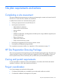
Environmental considerations ....................................................................................................... 22
Environmental risks .................................................................................................................................. 22
Cold weather .......................................................................................................................................... 22
Areas prone to lightning or power surges ................................................................................................... 22
Seismic activity ....................................................................................................................................... 22
Site plan requirements and actions ............................................................................................... 23
Contents
3
Completing a site assessment .................................................................................................................... 23
HP Site Preparation Drawing Package ....................................................................................................... 23
Zoning and permit requirements ................................................................................................................ 23
Project coordination................................................................................................................................. 23
Site planning .......................................................................................................................................... 24
HP POD 40c G2 installation ........................................................................................................... 24
Appendix A: HP site assessment ................................................................................................... 27
HP POD 40c G2 site assessment checklist .................................................................................................. 27
Appendix B: Preparing for delivery ............................................................................................... 31
Pre-delivery tasks ..................................................................................................................................... 31
Installation prerequisites ................................................................................................................. 31
HP POD 40c G2 site readiness checklist .................................................................................................... 31
Appendix C: Regulatory compliance notices .................................................................................. 35
HP POD 40c G2 regulatory compliance ..................................................................................................... 35
Regulatory compliance identification numbers ................................................................................... 35
Federal Communications Commission notice ..................................................................................... 35
Modifications ................................................................................................................................ 35
Cables ......................................................................................................................................... 36
Canadian notice (Avis Canadien) .................................................................................................... 36
Glossary .................................................................................................................................... 37
Documentation feedback ............................................................................................................. 39
Index ......................................................................................................................................... 40
Contents
4
Overview
About this document
This document outlines the site preparation requirements for an HP Performance Optimized Datacenter 40c
G2. The customer must provide a qualified architectural or consulting engineering team to generate
site-specific documents for each HP POD 40c G2 installation, including final site drawings. The customer's
site installation design must comply with all local and national regulations, ordinances, codes, and the
specifications listed in this document.
Safety and NEC compliance
The HP POD 40c G2 is certified to UL 69050-1/IEC 60950-22 as a Modular Data Center Information
Technology Product and classified according to the National Electric Code NFPA 70 in accordance with
NEC (NA) and IEC (EMEA and APJ). Relevant parts of UL1995 are applied to the air handling features of the
product. For more information, see "HP POD 40c G2 regulatory compliance (on page 35)."
The HP POD 40c G2 is not suitable for long-term human occupancy. The HP POD 40c G2 has service access
areas for periodic maintenance and service. These areas must be used only by owner-authorized personnel
who are trained in the maintenance and service of the HP POD 40c G2 components.
IMPORTANT: Before installing the HP POD 40c G2, consult your local AHJ for applicable codes
and to review site-specific location guidelines. If needed, obtain any necessary permits.
Additional considerations for safety and NEC compliance are as follows:
•
The HP POD 40c G2 is listed as an Information Technology Equipment Product to UL 60950.
•
The HP POD 40c G2 is evaluated as a "non-inhabitable product" that provides "service access" areas
for customer-authorized, qualified, and trained service personnel.
•
The electrical connections of the HP POD 40c G2 are evaluated as feeder connections for connection
to an existing facility, and are not suitable as "service entrance" for connection to the utility.
•
The HP POD 40c G2 is designed for stationary installation outdoors in a Pollution Degree 3
environment, in restricted access locations, with field wiring terminals provided for permanent supply
connections.
•
The HP POD 40c G2 meets the following ratings:
Feature
Specification
Category
Rated Overvoltage Category III
Protection
Surge protection device
Class
Class1
Ambient temperature
2°C to 54°C (35.6°F to 129.2°F)
Relative humidity
0% to 100% humidity
•
As part of the overall certification, relevant sections of the International Building Code have been
applied as part of the design and evaluation. The current design supports wind loads up to 90 mph.
Overview 5
Site assessment
HP requires a detailed site assessment prior to planning and preparing the customer site location for the HP
POD 40c G2. Consult with HP to schedule a site assessment.
Site preparation
Site preparation must be complete prior to the POD delivery to ensure a timely installation and
commissioning. The site must meet all pad, power, and chilled water requirements.
Site safety and security
Each customer site must have its own standard safety and security requirements. The HP Program Managers
work with the customer to ensure adherence to the appropriate precautions. HP is not responsible for
determining or enforcing safety or security requirements. The customer must conduct all health and safety
evaluations of the HP POD 40c G2, only using HP as a support mechanism.
Fire detection and suppression
The fire suppression system, supplied as an optional component of the HP POD 40c G2, is a "Manufacturer
Designed" system specifically for this HP product, in compliance with national standards.
The HP standard suppression system includes a Novec 1230 clean agent system. However, if the customer
or local AHJ requires specific modifications or a replacement, HP can assist in these actions at the expense
of the customer.
HP does not certify that the fire suppression system installed in the HP POD 40c G2 meets all local and
jurisdictional requirements. The customer is responsible for the following actions as related to the fire
suppression system:
•
Verifying that the POD suppression system meets local codes, including specific local requirements for
initial and periodic inspections.
•
Arranging for and receiving all required local permits, including initial commissioning as well as
standard and repair maintenance.
•
Arranging for the connection of the agent tanks, refilling of tanks, and all system testing, including
pressure tests. All general maintenance of the suppression system must be completed by an authorized
technician.
Additional local requirements are not covered as part of the option price or basic installation and
deployment services, unless specifically included in an executed Statement of Work.
Overview 6
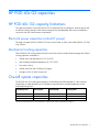
HP POD 40c G2 capacities
HP POD 40c G2 capacity limitations
The capacity limitations for the HP POD 40c G2 are separated into two categories: electrical power and
mechanical cooling capacities. Both of these categories are interdependent and must be considered in
conjunction with the overall customer requirements.
Electrical power capacities (critical IT power)
The electrical system of the HP POD 40c G2 has two main feeds, A and B, each rated at 800 A 415 VAC
Wye 3-Phase.
Mechanical cooling capacities
The HP POD 40c G2 cooling system consists of 6 zones. Each zone includes 2 heat exchangers and 18 fans.
Cooling capacities are based on:
•
Chilled water inlet temperature of 15.6ºC (60ºF)
•
Heat exchanger fluid delta temperature of 5.5ºC (10ºF)
•
Pure water cooling
•
Chilled water flow rate of 908 lpm (240 gpm)
•
Average air flow of 2000 cfm per rack
Overall system capacities
The HP POD 40c G2 overall system capacities are provided in the following table. It is the customer's
responsibility to understand the level of redundancy required for their particular application and its
associated limiting factor.
Redundancy level
Electrical (kW)
Thermal (kW)
Limiting factor
N
—
600
Thermal*
N+1
—
400
Thermal*
2N
576
300
Thermal*
*The thermal limitation factors are described in "Mechanical cooling capacities (on page 7)."
HP POD 40c G2 capacities
7
Site requirements
Site pad
The structural design of the HP POD 40c G2 site pad must be based on the specific weight load of the
complete POD solution with IT installed, as well as any additional equipment. During design calculations, HP
recommends that you provide structural support along the entire perimeter of the POD and use the maximum
allowable POD weight.
Upon installation, the POD structure must be leveled to ≤ 0.5º. Shimming is allowed around the perimeter of
the POD to ensure that the POD remains level.
IMPORTANT: The HP POD 40c G2 is designed for ground level installation. If you install the HP
POD 40c G2 on an elevated surface, verify that the minimum height requirements for circuit
breaker actuators are considered per local and national requirements and electrical codes. The
area in front of the outside panels must include a work platform.
HP POD 40c G2 weight
IMPORTANT: The weight provided is a minimum and an absolute maximum rated weight. The
total weight of the HP POD 40c G2 differs based on the IT equipment and optional components
purchased and installed.
The overall weight might significantly vary depending on the final customer-chosen solution for the HP POD
40c G2. Each site pad must meet the weight requirements of the equipment that is expected to be installed.
The HP POD 40c G2 must be installed on a surface capable of supporting the following weights:
•
HP POD 40c G2 without IT equipment installed—Approximately 16,783 kg (37,000 lb)
•
HP POD 40c G2 with IT equipment installed—Maximum 46,266 kg (102,000 lb)
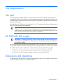
Dimensions and clearances
The selected site for the HP POD 40c G2 must be large enough to install, service, maintain, and have space
for potential growth or expansion with additional PODs.
Site requirements
8
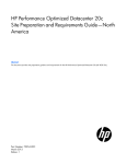
End 1 view clearances shown
Top view keep-out clearances shown (shaded areas indicate required clearances)
Site requirements
9
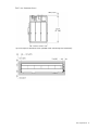
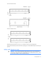
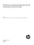
Top view clearances shown
Side view clearances shown
Adequate space around the HP POD 40c G2 is necessary for airflow and cooling purposes.
These minimum clearances provide room for door opening only. Consider additional space as necessary for
your site.
Safety and clearance area
WARNING: Check for electrical distribution and transmission lines in, over, and under the
construction site and maintain a safe working clearance from energized electrical lines. Consult
your local utility company or AHJ for required clearances.
Site requirements
10
Verify the following clearances prior to delivery:
•
•
•
Working distance clearance—Maintain a safe working clearance according to the local utility
company or AHJ for each of the following items:
o
Buildings
o
Fences
o
Gate headers
o
Underground and overhead utilities
Infrastructure clearance
o
Underground power conduits, excluding power, water, and drainage lines connected to the HP
POD 40c G2
o
Underground water lines, excluding power, water, and drainage lines connected to the HP POD
40c G2
o
Underground sewage lines, excluding power, water, and drainage lines connected to the HP POD
40c G2
Traffic clearance
For more information, see the local and national requirements, and site safety requirements.
Future expansions
When selecting a site location, consider future space and accessibility requirements. Adequate space
around the HP POD 40c G2 is necessary for locating additional equipment within close proximity, such as
generators and UPS devices. When installing additional equipment within close proximity to the HP POD
40c G2, consult with HP for site locations.
For specific space requirements, see "Dimensions and clearances (on page 8)."
Grounding requirements
The HP POD 40c G2 structure and internal components are all bonded together. A common grounding
electrode conductor connection point is provided on the utility-end cold aisle.
WARNING: To avoid the risk of personal injury or electric shock, the HP POD 40c G2 must be
properly grounded (earthed) in accordance with local and national requirements.
The following is a list of component requirements for grounding and bonding:
•
Grounding of the HP POD 40c G2 must comply with the requirements of Article 250 of the NEC, NFPA
70-2011 (NA/JPN) and with local and regional regulations (IEC for EMEA and AP).
•
Bonding of the piping systems and any exposed structural steel, installed to support the HP POD 40c
G2, must be in accordance with NEC (NA) and with local and regional regulations (IEC for EMEA and
APJ).
Site requirements
11
Grounding feature
Specification
Grounding electrode
conductor pad
•
•
The grounding electrode conductor connection bus pad is located on the outside of
the HP POD 40c G2 on the cold aisle adjacent to the power cabinet.
The grounding pad must be connected to the grounding electrode system or
building steel in accordance with Article 250 of the NEC or equivalent regional
regulation.
Grounding lugs
•
•
Ground rod system or
ground well
The customer must provide an effective grounding system with a ground rod or a
ground well.
Grounding lugs cannot be attached to any painted surface.
Grounding lugs must be compression-type 2-hole lugs and UL listed specifically for
grounding.
IMPORTANT: Before installing the HP POD 40c G2, consult your local AHJ for applicable codes
and to review site-specific location guidelines. If needed, obtain any necessary permits.
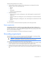
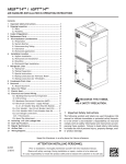
The following figure shows the grounding electrode conductor connection that is located on the cold aisle of
the HP POD 40c G2.
Side view shown
Utilities
Consider the proximity to required utilities, such as power, water, and network connections. While the
required utilities can be brought to nearly any selected site, there is the potential for increased costs and
decreased efficiency when the HP POD 40c G2 is located farther from the utility sources.
For utility clearance information, see "Dimensions and clearances (on page 8)."
Humidifier water supply
The HP POD 40c G2 requires supply water for the humidifier. The supply water must meet the following
requirements.
Requirement
Specification
Pressure
Between 20 and 110 psi, 0.1 and 0.8 MPa
Temperature
Between 1º and 40°C (33º and 104°F)
Minimum flow rate
1.45 lpm (0.12 gpm)
Site requirements
12
Requirement
Specification
Connection
1.9 cm (.75 in) G
Adapter to 1.9 cm (.75 in) FPS
Hardness
No greater than 40°fH (equal to 400 ppm of CaCO3)
Conductivity
100 to 1250 μS/cm
Organic compounds
None
Type of water
Drinking water. Do not use de-mineralized or softened water.
Instant water fill flow
rate
0.6 lpm (0.16 gpm)
Humidifier
For the exact requirements, see the humidifier documentation.
IMPORTANT: If your water is out of range, consult a water quality expert.
IMPORTANT: You must provide a humidification water supply isolation valve that is external to
the HP POD 40c G2.
In addition to the previous requirements, observe the following requirements and recommendations:
•
Do not treat the water with softeners. Softeners can produce foam, which affects the operation of the
unit.
•
Do not use well water, industrial water, water from cooling circuits, or water contaminated by any
chemicals or bacteria.
•
Do not add potential irritants to the water, such as disinfectants or anti-corrosive compounds.
•
The manufacturer recommends installing an in-line filter for the water supply. It is your responsibility to
determine if a filter should be installed, and if so, its location. The filter cannot be installed inside the HP
POD 40c G2 and must be compatible with the type of humidifier that is installed.
For more information, see the HP Performance Optimized Datacenter 40c G2 Maintenance and Service
Guide.
Drainage
Requirement
Location
Specification
Condensate drains
Hot aisle side (2)
3.18 cm (1.25 in) drain line and 26.5 lpm (7 gpm) max
Humidifier drains
Cold aisle side (1)
3.18 cm (1.25 in) drain line and 26.5 lpm (7 gpm) max
Chilled water supply
The following are the water quality requirements and specifications:
•
Closed-loop water must not contain any lime scale deposits or loose debris.
•
The temperature of the chilled water supplied to the HP POD 40c G2 must be 12ºC to 24ºC (55ºF to
75ºF).
CAUTION: Freezing water can cause a blockage and damage to the unit. In outside locations
that are subject to freezing temperatures, an additive such as glycol might be necessary to lower
the freezing point. However, since the heat transfer potential of water with glycol is lower, the HP
POD 40c G2 must be de-rated accordingly.
Site requirements
13
IMPORTANT: The chilled water system piping and heat exchangers must be drained completely,
and then purged using compressed air when storing or transporting at or below freezing
temperatures.
IMPORTANT: Operating the chilled water system at the higher end of the acceptable range
decreases the overall thermal capacity of the POD.
Acceptable water quality specifications
Water must be maintained per the following acceptable water quality standards.
Parameter
Range
pH
8.0–10
Specific conductance at 25ºC (77ºF) 10–2500 µmhos
150–1000 ppm
Alkalinity ("M" as CaCO3)
Sulfur (SO4)
Chloride (Cl)
Hardness (CaCO3)
Calcium hardness (CaCO3)
Magnesium hardness (CaCO3)
0–150 ppm
0–100 ppm
0–350 ppm
0–200 ppm
0–150 ppm
Copper (Cu)
< 0.20 ppm
Iron (Fe)
< 3.0 ppm
Aluminum (Al)
< 0.50 ppm
Sodium (Na)
0–1000 ppm
Silica (SiO2)
0–150 ppm
Zinc (Zn)
< 1.0 ppm
Manganese (Mn)
< 0.1 ppm
Phosphate Ortho- (PO4)
< 3 ppm
Bacteria
< 1000 CFU/ml
Suspended solids
< 10 ppm
If your water is out of range, consult a water quality expert.
The following table describes the chilled water system specifications for the HP POD 40c G2.
Feature
Specification
Facility input temperature to the HP POD
40c G2
12ºC to 24ºC (55ºF to 75ºF)
Working pressure
1,034 kPa (150 psi)
HP POD 40c G2 pressure drop
172.4 kPa (25 psi)
HP POD 40c G2 water flow rate
908.5 lpm (240 gpm)
Chilled water supply and return
connections
•
•
North America—Two 10.16 cm (4 in) ASME B16.5 class #150
flanges
International—Two DIN PN16 DN100 flanges
Site requirements
14
Piping materials
Do not use the following interconnecting piping materials in a closed water system:
•
Oxidizing biocides
•
Aluminum components
•
Brass components with high levels of zinc
•
Non-stainless steel iron components
•
PVC
IMPORTANT: Even though some PVC grade piping materials are designed to handle the
expected water pressure, the use of PVC materials should be reviewed and approved by the
customer site engineers.
Power infrastructure installation
When determining the final location of the power connections, consider the following:
•
Distance between the facility utilities and the location of the transformer and switchboard
•
Distance between the transformer and switchboard and the HP POD 40c G2
•
Distance between the UPS/Generator locations and the HP POD 40c G2 switchboard
•
Requirements for routing electrical feeders (underground or overhead)
The facility power connection must be installed in compliance with local electrical codes and regulations. HP
reference electrical installation design is based on a maximum distance of 15.2 m (50 ft) or line of sight
between the switchboard and the HP POD 40c G2.
Site electrical system
To ensure a complete and safe integration of the HP POD solution with your facility, HP requires that you
complete the following actions for the installed electrical system prior to the installation of the HP POD
solution:
•
Short circuit analysis
•
Arc flash study
•
Circuit breaker coordination study
These actions must be performed for all associated parts of the electrical power train. The majority of the
details and factors required to complete these studies are associated with the existing installed facility
infrastructure.
CAUTION: Failure to complete these studies can cause serious issues with the electrical
integration of the POD into your electrical system.
Electrical power system configuration
A preliminary meeting with the HP POD Electrical Engineering team is necessary to discuss your decision
concerning capacity limitations and the impacts of this decision on the electrical design.
Site requirements
15
A 1N electrical configuration can be achieved by providing all required electrical feeders from a common
power source and from common switchboards, and transformers.
A 2N electrical configuration can be achieved by feeding parallel power paths from independent power
sources, switchboards, and transformers.
IMPORTANT: The required neutral must be provided as part of the 800 A 415VAC Y direct
connection to the HP POD 40c G2.
IMPORTANT: All 3-Phase Wye feeders for the HP POD 40c G2 require that the neutrals and the
equipment grounding conductors remain isolated. Bonding of the two conductors is allowed at
the power source only.
Transformers and switchboards
The input power for the critical IT loads requires a source of 380-415V, 3-Phase Wye power. To achieve this
input power, a custom transformer might be required if it does not already exist at the source. In addition to
the overall loading and KVA size, you must consider the Harmonic Content of the installation when
specifying the K-Factor of the transformer. Alternatively, you can use Harmonic Mitigating Transformers to
passively cancel the harmonics generated by the IT Equipment.
HP offers several power solutions that include automatic transfer switching, UPS backup, transformers and
output distribution switchboards to supply your power needs.
On-site connections might include:
•
Main facility power to the primary side of the transformer
•
Transformer to the switchboard
For connection information, see the HP Site Preparation Drawing Package (on page 23).
Site requirements
16
Supported facility connections
Environmental control system
The ECS developed for the HP water-cooled POD is a stand-alone control system that requires no external
connections with an external site system, BMS, public or private Internet sites, cloud, or wireless system to
properly control the POD operation.
The ECS includes Modbus TCP/IP connections through which a variety of data can be retrieved. These
capabilities enable you to connect, at your expense, with the stand-alone ECS system to monitor the
operating parameters of the POD. It is your responsibility (or your representative's or agent's responsibility)
to integrate this communication capability into any existing BMS or monitoring system.
CAUTION: To ensure that alarm conditions can be identified and resolved, HP recommends that
you remotely monitor all alarm conditions. Failure to monitor the alarm conditions can cause
delays in appropriate action during an alarm condition.
Additional POD connections
The HP POD 40c G2 provides various connection points to your facility. It is your responsibility to facilitate
these connections. HP can make these connections when specifically contracted to deliver these services and
a Scope of Work has been drafted, reviewed, and signed for delivery services. Available POD connections
include the following:
•
•
•
Life safety systems
o
EPO
o
Fire detection
o
Fire suppression
Site communication
o
Phone
o
Security
Networking—IT connections
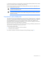
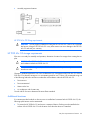
Connection portals
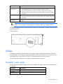
There are networking and connection portals located on the top of the utility-end of the HP POD 40c G2.
These portals are provided to allow the customer to make connections to the HP POD 40c G2.
Each HP POD 40c G2 has 10 portals, which are shown in the following figure and described in the following
table. The connection portal location and configuration might vary, depending on the HP POD 40c G2
model.
Supported facility connections
17
Top view shown
Connection portal
diameter
Connection point
Quantity
8
10.16 cm (4 in) portal Main electrical power
feeds
5.08 cm (2 in) portal Communication connection 2
for all communication
•
•
•
•
ECS
EPO
Fire alarm
Telephone
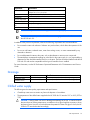
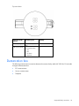
Demarcation box
The following communication connections between the customer facility and the HP POD 40c G2 are made
through the demarcation box:
•
ECS communication
•
Security communication
•
Telephone
Supported facility connections
18
End view shown
You must make the connections between the facility and the HP POD 40c G2. For configuration and
installation instructions, consult with HP.
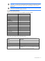
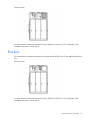
Fire box
The communication connections between the fire system and the HP POD 40c G2 are made through the fire
box.
End view shown
You must make the connections between the facility and the HP POD 40c G2. For configuration and
installation instructions, consult with HP.
Supported facility connections
19
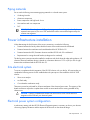
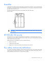
Humidifier
A dedicated water supply and approved drainage is required for the humidifier. For more information about
the humidifier, see the HP Performance Optimized Datacenter 40c G2 Operation and Maintenance Manual
provided with the HP POD 40c G2.
The following image shows the location of the humidifier drain and water supply.
End view shown
IMPORTANT: Confirm with the AHJ that condensate water and rain water can be mixed in the
same drainage.
HP POD 40c G2 security
The HP POD 40c G2 is equipped with standard key lock hardware for each personnel entry door and
external electrical cabinet. Each personnel entry door includes a door access contact that can be connected
to the customer facility security system.
Additional options for controlled access security include the following:
•
Electronic card reader
•
12-digit security code keypad
•
Magnetic lock on each personnel entry door and dynamic hot aisle door
Fire, safety, and security notifications
Dry contacts are provided to enable the connection between the HP POD 40c G2 fire alarm system and the
customer facility fire system. If the HP POD 40c G2 is connected to the customer facility systems, then the
alarms initiated by the HP POD 40c G2 notify the facility systems.
Supported facility connections
20
It is your responsibility to facilitate these connections. HP can make these connections when specifically
contracted to deliver these services and a Scope of Work has been drafted, reviewed, and signed for
delivery services.
The customer must provide an independent connection for each system listed in the following table.
Alarm
Description
Fire prevention alarm
Smoke is detected in the HP POD 40c G2.
Fire suppression
system (optional)
The suppression system alarm is activated and gas is
dispersed to suppress a fire.
Security
A security breach occurred.
EPO
The EPO system is activated by manually pressing the
EPO button or by a thermal event, and the HP POD 40c
G2 is shut down.
The electrical layout of the fire alarm system is described in the schematic drawing that is supplied with the
HP Performance Optimized Datacenter 40c G2 Site Drawing Package.
Supported facility connections
21
Environmental considerations
Environmental risks
•
Avoid placing the HP POD 40c G2 directly along a drainage path or in an area prone to flooding.
•
Verify that the HP POD 40c G2 is properly grounded in accordance with NFPA 70 and local and
regional regulations (IEC for EMEA and APJ).
Cold weather
The HP POD 40c G2 requires a site chilled water supply and return, humidifier supply and drain, and
condensate drains. Extreme cold weather can cause damage to the supply and drain lines. Evaluate the
following for additional cold weather protection:
•
Regional location of the HP POD 40c G2
•
Exposure of the supply and drain lines to extreme cold temperatures
Extreme cold weather can affect crane and lifting operations. When temperatures drop below -12.2°C
(10°F), appropriate consideration must be made with respect to shock loading, crane hydraulics, and
possible de-rating of the crane.
Areas prone to lightning or power surges
The HP POD 40c G2 structure and internal components are all bonded together. A common Grounding
Electrode Conductor Connection point is provided. Proper bonding and grounding of the HP POD 40c G2
minimizes the effects of a lightning strike. A surge protection device is provided on the HP POD 40c G2 input
connection to protect the HP POD 40c G2 electrical system from voltage transients. If your site is in an area
that is subject to frequent lightning strikes, the HP POD 40c G2 must be protected in accordance with NFPA
70 (NA) and IEC (EMEA and APJ). HP recommends that you contact a certified lightning protection
consultant.
Seismic activity
If your site is in an area that has frequent seismic activity, HP recommends that you contact a seismic activity
consultant. If your site is in an area that has high vibration level, HP recommends that you contact a vibration
isolation consultant. You must specify the method of anchoring the HP POD 40c G2, if necessary.
Environmental considerations
22
Site plan requirements and actions
Completing a site assessment
HP requires a detailed site assessment prior to planning and preparing the customer site location for the HP
POD 40c G2. Consult with HP to schedule a site assessment.
A standard site assessment visit includes the following tasks:
•
Selecting an appropriate site for the HP POD 40c G2
•
Assessing the proposed site for:
o
Measurements for clearances
o
Infrastructure for the final solution
o
Access to utilities
o
Site pad
o
Installation considerations, including locations for delivery trucks, large installation equipment (such
as cranes), and storage
o
Electrical infrastructure
o
Chilled water infrastructure
o
Facility network and security systems
•
Developing an engagement plan and verifying customer contacts
•
Discussing future development and growth plans
For a complete site assessment checklist, see "Appendix A: HP site assessment (on page 27)."
HP Site Preparation Drawing Package
After receiving a signed purchase agreement, HP provides detailed engineering drawings. These drawings
contain information to assist you and your MEP team to prepare the site for POD installation. If there are
areas of special interest, HP can work directly with your MEP team to provide additional assistance.
Zoning and permit requirements
You are responsible for compliance of the overall installation in accordance with all local and national
regulations, ordinances, codes, and the product specifications.
Project coordination
Your Project Manager must perform the following tasks:
•
Coordinate with all trades prior to installation to ensure that trade conflicts are resolved.
•
Coordinate the installation and integration of all systems.
Site plan requirements and actions 23
•
Ensure that the site safety and security programs are properly administered.
•
Interface directly with the HP installation project manager to ensure clear lines of communication during
the installation and commissioning processes.
Site planning
A comprehensive site plan assists with the site design (MEP) and ensures the best possible HP POD 40c G2
installation process. When creating a site plan, consider the following information:
•
HP POD 40c G2 site requirements detailed in this document
•
HP POD 40c G2 site preparation drawing package
•
HP POD 40c G2 readiness checklist ("HP POD 40c G2 site readiness checklist" on page 31)
•
HP POD 40c G2 installation (on page 24)
The HP team can assist you by answering questions and help to guiding you throughout the process.
HP POD 40c G2 installation
HP POD 40c G2 installation includes the following:
•
Installation equipment staging (on page 24)
•
HP POD 40c G2 lifting layout (on page 24)
•
HP POD 40c G2 storage requirements (on page 25)
•
Additional structures (on page 25)
Installation equipment staging
Staging for the following items must be identified and considered:
•
Truck and component staging
•
Installation equipment staging
•
Site traffic
•
Regulatory or local permits
HP POD 40c G2 lifting layout
When preparing a site plan, identify where to place the HP POD 40c G2 and the equipment used for
assembly. The figure below shows the following locations on an HP POD 40c G2 assembly site:
•
HP POD 40c G2 location
•
Crane location
Site plan requirements and actions 24
•
Assembly equipment locations
HP POD 40c G2 lifting requirements
WARNING: The only approved method for lifting the HP POD 40c G2 is the use of a spreader
bar harness. Lifting an HP POD 40c G2 in any other manner can cause damage to the HP POD
40c G2 and void your warranty.
HP POD 40c G2 storage requirements
If the site is not ready for assembly and operation, determine a location for storage when creating the site
plan.
CAUTION: The HP POD 40c G2 must maintain 20% relative humidity to minimize condensation
and oxidation within the HP POD 40c G2.
CAUTION: While being stored, the HP POD 40c G2 must be kept in a level position even if
stored on a trailer.
Changes in ambient temperatures can cause condensation in a non-operational HP POD 40c G2. If the HP
POD 40c G2 is placed in storage or is in non-operating mode for over 72 hours, HP recommends using one
of the following methods to minimize condensation and oxidation within the HP POD 40c G2:
•
Desiccant unit
•
Desiccant material
•
Heater with a fan
•
Air conditioner with a heater strip
Consult with HP Services to determine the most effective method.
Additional structures
If a customer-provided vestibule or other structure is installed and connected to the HP POD 40c G2, the
following specifications must be maintained:
•
To protect the HP POD 40c G2 and ensure a waterproof barrier, flashing must be installed to the
exterior of the HP POD 40c G2 in the location where the other structure is attached.
Site plan requirements and actions 25
•
Access landings might be required to maintain the required access to the HP POD 40c G2 electrical
panels.
Site plan requirements and actions 26
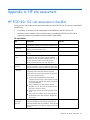
Appendix A: HP site assessment
HP POD 40c G2 site assessment checklist
During a survey of the readiness of a proposed customer site for the HP POD 40c G2, the site is inspected for
the following:
•
Accessibility of machinery for the transportation and installation of the HP POD 40c G2
•
Assessment of the suitability of the site infrastructure for installing the HP POD 40c G2 and for
supporting infrastructure preparation and serviceability requirements
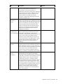
HP responsibilities
Item
Description
Sign-off
1. Engagement plan Develop an engagement plan with specific
requirements relating to the proposed installation site.
Schedule site visits on mutually acceptable dates,
2. Site visits
during normal HP business hours.
Document any test equipment used in the customer
3. Test equipment
report.
Review and discuss the proposed installation site with
4. Installation site
the customer. This initial review includes physical
review
examination of the proposed installation site and, at
the sole discretion of HP, can include physical
measurements of the area size and clearances.
Identify whether the HP POD 40c G2 installation is
5. Indoor/outdoor
indoors or outdoors as this can affect the degree and
installation
type of infrastructure required and the mounting needs.
Inspect the proposed installation site to assess
6. Site pad
compliance with the HP POD 40c G2 mounting
specifications. Ensure that the customer is fully aware
of the following requirements:
•
•
•
•
7. Materials and
construction
inspection
Proper support capabilities must exist. If the
customer intends to edge or point load on the utility
and cargo ends, there must be support in the center
to prevent deflection.
Upon installation, the POD structure must be
leveled to ≤ 0.5º, which can be checked at that
time with a surveyor’s transit.
Shimming is allowed around the perimeter of the
POD.
Place shims in increments across the length of the
HP POD 40c G2 to ensure that the HP POD 40c
G2 is level.
Visually inspect the materials and construction at the
proposed installation site to identify issues that can
impact the HP POD 40c G2 installation. Verify that the
area is adequate for truck delivery, staging, and crane
location.
Appendix A: HP site assessment 27
Item
Description
Sign-off
Inspect the proposed installation site to confirm
clearance requirements for installation and
serviceability as per the HP POD 40c G2
specifications. Necessary clearances are determined,
in part, based on the specific installation plans and
infrastructure design. Location, orientation, and
planned utilization can affect the necessary
clearances. Consider future planning for the space
around the installation site.
Evaluate the HP POD 40c G2 installation site in
9. Support
relation to the planned support infrastructure location.
infrastructure
Conduit lengths and the utility pathway design must be
location
taken into consideration in the planning stages. The
proposed support infrastructure design and the
location of required utilities are discussed with the
customer's site engineering personnel to identify
elements that can impact the HP POD 40c G2
installation site decisions.
Evaluate the proposed installation site for the HP POD
10. Support
40c G2 and the support infrastructure for access
infrastructure for
access requirements requirements. The evaluation is based on the
information provided by the customer at the time of the
site visit. In the absence of installation-specific
information, general requirements are used as the
basis for the evaluation. The delivery path is visually
examined and discussed with the customer's site
engineering personnel to identify obstacles to
installation.
11. Site engineering Conduct interviews with the customer's site
engineering personnel and site facilities personnel to
interviews
gather information related to the origin of the power
source and network services proposed for use with the
HP POD 40c G2. HP must visually inspect the
proposed power protection equipment. Means of
delivery, connections, and pathways are documented.
Based on the review of customer-provided site
12. Capacity of
documentation (such as single-line and as-built
electrical
drawings), examine equipment panels and monitoring
infrastructure
system data, as available. HP must determine whether
adequate capacity exists in the current electrical
infrastructure to be used or if additional study is
required. Determine if the level of redundancy required
as stated by the site engineering personnel can be
provided by using the existing infrastructure. This takes
into consideration the proposed installation site of the
HP POD 40c G2, the potential HP POD 40c G2
payload, and the customer stated redundancy
requirement. Components can include generators,
UPSs, and switch gear.
8. Clearances
Appendix A: HP site assessment 28
Item
Description
13. Chilled water
infrastructure
Determine the overall chilled water capacity, available
flow rates, and supply/return temperature restrictions.
Determine if there are any site specific requirements
that mandate additional chilled water equipment, such
as heat exchangers or mixing apparatus. Locate any
existing or planned supply/return headers.
Conduct interviews with the customer site engineering
personnel to determine the level of security required for
the HP POD 40c G2 and its infrastructure. The
proposed installation site is assessed for suitability in
relation to the customer requirements.
Following the HP installation site visit, analyze the data
collected and prepare a report of findings. HP must
identify potential obstacles to installation and
recommendations for any additional testing or
changes to the installation plan.
14. Security
15.
Recommendations
Sign-off
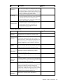
Customer responsibilities
Item
Description
Sign-off
1. Point of contact Provide HP with the name and telephone number of the
designated point of contact for the purposes of this
information
service.
2. Service listing Provide all information required under this service listing
or reasonably determined by HP to be necessary to
information
deliver the service, including but without limitation, any
documentation (internal or external) regarding prior
plans or investigations used to identify the proposed
installation site.
Provide a timely response (such as, in a time period that
3. Timely
does not adversely affect the HP scheduled performance
response
of the service) to all requests for information by HP.
Provide HP access to all subject areas and support areas,
4. Access to
subject areas and including the proposed installation site and the
mechanical or electrical infrastructure provided to
support areas
support the HP POD 40c G2.
5. Badge access Provide HP badge access or an escort for the duration of
the site visit to facilitate required access to all necessary
areas.
Customer site engineering personnel familiar with the
6. Site
proposed installation site and personnel responsible for
engineering
the maintenance and support of the existing infrastructure
personnel
must be available to answer questions.
7. Documentation Provide HP copies of all available mechanical and
electrical system design documentation, including as-built
drawings and electrical single-line drawings. As
appropriate to the specific location, provide HP with
campus maps, building drawings, floor plans, and other
relevant prints to assist in the documentation and
evaluation of the proposed installation site.
Provide HP information regarding the planned network
8. Network
infrastructure connection points and pathways.
infrastructure
information
Appendix A: HP site assessment 29
Item
Description
9. Permission for
Photographs
Grant HP permission to take photographs for report
illustration purposes.
Sign-off
Arrange site-specific project logistics at the time of
scheduling. Failure to provide necessary authorizations
can limit the effectiveness of the service and can, at the
discretion of HP, impact scheduling or result in the
postponement of the service.
11. Business visas Provide assistance in instances where a temporary
business visa is required for HP personnel to visit the site.
This assistance typically takes the form of preparing a
letter of invitation. In some cases, a formal request must
be made by the local company for which the work is
taking place.
10. Project
logistics
Appendix A: HP site assessment 30
Appendix B: Preparing for delivery
Pre-delivery tasks
Allow adequate time for planning, scheduling, obtaining permits, design approval, inspections, and so on.
Installation prerequisites
Before installing the HP POD 40c G2, verify that the following prerequisites are met:
•
All components are delivered to the facility.
•
The HP POD 40c G2 and power distribution components are in the final location.
•
Facility power, water, and drainage are at the final location.
•
Provisions for properly grounding the HP POD 40c G2 are made.
•
Required clearances exist, including overhead.
•
All trade personnel required for assembly are coordinated.
HP POD 40c G2 site readiness checklist
Before installing the HP POD 40c G2, follow all steps listed in this guide, the site plan, and the following
checklists.
Architectural/environmental considerations
Item
Description
1
Verify that the site location supplies sufficient locations for
support. Ensure that upon installation the POD can be leveled to
≤ 0.5º. If edge or point loading is used, ensure a center
support can be accomplished using shims and so on, to ensure
that the POD can be properly leveled. Shimming is allowed
around the perimeter in increments. A surveyor’s transit should
be used upon installation to check the POD leveling
requirements.
Verify that the pad can support the total weight of the HP POD
40c G2 solution by verifying that load calculations have been
performed by your engineering team.
Verify that the site has provisions for grounding.
2
3
4
5
6
Sign-off
Verify the HP POD 40c G2 is not in the direct path of any
external heat loads, such as generators.
Determine the average local temperatures and ensure that
adequate environmental protection is provided, such as cold
weather protection, if required.
Verify that the site altitude is less than 3,048 m (10,000 ft).
Appendix B: Preparing for delivery
31
Item
Description
7
When installing on an elevated surface, verify that the
maximum height requirements for the circuit breaker actuator
meet the local and national requirements. Verify that proper
landings and the catwalk are planned for electrical cabinet
access.
Verify the planning for required egress routes for all HP POD
40c G2 personnel doors, cargo doors, and service area doors,
including landings, the catwalk, and stairs.
Verify that the local AHJ is contacted, all applicable codes and
site-specific location guidelines are reviewed, and all required
permits are obtained.
Verify that the site location has clearances for the HP POD 40c
G2 installation, including any permanent structures, such as
fences, walls, vestibules, and buildings.
Verify that all utilities, overhead and underground, are
identified to maintain required clearance.
Verify that there is adequate clearance around the HP POD 40c
G2 for door operation, installation, and maintenance
equipment.
Verify that the site location and site pads are marked for any
transformer, external switchboard, generators, and
powerhouses.
Verify that the site has provisions for proper grounding and that
the site location includes a grounding electrode system.
Verify that the site location has adequate lighting for the HP
POD 40c G2 installation.
Verify that a truck and equipment staging areas are identified.
8
9
10
11
12
13
14
15
16
17
18
19
20
21
22
23
24
25
26
27
Sign-off
Verify the location for the fuel tanks for generators,
powerhouses, and other equipment, if applicable.
Verify the locations for cranes off-loading and operation during
HP POD 40c G2 installation.
Verify site access and clearances for equipment, including the
crane and forklifts. A clear path to the site must be maintained
with clearance for all gates, headers, utility lines, and so on.
Verify that the locations for storage and trash disposal are
identified.
Verify that the safety equipment is planned for and in place in
accordance with the customer’s site safety program.
Verify the site interfaces and locations to connect the fire alarm,
security system, and communication system to the HP POD 40c
G2. This ensures that the POD can be properly connected to the
site BMS.
Verify that proper disposal methods are used for existing or
potentially contaminated and/or hazardous materials.
Verify the availability of security systems or equipment,
including site fences, required after construction.
Verify the availability of temporary facilities associated with the
relocation of existing services and operations.
Verify that all work relating to soil testing, removal, and that site
remediation is complete.
Verify that a temporary or permanent load bank is available, if
applicable.
Appendix B: Preparing for delivery
32
Item
Description
28
Verify the location of the EPO system external to the
powerhouses, if applicable.
Verify the location of the remote electronic monitoring system.
29
30
Sign-off
Verify that tie-downs and other AHJ-required facilities for the HP
POD 40c G2 and power containers are complete at least one
week prior to arrival of HP-provided equipment.
General water supply
Item
Description
1
Verify that the site drainage is complete, and the HP POD 40c
G2 is not in a drainage path or flood prone area. HP
recommends placing the HP POD 40c G2 on a raised site pad
to prevent water from entering the HP POD 40c G2.
Verify that the humidification water quality meets or exceeds
these standards, which are essentially drinking water
standards.
Verify the humidification water supply isolation valve is
installed for each POD.
2
3
Sign-off
Chilled water system
Item
Description
1
Verify the chilled water supply and return headers are
accessible, in the appropriate location, and 100 cm (4 in) in
diameter.
Verify that the chilled water supply temperature meets the
minimum POD chilled water supply temperature of 10°C
(50°F).
Verify that a sufficient chilled water flow rate is available.
2
3
4
Sign-off
If necessary, verify that the customer-required chilled water
return temperatures can be attained.
Power requirements
Item
Description
1
Verify that the short circuit analysis, arc flash, and circuit
breaker coordination studies are complete. Verify power work
is completed according to the approved conduit routing
drawings that show the exact routes, plan view, sections, and
elevations.
Verify that temporary site power for installation and
construction is planned and available, if applicable.
Verify that adequate site power exists per the HP POD 40c G2
requirements.
2
3
Sign-off
General
Item
Description
1
Verify the utility connection to the HP POD 40c G2 and any
required metering equipment.
Verify the third-party commissioning services that might be
required by the owner.
2
Sign-off
Appendix B: Preparing for delivery
33
Item
Description
3
Verify that the HP Project Team coordinates with other site
construction activities.
Sign-off
Appendix B: Preparing for delivery
34
Appendix C: Regulatory compliance notices
HP POD 40c G2 regulatory compliance
The HP POD 40c G2 complies with the following regulatory standards.
Standard
Certification level
Standard title
UL 60950
ETL "Listed"
•
•
UL 60950—Standard for Safety Information Technology
Equipment, Part 1: General Requirements, Issue: 2007/03/27,
Edition: 2
UL 60950—Standard for Safety Information Technology
Equipment, Part 22: Equipment to be Installed Outdoors, Issue:
2007/04/23, Edition: 1
NFPA 70
ETL "Classified"
NFPA 70—National Electric Code, 2008 Edition, © 2008 National
Fire Protection Association
NFPA 72
Designed to Comply
With
National Fire Alarm code, 2007 Edition, © 2006 National Fire
Protection Association
NFPA 2001 Designed to Comply
With
IBC 2009
Designed to Comply
With
NFPA 2001, Standard on Clean Agent Fire Extinguishing Systems,
2008 Edition, © 2008 National Fire Protection Association
2009 International Building Code, © 2010 International Code
Council, Inc.
Regulatory compliance identification numbers
For the purpose of regulatory compliance certifications and identification, this product has been assigned a
unique regulatory model number. The regulatory model number can be found on the product nameplate
label, along with all required approval markings and information. When requesting compliance information
for this product, always refer to this regulatory model number. The regulatory model number is not the
marketing name or model number of the product.
Federal Communications Commission notice
This equipment has been tested and found to comply with the limits for a Class A digital device, pursuant to
Part 15 of the FCC Rules. These limits are designed to provide reasonable protection against harmful
interference when the equipment is operated in a commercial environment. This equipment generates, uses,
and can radiate radio frequency energy and, if not installed and used in accordance with the instructions,
may cause harmful interference to radio communications. Operation of this equipment in a residential area
is likely to cause harmful interference, in which case the user will be required to correct the interference at
personal expense.
Modifications
The FCC requires the user to be notified that any changes or modifications made to this device that are not
expressly approved by Hewlett-Packard Company may void the user’s authority to operate the equipment.
Appendix C: Regulatory compliance notices
35
Cables
Connections to this device must be made with shielded cables with metallic RFI/EMI connector hoods in
order to maintain compliance with FCC Rules and Regulations.
Canadian notice (Avis Canadien)
This Class A digital apparatus meets all requirements of the Canadian Interference-Causing Equipment
Regulations.
Cet appareil numérique de la classe A respecte toutes les exigences du Règlement sur le matériel brouilleur
du Canada.
Appendix C: Regulatory compliance notices
36
Glossary
AHJ
authority having jurisdiction
APJ
Asia Pacific Japan
BMS
building management system
door
A hinged portion of an enclosure that covers an opening.
DX
direct expansion
ECS
environmental control system
EMEA
Europe, Middle East, and Africa
EPO
emergency power off
equipment
A general term, including fittings, devices, appliances, luminaires, apparatus, machinery, and the like used
as a part of, or in connection with, a modular data center. (Source: NEC.)
IEC
International Electrotechnical Commission
ISO
International Organization for Standardization
Glossary
37
labeled
Equipment or materials to which has been attached a label, symbol, or other identifying mark of an
organization that is acceptable to the authority having jurisdiction and concerned with product evaluation,
that maintains periodic inspection of production of labeled equipment or materials, and by whose labeling
the manufacturer indicates compliance with appropriate standards or performance in a specified manner.
listed
Equipment, materials, or services included in a list published by an organization that is acceptable to the
authority having jurisdiction and concerned with evaluation of products or services, that maintains periodic
inspection of production of listed equipment or materials or periodic evaluation of services, and whose listing
states that either the equipment, material, or service meets appropriate designated standards potential of not
more than 42.4 V (DC or peak) supplied by a primary battery or by an isolated secondary circuit, and where
the current capacity is limited by an overcurrent device, such as a fuse, or by the inherent capacity of the
secondary transformer or power supply, or a combination of a secondary winding and an impedance. A
circuit derived from a line-voltage circuit by connecting a resistance in series with the supply circuit to limit the
voltage and current is not identified as a low-voltage limited energy circuit. or has been tested and found
suitable for a specified purpose.
The means for identifying listed equipment might vary for each organization concerned with product
evaluation, some of which do not recognize equipment as listed unless it is also labeled. Use of the system
employed by the listing organization allows the authority having jurisdiction to identify a listed product.
NA
North American
overcurrent protection
A device designed to open a circuit when the current through it exceeds a predetermined value. The ampere
rating of the device is selected for a circuit to terminate a condition where the current exceeds the rating of
conductors and equipment due to overloads, short circuits and faults to ground.
structure
Enclosure of sufficient size to enable entry of personnel.
UL
Underwriters Laboratory
UPS
uninterruptible power system
VESDA
very early smoke detection apparatus
Glossary
38
Documentation feedback
HP is committed to providing documentation that meets your needs. To help us improve the documentation,
send any errors, suggestions, or comments to Documentation Feedback (mailto:[email protected]).
Include the document title and part number, version number, or the URL when submitting your feedback.
Documentation feedback
39
Index
A
G
about this guide 5
areas prone to lightning or power surges 22
assembly 31
assembly area 24
grounding requirements 11
C
cables, FCC compliance 36
Canadian notices 36
capacity limitations 7
central facility infrastructure connections 17
clearance area 8, 10
cold weather considerations 22
connection portals 17
connections, additional 17
connections, facility 17
H
HP site preparation drawing package 23
humidifier 20
I
installation 24
installation equipment 24
IT cable portals 17
L
lifting layout and requirements 24
lightning protection 22
D
M
delivery considerations 31
dimensions 8
materials, piping 15
mechanical cooling capacity 7
modifications, FCC notice 35
E
N
electrical power capacity 7
electrical system 15
environmental considerations 22
environmental control system (ECS) 17
environmental risks 22
equipment, installation 24
expansion 11
other objects 25
overview 5
F
P
facility connections 17
FCC (Federal Communications Commission)
notice 35
Federal Communications Commission (FCC)
notice 35
fire and safety 20
fire suppression 6
future expansions 11
permit requirements 23
piping materials 15
portals, connection 17
power infrastructure installation 15
power surges 22
pre-delivery 31
preparing for assembly 31
project coordination 23
proximity to utilities and drains 12
network connections 17
O
Index
40
R
regulatory compliance identification numbers 35
regulatory compliance, HP POD 40c G2 35
S
safety information 6, 10
security 6, 20
seismic activity 22
site assessment 6, 23, 27
site assessment checklist 27
site pad 8
site planning considerations 24
site preparation 6
site preparation checklist 31
site requirements 8
storage locations 25
supported facility connections 17
system capacity 7
T
transformer and switchboard 16
U
utilities 12
V
vestibule specifications 25
W
water supply 12, 13
weight 8
Z
zoning and permit requirements 23
Index
41