1
40 LCGC NORTH AMERICA VOLUME 23 NUMBER 1 JA N UA RY 2005
www.chromatographyonline.com
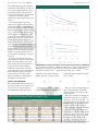
615 s, the inner diameter would have to
fall within 66 mm or about 62.4% of the
nominal 250-mm inner diameter for the
longest retained peak shown here; within
610 mm for the middle peak; and within
620 mm for the earliest eluted peak.
As peak retention increases, the variability in inner diameter required to keep peaks
within a defined range decreases rapidly.
Howe ve r, with isothermal elution, the
widths of the peaks increase with longer
retention, and the effect of the variability
becomes less significant. This is not the case
for temperature - p rogrammed elution, but
this topic lies outside of the discussion
being presented here .
Thus, it appears that for columns of the
same type used for the same isothermal
analysis, if the inner diameters from one
column to the next lie within less than
62% of the nominal diameter, then peaks
will be eluted within a fairly tight window.
Remember, though, that other variables are
also at play here. Temperature and pressure
variability will add more uncertainty to the
retention times.
Column Length
Variations in column length also affect
retention times. Di f f e rences between column lengths on the order of 1 m or more
a re not uncommon within a population of
initially equal-size columns that have been
in use for some time. Re m oval of a small
p o rtion of a column is part of good laborat o ry practices that call for the use of new
inlet and detector ferrules with each installation. Additional lengths can be remove d
from the column entrance as part of column reconditioning in order to re m ove
n o n volatile sample residues that have accumulated at the beginnings of columns.
The effects of varying column lengths
depend upon how the analyst sets up the
columns. One approach would be to
choose the same pre s s u re drop for all
columns of a particular type. In this case,
retention times will va ry with the square of
the column length, as shown in equation 3,
which was obtained by combining equations 1, 2, and 3 from the first installment
of this column series (1):
[3]
This is not a desirable situation. The
peak with partition coefficient K 5 522 at
100 °C (n-dodecane), which is eluted in
227 s on a 25-m column with a 15.0-psig
pressure dro p, would shift to 210 s on a
24-m column with the same pre s s u re dro p.
The effect on later-eluted peaks would be
e ven larger.
If, on the other hand, the carrier-gas linear velocity we re set the same for the 24-m
column as the 25-m column, by adjusting
the inlet pre s s u re dow n w a rd slightly to 14.4
psig for the shorter column, then the same
peak would shift by about half as much, to
a round 218 s. Keeping the retention time
the same for both column lengths would
require a further decrease in the shorter column’s pre s s u re drop to around 13.8 psig.
This pressure corresponds to an ave r a g e
carrier-gas linear velocity that is exactly the
ratio of the two columns’ lengths times the
original velocity. In this case, that’s
24.0/25.0 3 34.0 5 32.64 cm/s. The other
peaks follow suit in this case and have the
same retention times on the shorter column
under these lowe red inlet pre s s u re conditions as they do on the longer column at
15.0 psig.
Setting up by linear velocity: In practice, it’s fairly easy to set up a column in
this manner. First, measure the approximate
length of the column by counting the turns
(include any fractional first or last turn)
and multiplying by the average length of a
single turn, as in equation 4:
L ≈ tc • p dh
length, for which the method conditions
we re developed. Third, multiply by the
d e s i red average carrier gas linear velocity for
the method to obtain the linear velocity
goal for the specific column being installed,
as shown in equation 5:
[5]
Finally, as part of verifying the setup,
establish the operating or initial column
t e m p e r a t u re and then adjust the inlet pre ss u re as required to produce the calculated
velocity.
For GC systems with electronic pre s s u re
c o n t rol (EPC), the EPC system will calculate and set the correct pressure for the
d e s i red velocity if the measured column
length is entered first. Howe ve r, slight va r iations in the column diameter from the
nominal diameter can produce a slight
e r ror in this step. The operator can approx imate the apparent column diameter at this
point by comparing the measured carrier
gas linear velocity to the desired value as
e n t e red into the EPC system. Be c a u s e ,
a c c o rding to equation 2, the ratio of the
velocities is equal to the square of the ratio
of the diameters, a corrected diameter can
be calculated in this manner:
[6]
[4]
w h e re tc is the turns count and dh is the
nominal column helical coil diameter. Use
a value of dh that’s close to the appare n t
a verage value for the coils of the column.
Next, calculate the ratio of the length of
the column at hand to the nominal column
For the example given above, if the
d e s i red velocity was 32.64 cm/s for the 24
m 3 250 mm column, but the observe d
velocity was 34.9 cm/s, then the corrected
column inner diameter would be:
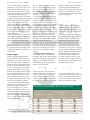
Table II: Retention times (in seconds) for three peaks across a narrow range of column
inner diameters, o p e rated isothermally at 100 °C. For conditions, see Fig. 1.
Peak Retention Time (s)
Inner Diameter (mm)
240
242
244
246
248
250
252
254
256
258
260
n-Dodecane
n-Undecane
n-Nonane
K100°C 5 522.1
K100°C 5 270.2
K 100°C 5 70.99
253.7
248.1
242.7
237.4
232.3
227.4
222.6
217.9
213.4
209.0
204.8
169.8
166.3
162.9
159.5
156.3
153.2
150.1
147.2
144.3
141.5
138.8
103.5
101.6
99.8
98.0
96.2
94.5
92.9
91.3
89.7
88.1
86.7