1
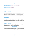
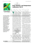
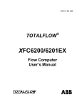
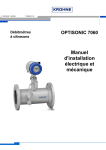
SOFTWARE MANUAL
FLOWSIC600
Ultrasonic Gas Flow Meter
II+
Analyzers and Process Inst rumentation
FLOWSIC600
Software Manual
Ultrasonic Gas Flow Meter
Content
About this document...........................................................................................................5
1 Safety instructions...............................................................................................................6
2 General ....................................................................................................................................9
2.1
2.2
2.3
2.4
2.5
8 010 543 / 03-2007
Installation..................................................................................................................................9
2.1.1
System requirements ......................................................................................................................... 9
2.1.2
Compatibility............................................................................................................................................ 9
2.1.3
Communication through the RS232 port of the FLOWSIC600 .......................................... 9
2.1.4
USB communication ......................................................................................................................... 11
2.1.5
Installing the software driver for the interface adapter ...................................................... 12
2.1.6
MEPAFLOW600 software installation ........................................................................................ 13
Establishing a connection.................................................................................................. 14
2.2.1
Logging on ........................................................................................................................................... 14
2.2.2
Establishing a connection to the FLOWSIC600 .................................................................... 14
2.2.3
Support in case of communication problems ........................................................................ 15
Navigating the program ...................................................................................................... 17
2.3.1
Tabs ....................................................................................................................................................... 17
2.3.2
Menu bar .............................................................................................................................................. 18
2.3.3
Tool bar ................................................................................................................................................. 19
2.3.4
Status bar ............................................................................................................................................ 19
Basic settings ........................................................................................................................ 20
2.4.1
Pre-requisites ...................................................................................................................................... 20
2.4.2
Switching to the configuration mode ......................................................................................... 20
2.4.3
Configuration ....................................................................................................................................... 20
Data saving concept ............................................................................................................ 24
2.5.1
General ................................................................................................................................................. 24
2.5.2
Session file – session concept .................................................................................................... 24
2.5.3
Program language file ...................................................................................................................... 34
2.5.4
Program initialisation file ................................................................................................................. 34
2.5.5
Device configuration file ................................................................................................................. 34
2.5.6
ASCII export files ............................................................................................................................... 34
2.5.7
EEPROM memory image ................................................................................................................ 34
2.5.8
FLASH memory image .................................................................................................................... 34
© SICK MAIHAK GmbH · Germany · All rights reserved
3
FLOWSIC600
Software Manual
Ultrasonic Gas Flow Meter
3 Using the program.............................................................................................................37
3.1
3.2
4
Tabs ........................................................................................................................................... 37
3.1.1
“Measured values” tab ................................................................................................................... 37
3.1.2
“Device parameters” tab ............................................................................................................... 38
3.1.3
“Adjustment” tab ............................................................................................................................... 41
3.1.4
“Device diagnosis” tab .................................................................................................................... 45
3.1.5
“Path diagnosis” tab ......................................................................................................................... 46
3.1.6
“Device logbook” tab ....................................................................................................................... 49
3.1.7
“Log/ trend” tab ................................................................................................................................. 50
3.1.8
Programming the flash memory .................................................................................................. 51
Data recorder ......................................................................................................................... 52
3.2.1
Data logging ........................................................................................................................................ 52
3.2.2
Replaying tab contents ................................................................................................................... 54
© SICK MAIHAK GmbH · Germany · All rights reserved
8 010 543 / 03-2007
About this document
Software Manual
FLOWSIC600
Ultrasonic Gas Flow Meter
About this document
This Software Manual describes the control and configuration program MEPAFLOW600 for
the Ultrasonic Gas Flow Meter FLOWSIC600. It contains general information about system
configuration and diagnosis options. Additional information and is available from your SICK |
MAIHAK representative.
Information on the operation of the FLOWSIC600 can be found in the Operating Manual of
the measuring system.
The FLOWSIC600 documentation further includes (for specially trained staff only):
• Service Manual
• Extraction Tool Operating Manual
Symbols used in this document
Note
To provide information about special features of the equipment and further
recommendations.
Important
To indicate potential dangers to the equipment and possible functional impairment.
IMPORTANT
Warning
WARNING
To indicate potential dangers to the operating staff, in particular due to electrical equipment
and improper use of the equipment. Always observe such warnings, as they aim to protect
you from serious injuries.
Read Warning notes carefully and follow them strictly!
Note
8 010 543 / 03-2007
Always read this manual carefully before carrying out any work on the equipment. Always
comply with any safety instructions and warnings.
© SICK MAIHAK GmbH · Germany · All rights reserved
5
FLOWSIC600
Safety instructions
Software Manual
Ultrasonic Gas Flow Meter
1
Safety instructions
Intended use
The control and configuration software MEPAFLOW600 is used for configuration, data
display and output as well as diagnosis of the Ultrasonic Gas Flow Meter FLOWSIC600.
Authorised staff
Persons responsible for safety issues shall ensure the following points:
• Any work on the measuring system shall only be carried out by qualified persons and
must be checked by responsible skilled persons.
Due to their professional training, knowledge and vocational experience, as well as their
knowledge of the relevant standards, regulations, health and safety regulations and
equipment conditions, qualified persons shall be assigned by the person responsible for
personal and plant safety to carry out such work. Qualified persons must be able to
identify possible dangers and to take preventive action in due time.
Skilled persons are defined in DIN VDE 0105 and IEC 364, or comparable standards.
• In hazardous areas, wiring and installation shall only be carried out by staff trained
according to EN 60079-14 and according to national regulations.
General safety instructions and protective measures
Always comply with the safety instructions specified where necessary and the instructions
given in the FLOWSIC600 Operating Manual when using the software.
6
© SICK MAIHAK GmbH · Germany · All rights reserved
8 010 543 / 03-2007
FLOWSIC600
Ultrasonic Gas Flow Meter
General
Installation
Establishing a connection
Navigating the program
Basic settings
Data saving concept
General
Software Manual
FLOWSIC600
Ultrasonic Gas Flow Meter
2
General
2.1 Installation
2.1.1
System requirements
The software requires a PC system with Windows 95/98, Me, 2000 or NT, and:
• 32 MB RAM
• 266 MHz Pentium processor
• Free serial port
• SVGA (800x600) compatible graphics card
In addition, an RS485 / RS232 converter capable of handling baud rates of up to
57,600 kbit and automatic signal direction switch is required for direct connection of the
FLOWSIC600 with the serial port of the PC.
Note
The MEPAFLOW600 software does not support the modem signal direction control signals
of the serial interface (RTS, CTS)!
2.1.2
Compatibility
The MEPAFLOW version 3.x software can not be used for older Firmware/ Hardware
versions. The following MEPA/ Firmware version are compatible:
– Version 2.x.x for devices with Firmware version 2.x.x
– Version 3.x.x for devices with Firmware version 3.x.x
2.1.3
Communication through the RS232 port of the FLOWSIC600
The serial port is wired to correspond with the RS485 standard. External devices are
connected through a shielded twisted pair cable. The connections are marked “+” and “-”
and are connected “1:1”, i.e. “+” on the FLOWSIC600 is connected with “+” on the
converter, “-” on the FLOWSIC600 with “-” on the converter.
Other commonly used labels for these terminals are:
Terminal
8 010 543 / 03-2007
Other commonly used designation
+
A
Y
Data +
–
B
G
Data –
© SICK MAIHAK GmbH · Germany · All rights reserved
9
General
FLOWSIC600
Software Manual
Ultrasonic Gas Flow Meter
Terminals on the SPU
Terminal 33: RS485 +
Terminal 34: RS485 –
9-pin
COM port
Terminals
1:1
Connection
cable
Fig. 2.1: Wiring example of the ADAM 4520 RS485 / RS232 converter
Note
Make sure the Tx signal transmitted by the PC is connected with the reception channel Rx
at the converter, and the Tx signal transmitted by the converter is connected with the
reception channel Rx at the PC. The signal lines must always be crossed with any RS232
connections. If this is not realised inside the converter, the user must ensure that the lines
are crossed externally. You may use a so-called ’Null Modem Kabel’ for this purpose.
Converter
2
txd
rxd
2
3
rxd
txd
3
5
gnd
gnd
5
Fig. 2.2:
Note
10
PC
9-pin
COM port
Typical RS232 wiring between interface converter (ADAM 4520 with lines crossed
internally) and PC
A MEPA Interface Set, consisting of interface converter, interface cable RS232 and power
supply unit, is available on request under the order number 7041773.
© SICK MAIHAK GmbH · Germany · All rights reserved
8 010 543 / 03-2007
General
Software Manual
FLOWSIC600
Ultrasonic Gas Flow Meter
2.1.4
USB communication
If the PC or laptop used to control the FLOWSIC600 does not have an RS232 serial port,
you may use the USB.
The interface adapter is designed to allow both direct access to the flash memory and the
use of the serial interface using the MODBUS protocol.
LED will be green if the PC uploads
data to the FLOWSIC600
LED will be orange if the PC receives
data from the FLOWSIC600
USB-port for direct PC
connection
33 +
34 -
10-pole connector for
connection to the
electronics block
Fig. 2.3: Service interface adapter USB Rev2 (order no. 2040718)
Achtung
For connection with increased safety chose the corresponding connection adapter (e.g.
STAHL 9185).
IMPORTANT
8 010 543 / 03-2007
© SICK MAIHAK GmbH · Germany · All rights reserved
11
General
FLOWSIC600
Software Manual
Ultrasonic Gas Flow Meter
2.1.5
Installing the software driver for the interface adapter
Note
The interface adapter can only be used on PCs which run under the operating systems
Windows 98, Windows 2000, Windows XP.
– Plug in the USB connector at the PC.
– The operating system will signal to have found new hardware. Insert the FLOWSIC600
CD ROM which is included in the delivery and follow the installation assistant (see Fig.
2.4).
– After completion of the installation, a second installation will be performed for software
reasons. This second installation must not be interrupted -- please follow the assistant
again.
Fig. 2.4: Installing the driver
12
© SICK MAIHAK GmbH · Germany · All rights reserved
8 010 543 / 03-2007
General
Software Manual
FLOWSIC600
Ultrasonic Gas Flow Meter
2.1.6
Use the Windows Exploerer,
Win Commander or similar
administration program, or
select the “Run…”
command from the “Start”
menu.
MEPAFLOW600 software installation
The software must be installed on the PC before it can operate. For this insert the productCD, which is attached to the FLOWSIC600 when it is delivered, into the appropriate drive.
Folllow the Auto-Start-Menue or start the file ,FLOWSIC600_R_CD’. After that the user is
guided automatically.
Fig. 2.5: Files on the Product-CD
8 010 543 / 03-2007
© SICK MAIHAK GmbH · Germany · All rights reserved
13
General
FLOWSIC600
Software Manual
Ultrasonic Gas Flow Meter
2.2 Establishing a connection
You can run the program after successful installation by selecting the MEPAFLOW600 entry
in the program group created during installation, or by double-clicking on the desktop icon.
Fig. 2.6: Starting the program from the “Start” menu or with the desktop icon
2.2.1
Logging on
When starting the program the “Connect to” dialog box will appear on the screen.
Fig. 2.7: Connect to dialog box
Select the desired access level in the “Password level” field. The following table shows the
differences between the individual access levels.
User
You must enter a password
for access to the ‘authorised
operator’ and ‘service’ levels
(passwords for access levels
1 and 2 can be found in the
device documentation).
2.2.2
Access level
Possible activities
Operator
0
Important information is provided for display and
recording, parameters cannot be modified.
Authorised operator
1
For trained staff. I/O parameters can be modified in
addition to level 0.
Service (field)
2
Any diagnosis information available. Parameters can be
modified, but no access to signal models. Software
update possible.
Service (manufacturer)
3
No restrictions
Establishing a connection to the FLOWSIC600
Select an available port on the PC from the dropdown list in the “Connection” field (see
“Connect to” dialog box, Fig. 2.7) to make a serial communication line to the FLOWSIC600.
14
© SICK MAIHAK GmbH · Germany · All rights reserved
8 010 543 / 03-2007
General
Software Manual
FLOWSIC600
Ultrasonic Gas Flow Meter
If you select “Offline”, the program will be run without establishing an online communication
line to the FLOWSIC600.
The MODBUS protocol implemented in the device generally accepts bus wiring, so that you
must assign the FLOWSIC600 a device address (see Fig. 2.7). All FLOWSIC600 are
delivered with the device address ‘1’.
The program will automatically try to communicate with a FLOWSIC600 on the specified
device address through the serial port. It will start communication at a pre-set baud rate of
9600 Baud. If a connection can be established, the program will test higher baud rates one
after another. If communication attempts fail at any of the tested baud rates, the program
will suggest to search for alternative device addresses.
Fig. 2.8: Warning
Notes
• The device firmware is programmed to allow communication with any FLOWSIC600 on
the general address ‘0’ in addition to the address set on the individual device.
• This option shall only be used if there is just one direct connection between a
FLOWSIC600 and the PC. The reaction of further devices connected on the bus on a
broadcast command may affect the results of this attempt.
see Sections 2.3.1 and
3.1.1
2.2.3
The “Measured values” tab will be opened on successful connection.
Support in case of communication problems
The table below shall help you in case of communication errors between the PC and the
FLOWSIC600.
Problem
Possible reason
Remedy
No communication between
MEPAFLOW600 and
FLOWSIC600
FLOWSIC600 power supply defective
• Check voltage at the terminals 1+, 2 in the terminal box
of the FLOWSIC600 using a multimeter (reading must
be between 12 and 30 V).
• Replace the power supply unit if necessary
Voltage reversal at the FLOWSIC600
power supply
• Make sure the power supply unit of the FLOWSIC600
Converter power supply defective
(only applies to converters with external
power supply)
• Check voltage at the converter using a multimeter
• Compare with the manufacturer specifications
• Replace the power supply unit if necessary
Wrong RS485 wiring
• Make sure the signal conductor (+) of the converter is
is connected in accordance with the marking inside the
terminal box.
connected to terminal 33
• Make sure the signal conductor (-) of the converter is
connected to terminal 34
8 010 543 / 03-2007
© SICK MAIHAK GmbH · Germany · All rights reserved
15
FLOWSIC600
General
Software Manual
Ultrasonic Gas Flow Meter
Problem
Possible reason
Remedy
No communication between
MEPAFLOW600 and
FLOWSIC600
Wrong RS232 wiring
• Make sure wining is in accordance with Section – and
2.1.4
• Make sure the signal reception conductor is connected
with the signal transmission conductor and vice versa
(txd and rxd crossed, see also Section –)
Wrong COM port at the PC
• Select a different COM port in the “Connect to“ dialog
box
Device wrongly addressed
• Make sure the device address selected in the
“Connect to“ dialog box corresponds with the device
address of the FLOWSIC600
• If connection has failed, try connecting to device
address ‘0’
RS232 connection cable defective
• Check cable continuity
• Find out whether or not rxd and txd conductors must
be crossed in the cable (see Section –)
RS485 connection cable defective
• Check cable continuity
Converter does not support the automatic • Use a different interface converter, such as ADAM
simulation of the modem control signals
4520 (see Sections – and 2.1.4)
RTS and CTS
Wrong baud rate selection at the
converter
• Make sure FLOWSIC600 and converter operate at the
same baud rate
• Use a converter with automatic baud rate detection
FLOWSIC600 service port defective
• Contact the manufacturer
RS232 cable too long
• Make sure the cable is no longer than 5 m
RS485 cable too long
• Make sure the cable is no longer than 1,000 m
Power supply of the laptop port
insufficient for the converter
(only applies to laptop users in
conjunction with converters supplied
through the serial port)
• Use a converter with external power supply
• Install MEPAFLOW600 on a desktop PC and try again
No COM port available in the
“Connect to“ dialog box
All COM ports of the PC or laptop are
occupied by other devices (modems,
IRDA interfaces etc.)
• Use the Device Manager of the Windows Control Panel
Slow signal transmission and
screen refreshing
PC does not meet the hardware
requirements
• Upgrade your PC or replace it by a suitable model
Electromagnetic interference in the
communication line
• Apply additional shielding measures
• Separate the signal cable from power cables
No display of measured values in MEPAFLOW600 does not support the
the MEPAFLOW600
current device software
to establish a connection
to release a COM port
• Contact the manufacturer
• Either use an earlier MEPAFLOW version or update the
FLOWSIC600 firmware
16
© SICK MAIHAK GmbH · Germany · All rights reserved
8 010 543 / 03-2007
General
Software Manual
FLOWSIC600
Ultrasonic Gas Flow Meter
2.3 Navigating the program
The MEPAFLOW600 control program was developed as an application software based on
Microsoft Windows• . The control elements used, i.e. buttons, menu bars, dialog boxes, are
designed to correspond with generally used Windows elements.
The program interface is generally divided into five parts: menu bar, tool bar (icons), tabs,
dialog area and status bar.
Menu bar
Tool bar
Tabs
Dialog area
Status bar
Fig. 2.9: Program interface on the “Service” password level
2.3.1
Detailed description see
Section 3.1.
Tabs
Availability and content of the tabs depend on the selected password level.
Tab
Password level Content
Measured
values
Operator,
Authorised
operator
Display of currently measured values of flow rate, flow velocity, sound velocity, indication of system
status, display of forward and reverse volume counters as well as forward and reverse error volume
counters
Service
Additionally, display of current measured values of flow velocity, sound velocity, error rate, gain and
signal-to-noise ratio of the individual paths
Operator
Display of parameters for calibration, frequency output, digital outputs, LCD, warning/ limit, analog
output, replacement values, path failure compensation
Authorised
operator
Display and input of parameters for calibration, frequency output, digital outputs, LCD, warning/ limit,
analog output, replacement values, path failure compensation
Service
Display of device identification parameters, display and input of all parameters for meter set-up,
process parameters, meter body, limits, profile correction, calibration, pulse and analog outputs, path
values
Device
parameters
8 010 543 / 03-2007
© SICK MAIHAK GmbH · Germany · All rights reserved
17
General
FLOWSIC600
Software Manual
Ultrasonic Gas Flow Meter
Tab
Password level Content
Adjustment
Operator,
Authorised
operator
Display od data that are used for adjustment/correction of the device
Service
Display of and access tom the adjust factors
Device
diagnosis
Operator,
Authorised
operator,
Service
Display of operational voltage and device identification information, display and test option for pulse
and analog outputs
Path diagnosis
Service
Display of path status, received signal images, measured values, path parameters
Device logbook Operator,
Authorised
operator,
Service
Display of the logbook content, option to acknowledge events
Log/ trend
Operator,
Authorised
operator,
Service
Dialog for collecting measured values, menu to select measured values for logging
Flash tool
Service
Firmware programming tool
2.3.2
Menu bar
Menu
Item
Description
File
New session
Opens a new session file (“DEFAULT.∼SF”)
Open session
Opens an existing session file
Save session
Saves the current session file
Save session as…
Saves the current session under a new name
Diagnosis session
Starts a diagnosis session
Session history
Opens the “Session history” dialog box and displays scanned session contents
Upload configuration
Starts transmission of a configuration to the FLOWSIC600
Printer selection
Opens the printer selection menu
Exit
Terminates the program after a confirmation dialog
Connection
Connection
Opens the “Connect to” dialog box (see Section 2.2.2)
Operational mode
• Configuration
• Measurement
Changes the FLOWSIC600 operational mode
Monitors
System status
Indicates the current system status
% Errors
Displays the error rates in all paths
SNR
Displays the signal-to-noise ratio in all paths
AGC levels
Displays the gain in all paths
Velocity of sound
Displays the velocity of sound in all paths
Relation of velocity of sound Relative variation of the sound velocity among the individual paths
Options
Help
18
Velocity of gas
Displays the velocity of gas in all paths
Trend set-up
Opens a dialog box to change the trend representation on the “Log/ trend” tab
(colours, time slot - X axis)
Colour adjustment
Opens a dialog box to select a global colour pattern
Language
Opens a dialog box to select the interface language
Diagnosis set-up
Opens a dialog box to select the time slot for data recording in a diagnosis
session, distinguished into signal and value recording
Version
MEPAFLOW600 program version
Help F1
Online help
© SICK MAIHAK GmbH · Germany · All rights reserved
8 010 543 / 03-2007
General
Software Manual
FLOWSIC600
Ultrasonic Gas Flow Meter
2.3.3
Tool bar
The tool bar contains major functions which can be activated quickly and simply.
Open a new session
Open an existing session
Save current session
Create a diagnosis session
Upload an external configuration file
History information of current
session and editing
Connect to device or change to offline mode
Switch device to configuration mode
Switch device to measurement mode
Open logged data
Find record…
Stop logging
Start logging
Play log
Pause
Go to first record
Go to previous record (hold mouse button down to scroll)
Go to next record (hold mouse button down to scroll)
Go to last record
Enable signal sound
Fig. 2.10: Tool bar and description of icons
2.3.4
Status bar
The status bar contains information about the following device statuses:
• Progress bar for time-consuming functions
• Indication of the current operational mode
• Indication of the current password level
• Error rate of the running data communication between device and PC
• Status indicators for data transmission and reception through the data interface
8 010 543 / 03-2007
© SICK MAIHAK GmbH · Germany · All rights reserved
19
General
FLOWSIC600
Software Manual
Ultrasonic Gas Flow Meter
2.4 Basic settings
2.4.1
Pre-requisites
Before you can use the FLOWSIC600, it is necessary to adjust the output channels of the
measuring system to match your requirements. This requires the following condition:
• The FLOWSIC600 is completely mounted and wired.
• The MEPAFLOW600 program is installed on a PC or laptop.
Proceed as follows:
‡ Connect the RS485 / RS232 interface converter to the terminals 33+ and 34- in the
terminal box of the signal processing unit.
‡ Connect the COM port of the PC or laptop with the interface converter.
‡ Start the PC and run MEPAFLOW600.
‡ Establish a connection on the password level “Authorised operator”.
2.4.2
Switching to the configuration mode
If you are successfully connected, the control program will show all measured values and
parameters in accordance with the selected password level. Switch the device to the
configuration mode to be able to perform any changes of the parameters: Click on the
“Switch device to configuration mode” button in the tool bar (see Fig. 2.11).
Fig. 2.11: Switching to the configuration mode
The section below provides information on typical parameter modifications which may
become necessary during commissioning.
2.4.3
Configuration
Adjusting the frequency output
‡ Select the “Device parameters” tab.
Fig. 2.12: “Pulse output” on the “Device parameters” tab
‡ Select the output value “7001 Flow rate”.
20
© SICK MAIHAK GmbH · Germany · All rights reserved
8 010 543 / 03-2007
General
Software Manual
FLOWSIC600
Ultrasonic Gas Flow Meter
‡ Set the pulse value.
The pulse value represents the number of pulses output by the FLOWSIC600 for one
measured cubic metre.
Example: Pulse value = 1000 means one pulse per litre
The pulse value should be selected so that the output frequency does not exceed e.g. 5
kHz at the maximum flow rate. You may use the following formula for your calculation:
Pulse value =
5 kHz • 3600
Qmax
Example: Qmax = 1600 m3/h → Pulse value = 11250
Alternatively, the pulse value may be calculated automatically by the MEPAFLOW600
program. To use this option, enter the maximum flow rate in the “Qmax at 5 kHz” box.
‡ Specify an update rate.
This defines the rate at which the output frequency is updated.
Note
For informations about the menu item “Output mode“ see Section 3.1.2.
Adjusting the analog output
‡ Select the “Device parameters” tab.
Fig. 2.13: “Analog output” on the “Device parameters” tab
4 mA: AORangeLow
20 mA: AORangeHigh
‡ Select the output value “7001 Flow rate”.
‡ Enter the physical flow rate values corresponding to the range limits, AORangeLOw and
AORangeHigh in the respective input boxes.
The actual current at the analog signal output is determined in the FLOWSIC600 as
follows:
Q: Current volumetric flow
Output current = 4 mA +
Q - AORangeLow
(AORangeHigh - AORangeLow)
• 16 mA
‡ Specifying the fault current value
According to the NAMUR standard, the output current ranges between 3.8 mA and 20.5
mA. The signal is interpreted as a measured value within these limits.
In case of a device error a value should be output which is outside this range (≤ 3.6 mA
for four-line installations and ≥ 21 mA for two-line installations).
Enter the respective value in the “Alarm current output” box.
8 010 543 / 03-2007
© SICK MAIHAK GmbH · Germany · All rights reserved
21
FLOWSIC600
General
Software Manual
Ultrasonic Gas Flow Meter
Configuring the response time t90
The response time allows the analog output signal to be smoothed in case of heavily
fluctuating measured values. It defines the point of time at which the system response after
transmission of a jump signal to a delay system achieves 90 % of the set-point value (see
Fig. 2.14).
Fig. 2.14: Response time t90
‡ Select the “Device parameters” tab.
‡ Enter the response time value in the “Damping (T90)” box (see Fig. 2.13).
Low flow cutoff
To suppress measurement of extremely small volumetric flows (such as leakage volumes),
you may specify a limit for the smallest volumetric flow to be output. All volumetric flows
which are smaller than the specified value are set to zero by the FLOWSIC600.
‡ Select the “Device parameters” tab.
Fig. 2.15: “Calibration” on the “Device parameters” tab
‡ Enter the smallest volumetric flow you want to display.
Setting the calibration parameters
If a FLOWSIC600 is calibrated after delivery under high pressure, the parameters “Adjust
factor forward” and “Adjust factor reverse” must be adapted (see Fig. 2.15). These factors
are used by the FLOWSIC600 to calculate the output volumetric flow Qv, cal from the
measured values Qv.
Positive volumetric flows:
Qv, cal = Adjust factor forward • Qv
if Qv ≥ 0
Negative volumetric flows:
Qv, cal = Adjust factor reverse • Qv
22
© SICK MAIHAK GmbH · Germany · All rights reserved
if Qv ≤ 0
8 010 543 / 03-2007
Software Manual
General
FLOWSIC600
Ultrasonic Gas Flow Meter
Configuring the substitution values
Depending on the actual process conditions, temperature and pressure dependence are
compensated by the FLOWSIC600. The gas pressure and temperature parameters, which
are needed for this compensation, are used as start values after device initialisation.
‡ Select the “Device parameters” tab.
Fig. 2.16: “Substitution values” on the “Device parameters” tab
‡ Enter the average operating pressure and temperature in the input boxes “Pressure (fix)”
and “Temperature (fix)”.
8 010 543 / 03-2007
© SICK MAIHAK GmbH · Germany · All rights reserved
23
General
FLOWSIC600
Software Manual
Ultrasonic Gas Flow Meter
2.5 Data saving concept
2.5.1
General
The data saving concept shown below forms the basis for the data management.
Program
initialisation
file
Mepa.INI
Program
language
file
Temporary
session
file
Mepa.LNG TempFSF.~
Session file
*.FSF
Device
configuration
file
ASCII
log
files
*.COF
*.TXT
HD
Memory
Memory
image
image
EEPROM
FLASH
- Parameters - - Firmware *.EEP
*.TSK
Exporting to the hard disk
Fig. 2.17: Data saving concept
2.5.2
Session file – session concept
The MEPAFLOW600 device management is based on the session concept described
below.
Functions - terms
• Session
The term “session” includes controlling, monitoring, data collecting and configuration
activities of a FLOWSIC600 with the help of the MEPAFLOW600 program. All major
operations in the program during a session are automatically logged by the software and
are available for later offline reading and analysis.
24
© SICK MAIHAK GmbH · Germany · All rights reserved
8 010 543 / 03-2007
Software Manual
General
FLOWSIC600
Ultrasonic Gas Flow Meter
• Session file
If you start a new session the session file will be generated. All operations performed on
a certain device with the help of MEPAFLOW600 after a session is opened are saved in
this file. Session files have the extension *.FSF.
• Device management
A session opened for a certain device only contains information about this device. New
session files can be generated for further devices. The correspondence between the
open session and connected device is monitored by the software, instances of
inconsistency will be signalled.
• Long-term data management
Sessions can be saved and are thereby closed. If further operations become necessary
later, the existing session file can be opened again. All further operations will then be in
the existing session file. It will always be saved in the session history when you open a
session, so that you operations and time can be related over the entire installation period
of a device.
Meter 1
Meter 2
MEPAFLOW600
Session file Meter 1
Session file Meter 2
Meter 3
Session file Meter 3
Fig. 2.18: Session concept
• New session
Fig. 2.19: Menu item “New session”
This command opens a session and creates a new session file.
8 010 543 / 03-2007
© SICK MAIHAK GmbH · Germany · All rights reserved
25
General
FLOWSIC600
Software Manual
Ultrasonic Gas Flow Meter
• Open session
This command is used to open an existing session file. All operations which are now
performed in the MEPAFLOW program will be logged in this session file.
• Save session
This command saves the currently open session.
• Save session as ...
A default session file will always be generated when you start the MEPAFLOW600
program. All further activities will be saved in this file. The default session can be saved
as an ordinary session (“Save session as…”).
Note
If the default session is not saved under a file name, it will be overwritten when you start
the MEPAFLOW600 program the next time, and the information will be lost.
• Session history
This menu item is used to monitor the current session and activities contained therein
(see Fig. 2.20). Certain operations performed in a session can also be stored in ASCII
files (e.g. measuring records).
• Diagnosis session
The diagnosis session aims to save all important information which should be collected
during maintenance actions. If you call up this command, the program will automatically
start, execute and exit a data logging session. The information is saved in a session file
which can be opened and analysed later.
Fig. 2.20: Menu item “Diagnosis session”
26
© SICK MAIHAK GmbH · Germany · All rights reserved
8 010 543 / 03-2007
Software Manual
General
FLOWSIC600
Ultrasonic Gas Flow Meter
• Contents of a session file
The following operations and information collected in a session are saved in a session file
(see also Fig. 2.23).
Session entry
Type of
information
Current device
configuration
Parameter
set
• Automatically when a Contains the current configuration
new session is
created
• Continuous update
of the FLOWSIC600
FLASH file
Program
code
Automatically when a
new session is created
Program code segment of the
flash memory
EEPROM file
Parameter
code
Automatically when a
new session is created
Data code segment of the
EEPROM memory
Parameter
modifications
Parameters
Parameter modifications Entry of the modification of a
parameter, parameter name, old
and new value
Log/ trend
Record
Log/ trend
Start logging
Corresponding activity
Description
• Collection of the values
measured by the FLOWSIC600
• Selection of measured
variables for data logging in the
“Log/ trend” menu
Path diagnosis,
data logging
Record
Path diagnosis
Start logging
Collection of current signal images
Switching between Event
measurement and
configuration mode
Switching between
measurement and
configuration mode
Logging the operational mode
change
Opening and
closing a session
Opening/ closing
Each opening and closing of the
session file will be logged together
with a time stamp.
Event
• Session scenario
The session concept of the MEPAFLOW600 control program was developed to manage
all measured values, parameters, operations etc. of several FLOWSIC600 devices
consistently and comprehensibly over the entire life of the devices. If you use this function
with care, these data provide information over years on the condition of the device at
each point of time you have carried out actions on the device. A sample scenario is
illustrated below.
Sample session scenario
1. Installation of a FLOWSIC600 – first session
After mechanical and electrical installation of the measuring system the output channels
of the FLOWSIC600 are adjusted in accordance with the local requirements and the
functions of the device are initially tested with the help of the control program.
The following activities should be executed after starting a new session.
‡ Run the MEPAFLOW600 program and enter the password for access level 1.
If the program has established a data connection, you will be asked whether or not you
wish to continue the previous session.
8 010 543 / 03-2007
© SICK MAIHAK GmbH · Germany · All rights reserved
27
General
FLOWSIC600
Software Manual
Ultrasonic Gas Flow Meter
Fig. 2.21: “Open previous session” dialog
‡ Click on “No”, as you want to create a new session.
‡ Select “New session” from the “File” menu.
The program creates a new default session file and logs the activities listed in the table
on page 27 during the session.
You can now adjust the output channels. Proceed as follows:
‡ Switch the FLOWSIC600 to the configuration mode (see Fig. 2.11).
‡ Select the “Device parameters” tab.
‡ Enter the adjustment values for the pulse output and analog output.
‡ Carry out other operations if necessary (e.g. data logging, parameter modifications
etc.).
‡ Switch the FLOWSIC600 to the measurement mode.
If you have finished the operating activities, you can exit the session. To do this, save the
default session file as an ordinary session file by selecting “Save session” from the “File”
menu. You will be asked if you want to save the current default session under a new
name.
Fig. 2.22: “Rename default session” dialog
‡ Click on “Yes” and enter a session file name.
You have now created an ordinary session file for your session.
Note
See Section Session
history and following
28
The name of a session file should be associated with the FLOWSIC600 it relates to (e.g.
serial no., measuring point no. etc.). The session file can be used and managed during
the entire life of the device, even if it is modified or reinstalled somewhere else. Session
files automatically receive the extension *.FSF.
You may save the EEPROM and FLASH code segment and the current logbook (if any)
when saving the session.
© SICK MAIHAK GmbH · Germany · All rights reserved
8 010 543 / 03-2007
Software Manual
General
FLOWSIC600
Ultrasonic Gas Flow Meter
2. Continuing an existing session
If further operations become necessary on the FLOWSIC600 at a later point of time, they
should be performed while the session file generated during commissioning is open.
Carry out the following steps:
‡ Run the MEPAFLOW600 program and connect to the FLOWSIC600.
‡ Open the associated session file by selecting “Open session” from the “File” menu.
The program title bar now shows the session file name.
‡ Carry out further operations (e.g. trend logging).
‡ Select the “Log/ trend” tab.
‡ Select the measuring variable registers for data logging (see Section 3.1.7).
‡ Start data logging, record data and stop data logging.
Fig. 2.23: “Log/ trend” tab
The logged data are saved in the session file. If you do not want to carry out further
operations, you can exit the program.
3. Offline modification of parameters in the session file
Session files can be opened online with the FLOWSIC600 connected and offline without
a connection to the measuring system. This allows to set parameters before you connect
to the device. The FLOWSIC600 is updated with the changed information when you
connect to the device the next time. Proceed as follows:
‡ Run MEPAFLOW600.
‡ Select Offline from the interface dropdown list in the “Connect to” dialog box.
‡ Open the existing session file associated with the FLOWSIC600 by selecting “Open
session” from the “File” menu.
‡ Modify the parameters as desired.
The parameters are automatically saved in the session file.
If the changed session file is opened during the next connection, non-conformance of
parameters saved in the session file and the information stored in the FLOWSIC600 will
be detected automatically. You can confirm the validity of the changed parameters saved
in the session file and upload them to the measuring system (see also Fig. 2.27).
8 010 543 / 03-2007
© SICK MAIHAK GmbH · Germany · All rights reserved
29
FLOWSIC600
General
Software Manual
Ultrasonic Gas Flow Meter
Session history
You can monitor and analyse the history of a session including all operations, data logging
events etc. at any time by selecting “Session history” from the “File” menu. It is necessary
to open the session file associated with the FLOWSIC600 to be able to use this function.
You may analyse a session while the program is connected to the device (online) or later,
i.e. without a connection to the device (offline). If you want to use the offline option, you must
select “Offline” from the interface dropdown list in the “Connect to” dialog box when you
start MEPAFLOW600. Then open the associated session file by selecting “Open session”
from the “File” menu.
The item “Session history” in the “File” menu now enables you to monitor all operations
which have been carried out in the currently opened session file since it was created (see
Fig. 2.24).
Type and scope of logged information are shown in the table on page 27.
Fig. 2.24: “Session history” dialog box
Several entries in the session history can be exported and printed.
Exporting data records
Data records will be exported to a structured ASCII file if you click on the “Export entry”
button. An export dialog box will appear in which you can configure export formats (see Fig.
2.25).
30
© SICK MAIHAK GmbH · Germany · All rights reserved
8 010 543 / 03-2007
Software Manual
General
FLOWSIC600
Ultrasonic Gas Flow Meter
Fig. 2.25: “Measured values” export dialog
Exporting current parameters
The current set of parameters will be exported to a configuration file if you select the
“Current device configuration” entry (see dialog area in Fig. 2.24) and click on the “Export
entry” button. You can name the file as desired. Configuration files have the extension *.COF.
Printing current parameters
The current set of parameters will be printed to a specified printer if you select the “Current
device configuration” entry and click on the “Print entry” button.
Exporting a FLASH segment
The flash segment (memory image of the firmware) will be exported to a file if you select the
“FLASH file” entry and click on the “Export entry” button. You can name the file as desired.
Flash files have the extension *.TSK.
Exporting an EEPROM segment
The EEPROM segment (memory image of the parameters) will be exported to a file if you
select the “EEPROM file” entry and click on the “Export entry” button. You can name the file
as desired. EEPROM files have the extension *.EEP.
8 010 543 / 03-2007
© SICK MAIHAK GmbH · Germany · All rights reserved
31
FLOWSIC600
General
Software Manual
Ultrasonic Gas Flow Meter
Diagnosis session
After completion of maintenance work on the FLOWSIC600 it is recommended to diagnose
and to save the current condition of the measuring system. For this purpose, you can run a
diagnosis session in addition to the standard session. If you start the session, the
MEPAFLOW600 program will automatically detect any measuring variables and parameters
which characterise the condition of the measuring system and save them in a diagnosis
session file. Proceed as follows:
‡ Run the MEPAFLOW600 program and connect to the FLOWSIC600.
‡ Specify the scope of data collected in the diagnosis session by selecting “Diagnosis setup” from the “Options” menu.
for
Fig. 2.26: “Diagnosis session settings” dialog box
‡ Select “Diagnosis session” from the “File” menu to start the diagnosis session.
The MEPAFLOW600 program automatically collects the following information:
• EEPROM and FLASH code segment
• Current configuration
• After changing to the “Path diagnosis” tab, it detects the signals received by the ultrasonic
transducers one after another in all measuring paths.
• After changing to the “Log/ trend” tab, it automatically records all major measured
variables.
• After changing to the “Measured values” tab, it automatically records further measured
variables.
• Saving and termination of the diagnosis session file
The information collected in a diagnosis session can be analysed afterwards in two different
ways:
1. Export to a structured ASCII file
Export a completed diagnosis session through the item “Session history” in the “File”
menu, just like a standard session (see page 30).
2. Replaying recorded tab contents in the MEPAFLOW600 program
The tab recordings of the diagnosis session can be replayed with the help of the data
recorder integrated into the MEPAFLOW600 program (see Section 3.2).
32
© SICK MAIHAK GmbH · Germany · All rights reserved
8 010 543 / 03-2007
Software Manual
General
FLOWSIC600
Ultrasonic Gas Flow Meter
Data consistency
The MEPAFLOW600 program checks whether or not the configuration saved in the session
file is identical to that stored in the connected FLOWSIC600 when you open a session file.
If differences are detected, the dialog box shown in Fig. 2.27 will appear. It contains a list
of all deviating parameters.
Fig. 2.27: Consistency check: session configuration – device configuration
You can now decide:
• The parameters stored in the FLOWSIC600 are valid → “Device is valid” button
• The parameters stored in the session file are valid → “Session is valid” button
• The session file is not associated with the FLOWSIC600 → Cancel
If you click on the “Apply to registers” button to apply the parameters of the valid system to
the other system.
8 010 543 / 03-2007
© SICK MAIHAK GmbH · Germany · All rights reserved
33
General
FLOWSIC600
Software Manual
Ultrasonic Gas Flow Meter
2.5.3
Program language file
The available program interface languages are managed in the language file MEPA.LNG. This
file contains any text modules in the available languages in the ASCII format.
Important
IMPORTANT
2.5.4
Changes of the language file directly affects the operation of the MEPAFLOW600 program
and may result in faulty execution of the control program. Changes should only be performed
after consultation of the manufacturer.
Program initialisation file
Basic settings of the MEPAFLOW600 program made by the user during the execution of the
program are saved in the binary file MEPA.INI and are used during initialisation in the context
of the next program start (e.g. program layout, interface, directories etc.).
2.5.5
Device configuration file
The device configuration file contains the current device configuration which can be
exported from a session history. Identifier, register no. and value of all parameters are saved
in the form of structured ASCII text.
2.5.6
ASCII export files
Measured values exported from the session history are saved as text in structured ASCII
files. The measured values are arranged in columns. The data contained may be formatted
as locally required during the export operation from the session history (see Fig. 2.25).
ASCII files have the extension *.TXT. You can name the file as desired during export.
2.5.7
EEPROM memory image
If you export the EEPROM segment from a session, the MEPAFLOW600 program will create
a binary file with the extension *.EEP which contains a memory image of the EEPROM
parameters.
An exported parameter set may be uploaded to the FLOWSIC600 with the help of the “Flash
tool” tab (see Section 3.1.8).
2.5.8
FLASH memory image
If you export the FLASH segment from a session, the MEPAFLOW600 program will create a
binary file with the extension *.TSK which contains a memory image of the FLASH firmware
memory.
The firmware may be uploaded to the FLOWSIC600 with the help of the “Flash tool” tab (see
Section 3.1.8).
34
© SICK MAIHAK GmbH · Germany · All rights reserved
8 010 543 / 03-2007
FLOWSIC600
Ultrasonic Gas Flow Meter
Using the program
Tabs
Data recorder for recording and replay
of measurements
Using the program
Software Manual
FLOWSIC600
Ultrasonic Gas Flow Meter
3
Using the program
3.1 Tabs
FLOWSIC600 parameters and measured values are shown on tabs in the MEPAFLOW600
control program. Several tabs and parameters are only available on higher password levels
(see Section 2.3.1).
3.1.1
“Measuring values” tab
The “Measured values” tab contains major values measured by the FLOWSIC600. The
display depends on the selected password level (see Section 2.3.1).
Fig. 3.1: “Measured values” tab (“Service” password level)
The “Flow rate history” field shows the trend of the actual flow rate. If you use the cursor in
the trend display, you can show the average flow rate and the low and high peaks.
In addition, actual values of flow rate, flow velocity and velocity of sound as well as the
system status code are displayed in the “Current values” field. The status code represents
an addition of current error and warning bits. If you click on the “Display” button, all error
information and warning messages are shown in detail (see Fig. 3.2). The meaning of the
individual bits is explained in the Service Manual.
8 010 543 / 03-2007
© SICK MAIHAK GmbH · Germany · All rights reserved
37
Using the program
FLOWSIC600
Software Manual
Ultrasonic Gas Flow Meter
Fig. 3.2: System status monitor
The “Accumulated volume counters” field provides information about the gas volumes
transported in the two directions of flow as well as the error volumes in the two directions.
3.1.2
“Device parameters” tab
This tab shows all FLOWSIC600 parameters and provides the possibility to change these
parameters. The parameters shown depend on the selected password level, in order to
avoid maladjustment due to insufficient knowledge of the device (see Section 2.3.1). The
FLOWSIC600 must be set to the configuration mode to be able to modify parameters. The
input boxes will change from an inactive to an active condition. To modify a parameter,
simply double-click into the desired input box, enter the new value and apply your changes
to the device by pressing ENTER. Parameter modifications are saved in the current session
and in the FLOWSIC600 logbook.
38
© SICK MAIHAK GmbH · Germany · All rights reserved
8 010 543 / 03-2007
Using the program
Software Manual
FLOWSIC600
Ultrasonic Gas Flow Meter
Fig. 3.3: “Device parameters” tab (“Authorised operator” password level)
The following table provides an overview of individual parameters and their functions.
Group of
parameters
Calibration
Frequency output
Parameter
Description
Flow offset
Enter an offset for the flows
LowFlowCutoff
Limit for low flow rates which shall not be indicated
AdjustFactorForward
Linear correction factor in positive direction of flow
AdjustFactorReverse
Linear correction factor in negative direction of flow
Output value
Measured variable which shall be output as a frequency through the pulse output
channel
Pulse value
Adjustment (variant 1)
Pulse value to adjust the output frequency
f:
Output frequency in Hz
Qa..c. • K
f =
K: Pulse value
3600
Qa.c.: Flow rate under operating conditions
Q max at 5 kHz
Adjustment (variant 2)
Maximum flow rate at the upper frequency limit of the pulse output
f:
Output frequency in Hz
5 kHz
K: Pulse value
Qmax =
• 3600
K
Qmax: Maximum flow rate under operating conditions
PulseUpdateRate
Update rate of the pulse output
8 010 543 / 03-2007
© SICK MAIHAK GmbH · Germany · All rights reserved
39
Using the program
FLOWSIC600
Software Manual
Ultrasonic Gas Flow Meter
Group of
parameters
Parameter
Description
Frequency output
Output mode
Configuration of the digital outputs DO0 and DO1
The following configurations are available:
Not active
DO1 = Status output, configurable
DO0 = Status output, configurable
Flow direction (+/- 90 )
DO1 = Pulse output based on the flow
DO0 = Pulse output based on the flow
Directional shifted to DO1 (positive flow +90 , negative flow -90 )
DO0 no frequency when invalid
DO1 = Pulse output based on the flow
DO0 = Pulse output based on the flow
Behaviour susceptible to errors (no error: inverse (180 shifted) to DO1, error:
not active)
Flow vw (DO1) and flow rw (DO0)
DO1 = Pulse output based on the flow
Only active when flow positive
DO0 = Pulse output based on the flow
Only active when flow positive
DO0 as status output
DO1 = Pulse output based on the flow
DO0 = Pulse output based on the flow
In addition, you can chose between “normally opened “NO““ and “normally
closed “NC““.
Digital outputs
Warning limits
Analog output
Output 0:
Configured output value of output channel 0 (clamps 31, 32)
Output 1:
Configured output value of output channel 1 (clamps 51, 52)
Output 2:
Configured output value of output channel 2 (clamps 41, 42)
Output 3:
Configured output value of output channel 3 (clamps 81, 82)
Warning delay
Delay between occurrence of the event and signalling through the output channel
AGC deviation warning
Warning limit for the maximum permitted variation among the individual path AGC
values (AGC – Automatic Gain Control).
AGC warning
Warning limit for maximum permitted AGC
Warning VOS
Warning limit for maximum variation among the individual path‘s velocity of sound
SNR warning
Warning limit for minimum permitted Signal-Noise Ratio
Output value
Measured variable which shall be output as a measured value through the analog
output channel
Physical value at 4 mA
Lower range limit AOLow
Physical value at 20 mA
Upper range limit AOHigh
Output current in case of Output current must be outside the measuring range (4-20 mA), recommendation: 22
an alarm
mA
Replacement
values
LCD
40
Attenuation (T90)
Response time T90 in s for the output of the analog signal
Temperature (fix)
Gas temperature – value is used for the Reynolds correction after initialisation
Pressure (fix)
Gas pressure – value is used for the Reynolds correction after initialisation
Compressibility (fix)
Gas compressibility – value is used after initialisation (if normalisation function is
implemented)
Language
Language selection for the display at the SPU
Line contents
Assignment of measured values to the display lines
© SICK MAIHAK GmbH · Germany · All rights reserved
8 010 543 / 03-2007
Using the program
Software Manual
FLOWSIC600
Ultrasonic Gas Flow Meter
Group of
parameters
Path failure
compensation
Parameter
Description
Active?
Activation switch
“Service” password level
This password level grants access to all device parameters. The parameters are shown in
a tree structure. The parameter groups can be expanded by clicking on the + symbol. You
now have access to the individual parameters of that group. The selected parameter is
shown in the right section of the screen together with additional information (ModBus
register no., unit of measurement, access rights) (see Fig. 3.4) and can be modified there
in the “Configuration” mode. The parameter is applied to the FLOWSIC600 by clicking on
“Write register”.
Fig. 3.4: “Device parameters” tab (“Service” password level)
3.1.3
“Adjustment“ tab
In this tab, the adjustment values which shall be used for the FLOWSIC600 error correction,
can be calculated. To adjust the FLOWSIC600 there are three different methods:
• Adjustment by a constant factor
• Adjustment by an error polynomial
• Adjustment by piece wise linearisation
8 010 543 / 03-2007
© SICK MAIHAK GmbH · Germany · All rights reserved
41
FLOWSIC600
Using the program
Software Manual
Ultrasonic Gas Flow Meter
Fig. 3.5: “Adjustment“ tab (here shown the selection of the constant factor calculation)
All of the three methods are based on calibration data. For the calculation, the recorded
variations of the tested flows must be entered into the “Flow calibration“ table.
After entering the number of calibration points, a corresponding number of fields is displayed
in the table.
After entering Qact and the corresponding deviation [%], chosing the favoured adjustment
method and pressing the button “Calculate adjust“ the corrected values are calculated. The
mentioned adjustment methods can be used for the forward and the backward direction.
The calculated values are valid after pressing the button “Write to the device“. Whith this
action the output characteristic of the FLOWSIC600 is changed.
Adjustment by a constant factor
At the adjustment with a constant factor the complete error kurve is shifted vertically by a
constant value. The adjustment factor can be calculated either external or with the help of
the “Adjustment“ tab.
An externally calculated adjustment factor can be entered in the field “Adjust factors“ after
changing to parameterization mode (for details of calculation the adjust factor see the
Service Manual section 7.3 or the Manual).
For calculating the adjust factor (forward) by help of the MEPAFLOW600 activate the
‚Adjust factor‘-button within the window ‚Method‘, enter the number of measuring points
into the field ‚Number points forward ->‘ and also enter the flowrates (‚Qact.‘ column)
and the measurement deviations (‚Dev.[%]‘ column).
After this inputs activate the the button ‚Calculate adjust‘. The calculated factor is taken
over into the field ‚Adjust factor‘. For a graphic display press ‚Show curve‘ (see Fig. 3.6).
42
© SICK MAIHAK GmbH · Germany · All rights reserved
8 010 543 / 03-2007
Software Manual
Using the program
FLOWSIC600
Ultrasonic Gas Flow Meter
Fig. 3.6: Graphic display of error adjustment by a constant factor
Adjustment using a polynomial
The following polynomials are implemented in the FLOWSIC600 firmware in order to provide
for a flow-specific adjustment of the error characteristic:
E’(Q) = a-2Q-2 + a-1Q-1 +a0 +a1Q +a2Q2
(1)
8 sample points
E’(Q) = a-1Q-1 +a0 +a1Q +a2Q2
(2)
7 sample points
E’(Q) = a0 +a1Q +a2Q2
(3)
6 sample points
The adjustment using a polynomial must only be used if the minimum number of sample
points for finding the polynomial coefficients in the range to be calibrated have been
determined. Activate ‚Polynomal‘ in the ‚method‘ window, enter the parameters into the
appropriate fields as decribed above and activate the ‚Calculate adjust‘ button. The button
‚Show curve‘ creates an image like Fig. 3.7 .
8 010 543 / 03-2007
© SICK MAIHAK GmbH · Germany · All rights reserved
43
FLOWSIC600
Using the program
Software Manual
Ultrasonic Gas Flow Meter
Fig. 3.7: Graphic display of error adjustment by polynomal correction
Adjustment using piece wise linear adjustment
This adjustment method is carried out just as the polynomial adjustment. In this method, the
error is corrected exactly to zero at the individual calibration points. Now, a linear
interpolation and error correction is carried out between the individual calibration points.
Activate ‚Piece wise‘ in the ‚method‘ window, enter the parameters into the
appropriate fields as decribed above and activate the ‚Calculate adjust‘ button. The button
‚Show curve‘ creates an image like Fig. 3.8.
The method ‚Piece wise linear adjustment‘ is not approved for use at custody transfer
applications by the german PTB.
44
© SICK MAIHAK GmbH · Germany · All rights reserved
8 010 543 / 03-2007
Using the program
Software Manual
FLOWSIC600
Ultrasonic Gas Flow Meter
Fig. 3.8: Graphic display of error adjustment by piece wise linear correction
3.1.4
Any password level
“Device diagnosis” tab
This tab contains a voltage indicator of the FLOWSIC600 power supply (“Power supply”
field), I/O testing functions and a display of all device identification data.
Fig. 3.9: “Device diagnosis” tab
Analog and pulse output can be tested as follows:
‡ Switch the FLOWSIC600 to the configuration mode.
‡ Enter a test value in mA in the input box in the “Analog output” field.
8 010 543 / 03-2007
© SICK MAIHAK GmbH · Germany · All rights reserved
45
Using the program
FLOWSIC600
Software Manual
Ultrasonic Gas Flow Meter
‡ Test the output current at the analog output with an ammeter.
Take care for the hardware configuration and wiring of the analog output (passive or
active, see also Service Manual).
‡ Enter a test value in Hz in the input box in the “Pulse output” field.
‡ Test the output frequency at the pulse output with an a frequency tester or oscilloscope.
Take care for the wiring specifications of the pulse output depending on the hardware
configuration (NAMUR or OpenCollector). In both cases the output acts as a non-potential
contact and does not produce an active signal without additional connection (see also
Service Manual).
‡ Using the test buttons of the ,Electr. Satus DO’ window you can check the switch satus of
the diital outputs (DO). The following states are possible:
– green
– black
– grey
3.1.5
“Service” password level
only
= closed
= open
= Output is not assigned as a status output
“Path diagnosis” tab
This tab provides all information that characterises the condition of a measuring path. This
tab is divided into the fields “Status”, signal display, “Measured values” and “Parameters”
Measured values and parameters are only shown for one path at a time. Select the desired
path in the “Set diagnosis for …” field in the bottom right corner of the screen.
Fig. 3.10: “Path diagnosis” tab
Status information
Warnings, errors and events are signalled as the corresponding indicators will turn on. The
description of an indicator will be shown if you move the mouse pointer over it and click the
left mouse button. The meaning of the individual event messages are explained in the
Service Manual.
46
© SICK MAIHAK GmbH · Germany · All rights reserved
8 010 543 / 03-2007
Using the program
Software Manual
FLOWSIC600
Ultrasonic Gas Flow Meter
Signal display
The signal display field shows the signals received by the ultrasonic transducers of the
selected measuring path. The update rate of the signal display does not correspond with
the measuring rate of the FLOWSIC600. It is set to 1–2 Hz in the software.
Note
The arrangement of the
transducers in relation to
the direction of flow is
explained in the Operating
Manual, Section 2.
Received signal A, received signal B, up and down are important terms for the interpretation
of the displayed measured values and signals. The following definitions apply to the
FLOWSIC600.
• Received signal A:
This signal is transmitted by transducer B and received by transducer A.
• Received signal B:
This signal is transmitted by transducer A and received by transducer B.
• Up:
Relates to the ultrasonic transducer arranged against the direction of flow (upstream,
transducer B).
• Down:
Relates to the ultrasonic transducer arranged along the direction of flow (downstream,
transducer A).
The following diagrams and functions are implemented in the signal display:
• Zoom:
Click into one of the diagrams to zoom in.
• Indication of the detected zero intersection.
The “COR” (corrected) and “RT” (runtime) cursors indicate which zero intersection was
calculated in the runtime measuring process of the FLOWSIC600 in the respective
received signal (see also Service Manual).
• Hold signal
The current received signal display is frozen, which enables a comparison of the frozen
signal and the following signals.
• Persistence
The received signals are not deleted in the diagram, which allows an analysis of the
spread.
Measured values
The following measured values are displayed:
8 010 543 / 03-2007
Measured
variable
Unit
Description
AvgC
m/s
Average velocity of sound in the path
AvgV
m/s
Average path velocity
% Error
%
Number of invalid measurements
Time
m/s
Running time of the signals
MaxPos
sample
Position of the upper signal peak within the received signal
window
Max
digit
Maximum signal amplitude
AGC
dB
Reception amplification
MSE
o.E.
Adaption error
SNR
dB
Signal-to-noise ratio
© SICK MAIHAK GmbH · Germany · All rights reserved
47
FLOWSIC600
Using the program
Software Manual
Ultrasonic Gas Flow Meter
Parameters
The following table provides an overview of all parameters shown on this tab and their
meanings.
Parameter
Unit
Description
TxFreq Down
Hz
Frequency of the signal transmitted downstream (transducer
A)
Range: 100,000.00 … 300,000.0
TxPeriods Down
no unit
Total number of signal periods to be transmitted
downstream
Range: 3.0 … 6.0
TxPhase Down
no unit
Point of time (periods) at which a phase swap occurs in the
signal transmitted downstream
Range: 3.0 … 6.0
TimeOffset Down
s
Transit time downstream
TxFreq Up
Hz
Frequency of the signal transmitted upstream
Range: 100,000.00 … 300,000.0
TxPeriods Up
no unit
Total number of signal periods to be transmitted upstream
(transducer B)
Range: 3.0 … 6.0
TxPhase Up
no unit
Point of time (periods) at which a phase swap occurs in the
signal transmitted upstream
Range: 3.0 … 6.0
Time Offset Up
s
Transit time upstream
ZeroPhase Up
no unit
Zero phase position of the received signal upstream
ZeroPhase Down
no unit
Zero phase position of the received signal downstream
Path disabled
no unit
Path function turned on/ off
Path check mode
no unit
Check mode enabled
Continuous mode
no unit
Continuous alternating operation of the measuring path in both
directions enabled/ disabled
Data recorder function for signal recording
Parameters and measured values shown on the “Path diagnosis” tab can be recorded and
saved using the recorder function implemented in the MEPAFLOW600 program (see
Section 3.2). The content of this tab can thus be analysed afterwards in two different ways:
1. Export to a structured ASCII file
Export of a data log through the item “Session history” in the “File” menu (see page 28).
2. Replaying recorded tab contents in the MEPAFLOW600 program
The log can be replayed with the help of the data recorder integrated into the
MEPAFLOW600 program (see Section 3.2).
48
© SICK MAIHAK GmbH · Germany · All rights reserved
8 010 543 / 03-2007
Using the program
Software Manual
FLOWSIC600
Ultrasonic Gas Flow Meter
3.1.6
Any password level
“Device logbook” tab
This tab allows to read out the device logbook, in which all events, warnings, errors,
parameter modifications and operational mode changes are logged. The total number of
events in the individual groups of events will be shown in the “Current logbook status” field.
The individual events are shown in a list. Select an entry in the list of events with the left
mouse button to show the corresponding detailed information in the “Selected event
details” field. Each entry in the list contains:
• Running number
• Group of events (Error, Warning, Information)
• Status (current event in active or not still active )
• Date and time
• Description of the event
• All counter readings at the point of time the event occurred
• Acknowledgement status
Fig. 3.11: “Device logbook” tab
After loading the logbook from the FLOWSIC600 to the MEPAFLOW600 program, the
logbook entries will be saved in a session file automatically.
8 010 543 / 03-2007
© SICK MAIHAK GmbH · Germany · All rights reserved
49
Using the program
FLOWSIC600
Software Manual
Ultrasonic Gas Flow Meter
3.1.7
Any password level
“Log/ trend” tab
This tab allows to log device-internal measuring data. These measuring data are read out by
the MEPAFLOW600 control program and saved in a session file. These data can be
exported from the session file into a structured ASCII file by selecting the item “Session
history” from the “File” menu (see page 30).
Fig. 3.12: “Log/ trend” tab
The inquired measuring data can be displayed in a table or trend diagram. Use the “Trend” /
“Log table” button to switch between the two display modes.
Configuring the data recorder
Click on the “Add/ remove register” button to select the measuring variables to be visualised
(see Fig. 3.13).
50
© SICK MAIHAK GmbH · Germany · All rights reserved
8 010 543 / 03-2007
Using the program
Software Manual
FLOWSIC600
Ultrasonic Gas Flow Meter
Selection
“Remove” button
(or double-click on
the entry)
“Add” button
(or double-click on
the entry)
Selection
Fig. 3.13: Configuring the variables to be displayed (selected entries form an example)
Select a list entry and click on the “Add” or “Remove” button (or double-click on the entry)
to add / remove the entry from the list of displayed registers. Confirm your settings with
“OK”. The data is now shown in the table or diagram, but not yet saved. Only after clicking
on the “Start” button in the tool bar will the selected data be saved in the session file (see
Section 3.2).
Start/ stop data logging
Start and stop the data recorder using the buttons in the tool bar (see also Fig. 2.9 and Fig.
2.21).
Stop logging
Start logging
Fig. 3.14: Buttons to start and stop data logging
Note:
Do not change to another tab while data are being logged, otherwise the data of the new
tab will be recorded.
3.1.8
Programming the flash memory
General
“Service” password level
only
The “Flash tool” tab allows to update the device software and to replace an entire set of
parameters. The entire program code is stored in a flash memory and protected from
modification by means of a check sum. Physical memory elements do not need to be
replaced.
A detailed description about updating the device software by help of the flash-tool and the
Service Interface Adapter is to find in the Service Manual section 9.4.
8 010 543 / 03-2007
© SICK MAIHAK GmbH · Germany · All rights reserved
51
Using the program
FLOWSIC600
Software Manual
Ultrasonic Gas Flow Meter
3.2 Data recorder
A data recorder is implemented in the MEPAFLOW600 program. The recorder functions are
controlled through the icons shown in Fig. 3.15, which are designed like generally accepted
pictograms for similar functions.
Fig. 3.15: Data recorder icons
Recorder functions can be used on any tab. Data records logged with the recorder are
saved in the session file and can be analysed afterwards in two different ways:
1. Export into a structured ASCII file through the export function in the “Session history” in
the “File” menu.
2. Replaying the tab contents on the user interface.
3.2.1
Data logging
To log the data content of a tab, call up the tab and click on the “Start logging” icon (red
circle). The saving of the individual data records is indicated in the status bar of the program.
Click on the “Stop logging” icon to stop data logging.
The following table lists data which are automatically selected by the recorder for logging
and saved.
Tab
Data content for logging
Measured values • SystemControl, SystemStatus, Status 1, Status2, Status3, Status 4,
• %Error 1, %Error 2, %Error 3, %Error 4,
• AGC 1AB, AGC 1BA, AGC 2AB, AGC 2BA, AGC 3AB, AGC 3BA, AGC 4AB, AGC 4BA
• Vbatt Level
• ForwardVolume, ForwardVolumeErr, ReverseVolume, ReverseVolumeErr, EventRegister
• Flowrate, FlowrateBase
• AvgVelSound, AvgVelGas
• AvgC 1AvgC 2AvgC 3AvgC 4
• AvgV 1AvgV 2AvgV 3AvgV 4
• SNR 1AB, SNR 1BA, SNR 2AB, SNR 2BA, SNR 3AB, SNR 3BA, SNR 4AB, SNR 4BA
Device
parameters
•
•
•
•
•
•
•
•
SystemControl, SystemStatus, Status 1, Status2, Status3, Status 4,
%Error 1, %Error 2, %Error 3, %Error 4,
AGC 1AB, AGC 1BA, AGC 2AB, AGC 2BA, AGC 3AB, AGC 3BA, AGC 4AB, AGC 4BA
Flowrate, FlowrateBase
AvgVelSound, AvgVelGas
AvgC 1AvgC 2AvgC 3AvgC 4
AvgV 1AvgV 2AvgV 3AvgV 4
SNR 1AB, SNR 1BA, SNR 2AB, SNR 2BA, SNR 3AB, SNR 3BA, SNR 4AB, SNR 4BA
Device diagnosis
•
•
•
•
•
•
•
•
•
•
SystemControl, SystemStatus, Status 1, Status2, Status3, Status 4,
%Error 1, %Error 2, %Error 3, %Error 4,
AGC 1AB, AGC 1BA, AGC 2AB, AGC 2BA, AGC 3AB, AGC 3BA, AGC 4AB, AGC 4BA
TestFreqForward, TestFreqReverse, ActualFreq
Flowrate, FlowrateBase
AvgVelSound, AvgVelGas
AvgC 1AvgC 2AvgC 3AvgC 4
AvgV 1AvgV 2AvgV 3AvgV 4
SNR 1AB, SNR 1BA, SNR 2AB, SNR 2BA, SNR 3AB, SNR 3BA, SNR 4AB, SNR 4BA
AOTest, AOCurrent
52
© SICK MAIHAK GmbH · Germany · All rights reserved
8 010 543 / 03-2007
Using the program
Software Manual
FLOWSIC600
Ultrasonic Gas Flow Meter
Tab
Data content for logging
Path diagnosis
•
•
•
•
•
•
•
•
•
SystemControl, SystemStatus, Status 1, Status2, Status3, Status 4,
%Error 1, %Error 2, %Error 3, %Error 4,
AGC 1AB, AGC 1BA, AGC 2AB, AGC 2BA, AGC 3AB, AGC 3BA, AGC 4AB, AGC 4BA
SystemStatusActuel, Status 1 Actuel, Status 2 Actuel, Status 3 Actuel, Status 4 Actuel
MaxPos 1AB,MaxPos 1BA, MaxPos 2AB, MaxPos 2BA, MaxPos 3AB, MaxPos 3BA, MaxPos 4AB, MaxPos 4BA,
Max 1AB, Max 1BA, Max 2AB, Max 2BA, Max 3AB, Max 3BA, Max 4AB, Max 4BA
Pretime 1AB, Pretime 1BA, Pretime 2AB, Pretime 2BA, Pretime 3AB, Pretime 3BA, Pretime 4AB, Pretime 4BA
Flowrate, FlowrateBase
AvgVelSound, AvgVelGas
AvgC 1AvgC 2AvgC 3AvgC 4
AvgV 1AvgV 2AvgV 3AvgV 4
SNR 1AB, SNR 1BA, SNR 2AB, SNR 2BA, SNR 3AB, SNR 3BA, SNR 4AB, SNR 4BA
C 1,C 2, C 3, C 4
V 1, V 2, V 3, V 4
Time 1AB, Time 1BA, Time 2AB, Time 2BA, Time 3AB, Time 3BA, Time 4AB, Time 4BA
MSE 1AB, MSE 1BA, MSE 2AB, MSE 2BA, MSE 3AB, MSE 3BA, MSE 4AB, MSE 4BA
TimeEdge 1AB, TimeEdge 1BA, TimeEdge 2AB, TimeEdge 2BA, TimeEdge 3AB, TimeEdge 3BA, TimeEdge 4AB,
TimeEdge 4BA
TimeModel 1AB, TimeModel 1BA, TimeModel 2AB, TimeModel 2BA, TimeModel 3AB, TimeModel 3BA,
TimeModel 4AB, TimeModel 4BA
RxFreq 1AB, RxFreq 1BA, RxFreq 2AB, RxFreq 2BA, RxFreq 3AB, RxFreq 3BA, RxFreq 4AB, RxFreq 4BA
RxWith 1AB, RxWith 1BA, RxWith 2AB, RxWith 2BA, RxWith 3AB, RxWith 3BA, RxWith 4AB, RxWith 4BA
RxAmp 1AB, RxAmp 1BA, RxAmp 2AB, RxAmp 2BA, RxAmp 3AB, RxAmp 3BA, RxAmp 4AB, RxAmp 4BA
ProfileFactor
Device logbook
•
•
•
•
•
•
•
•
SystemControl, SystemStatus, Status 1, Status2, Status3, Status 4,
%Error 1, %Error 2, %Error 3, %Error 4,
AGC 1AB, AGC 1BA, AGC 2AB, AGC 2BA, AGC 3AB, AGC 3BA, AGC 4AB, AGC 4BA
Flowrate, FlowrateBase
AvgVelSound, AvgVelGas
AvgC 1AvgC 2AvgC 3AvgC 4
AvgV 1AvgV 2AvgV 3AvgV 4
SNR 1AB, SNR 1BA, SNR 2AB, SNR 2BA, SNR 3AB, SNR 3BA, SNR 4AB, SNR 4BA
Log/ trend
•
•
•
•
•
•
•
•
•
SystemControl, SystemStatus, Status 1, Status2, Status3, Status 4,
·%Error 1, %Error 2, %Error 3, %Error 4,
AGC 1AB, AGC 1BA, AGC 2AB, AGC 2BA, AGC 3AB, AGC 3BA, AGC 4AB, AGC 4BA
Vbatt Level
Flowrate, FlowrateBase
AvgVelSound, AvgVelGas
AvgC 1AvgC 2AvgC 3AvgC 4
AvgV 1AvgV 2AvgV 3AvgV 4
SNR 1AB, SNR 1BA, SNR 2AB, SNR 2BA, SNR 3AB, SNR 3BA, SNR 4AB, SNR 4BA
•
•
•
•
•
•
•
•
•
•
•
•
If you change to another tab while the data logging is in progress, the recorder changes to
the data content of the new tab.
8 010 543 / 03-2007
© SICK MAIHAK GmbH · Germany · All rights reserved
53
Using the program
FLOWSIC600
Software Manual
Ultrasonic Gas Flow Meter
3.2.2
Replaying tab contents
All logged data records of the current session will be saved in a session file. If you click on
the “Open log data” icon in the tool bar, a dialog box will appear in which all logs of the
session are listed (see Fig. 3.16).
Fig. 3.16: Log selection dialog box
Select an entry with the mouse and open it to replay that log. The control program will
change to the corresponding tab and shows an activity bar to control the replay functions.
Fig. 3.17: “Replay log” activity bar
This activity bar allows you to navigate the data log. In addition, the tool bar provides icons
to start the first, previous, next and last record (see Fig. 2.10).
The logged measured values will be visualised in the displays of the tabs when you play the
log, so that you can simulate and analyse the device conditions afterwards, without a direct
connection to the device. In addition, all monitors in the “Monitors” menu can be activated
while you play a log, so that you can analyse major diagnosis data at the same time (e.g.
velocity of sound, AGC).
These data can be exported into an ASCII export file by selecting the item “Session history”
from the “File” menu (see page 30).
54
© SICK MAIHAK GmbH · Germany · All rights reserved
8 010 543 / 03-2007
8 010 543 / 2007-03 (V1.0)
FLOWSIC600
SICK MAIHAK worldwide
You will find our local subsidiary
or agency at:
www.sick-maihak.com.
Your local sales and service partner
SICK MAIHAK GmbH | Analyzers and Process Instrumentation
Nimburger Str. 11 | 79276 Reute | Germany | www.sick-maihak.com
Phone +49 7641 469-0 | Fax 49 7641 469-11 49 | [email protected]
analyzers and process instrumentation