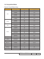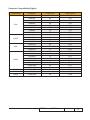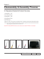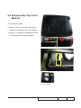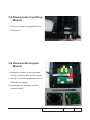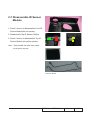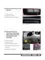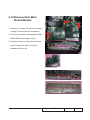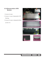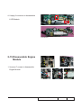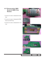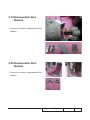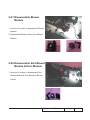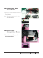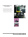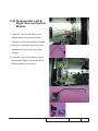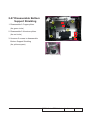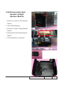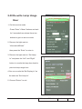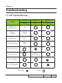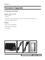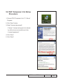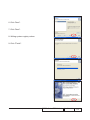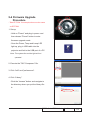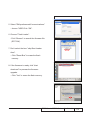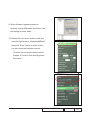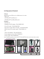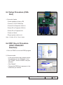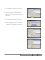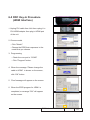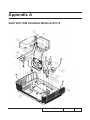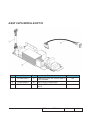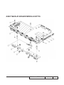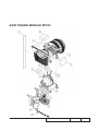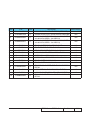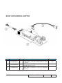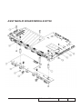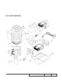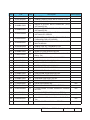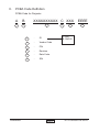
1
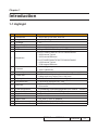
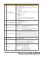
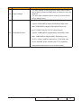
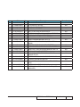
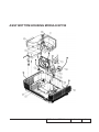
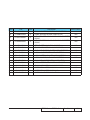
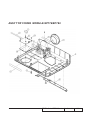
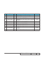
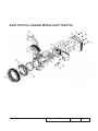
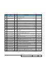
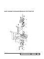
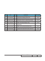
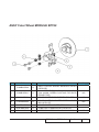
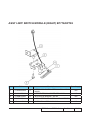
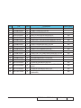
SERVICE MANUAL
EP776/EP782/EP776W/TX776/TX776W/OPX4100/TX782/
TX782W/OPX4800/EP782W
Date
Revise Version
Description
2008.02.29
V1.0
Initial Issue
2008.03.25
V2.0
Modify Chapter 1
V3.0
Add extended models
(EP776W/TX776/TX776W/OPX4100/TX782/TX782W/
OPX4800/EP782W)
2008.05.26
Copyright May,2008. All Rights Reserved P/N: 36.88E01G001
Emy
SI :
Yoyo
TSE:
Check:
Approved:
Preface
This manual is applied to EP776/EP782/EP776W/TX776/TX776W/OPX4100/TX782/
TX782W/OPX4800/EP782W projection system. The manual gives you a brief description
of basic technical information to help in service and maintain the product.
Your customers will appreciate the quick response time when you immediately identify
problems that occur with our products. We expect your customers will appreciate the
service that you offer them.
This manual is for technicians and people who have an electronic background. Please
send the product back to the distributor for repairing and do not attempt to do anything that
is complex or is not mentioned in the troubleshooting.
Notice:
The information found in this manual is subject to change without prior notice. Any
subsequent changes made to the data herein will be incorporated in future edition.
EP776 Series/EP782 Series Service Manual
Copyright May.2008
All Rights Reserved
Manual Version 3.0
EP776 Series/EP782 Series Confidential
1
1
1
1
1
1
1
1
1
1
1
1
EP776W(TX776W)&EP782 (TX782,OPX4800)Comparison List
EP776W(TX776W)
EP782 (TX782,OPX4800)
DC.88E02G001
A D.C. EP776 WITH
1
DC.88B01G001 A
D.C. EP782
WIRELESS
75.88B10G001
A BUY ASSY WIRELESS PCBA MODULE
70.88E20GR01
A
OSRAM 280W
1
70.88B22GR01 B
PHILIPS 330W
LAMP DRIVER
LAMP DRIVER
FOR EP7
FOR E
SP.88E01GC01
A
LAMP MODULE
1
SP.88B01GC01 B LAMP MODULE
FOR PROJECTOR
FOR PROJECEP77
TOR EP78
70.88E24GR01
D ASSY PCBA MAIN 1
70.88B24GR01 D
ASSY PCBA
BD MODULE FOR
MAIN BD MODU
ULE FOR E
70.88E11GR01
C
ASSY ENGINE
1
70.88B21GR01 C
ASSY ENGINE
MODULE EP776
MODULE EP782
(SERV
(SERV
70.88E10GR01
A
ASSY COLOR
1
70.88B23GR01
A
ASSY COLOR
WHEEL MODULE
WHEEL MODEP776
ULE EP782
75.85H14G001
B ASSY LVPS LITE1
75.88B07G001
A
MATRITEK
ON HD81
350W LVPS FOR
EP782(A
75.88E01G002
A BUY ASSY INTER- 1
75.88B02G002
A
BUY ASSY
RUPT SWITCH
INTERRUPT
MODU
SWITCH MODU
1
49.89K01G001
A
SUNON GB1205PKV1-8AY
50X50X20
75.88E02G001
A BUY ASSY THER1
75.88B04G001
A
BUY ASSY
MAL SWITCH
THERMAL
MODULE
SWITCH MODULE
35.88E01G001
A
LAMP WARNING
1
35.88B04G001
A LAMP WARNING
LABEL 280W PC
LABEL 330W PC
EP7
EP7
75.88B14G012
A
BUY ASSY IO
1
75.88B14G003
A
BUY ASSY IO
COVER MODULE
COVER MODWITH
ULE FOR E
EP776 Series/EP782 Series
Confidential
1
1
1
1
1
1
1
1
1
1
EP776W(TX776W)&EP782W(TX782W) Comparison List
EP776W(TX776W)
EP782W(TX782W)
DC.88E02G001 A
D.C. EP776 WITH
1 DC.88B02G001 A
D.C. EP782
WIRELESS
WITH WIRELESS
70.88E20GR01 A
OSRAM 280W LAMP
1 70.88B22GR01 B PHILIPS 330W
DRIVER FOR EP7
LAMP DRIVER
FOR E
SP.88E01GC01 A
LAMP MODULE FOR
1 SP.88B01GC01 B LAMP MODULE
PROJECTOR EP77
FOR PROJECTOR EP78
70.88E24GR01 D ASSY PCBA MAIN BD
1 70.88B24GR01 D
ASSY PCBA
MODULE FOR U
MAIN BD MODULE FOR E
70.88E11GR01 C
ASSY ENGINE MOD1 70.88B21GR01 C ASSY ENGINE
ULE EP776 (SERV
MODULE
EP782 (SERV
70.88E10GR01 A ASSY COLOR WHEEL 1 70.88B23GR01 A ASSY COLOR
MODULE EP776
WHEEL MODULE EP782
75.85H14G001 B
ASSY LVPS LITEON
1
75.88B07G001 A
MATRITEK
HD81
350W LVPS
FOR EP782(A
75.88E01G002 A
BUY ASSY INTER1
75.88B02G002 A
BUY ASSY
RUPT SWITCH MODU
INTERRUPT
SWITCH MODU
75.88E02G001 A BUY ASSY THERMAL
1
75.88B04G001 A
BUY ASSY
SWITCH MODULE
THERMAL
SWITCH MODULE
35.88E01G001 A
LAMP WARNING LA1
35.88B04G001 A LAMP WARNBEL 280W PC EP7
ING LABEL
330W PC EP7
EP776 Series/EP782 Series Confidential
EP776W(TX776W)&EP776(TX776,OPX4100) Comparison List
EP776W(TX776W)
EP776(TX776,OPX4100)
1 DC.88E02G001 A D.C. EP776 WITH WIRE- 1 DC.88E01G001 A
D.C. EP776
LESS
1 75.88B10G001 A BUY ASSY WIRELESS
PCBA MODULE
1 75.88B14G012 A BUY ASSY IO COVER
1 75.88B14G003 A BUY ASSY IO
MODULE WITH
COVER MODULE FOR E
EP776 Series/EP782 Series
Confidential
Table of Content
Chapter 1
Introduction
Highlight
1-1
Compatible Mode
1-3
Chapter 2 Disassembly Process
Equipment Needed & Product Overview
2-1
Disassemble Lamp Cover Module
2-2
Disassemble Lamp Module
2-2
Disassemble Top Cover Module
Disassemble Front Ring Module Disassemble Keypad Module
Disassemble IR Sensor Module
Disassemble Rear Cover Module Disassemble Top Shielding & Wireless Module
Disassemble Main Board Module
Disassemble Network Module
Disassemble IO Board Module
2-8
Disassemble Fan Module
2-9
Disassemble LVPS Module
2-10
Disassemble Engine Module
2-11
Disassemble Color Wheel Module
2-13
Disassemble DMD Board & DMD Chip Module
2-14
Disassemble Zoom Ring & Zoom Ring Base & Focus Ring 2-15
2-3
2-4
2-4
2-5
2-6
2-6
2-7
2-8
Disassemble Rod Module
2-16
Disassemble Duct Module
2-16
Disassemble Blower Module
2-17
EP776 Series/EP782 Series Confidential
Chapter 3
2-17
Disassemble Wind Tunnel Module
2-18
Disassemble Honeycombed Module
2-18
Disassemble Lamp Driver Module
2-19
Disassemble Left & Right Limit Switch Module
2-20
Disassemble Bottom Support Shielding
2-21
Disassemble Rear Speaker & Right Speaker Module
2-22
Rod Adjustment
2-23
Re-write Lamp Usage Hour
2-24
Troubleshooting
Chapter 4
Disassemble Rod Blower Module & Duct Module
LED Lighting Message
Main Procedure
3-1
3-2
Function Test & Alignment Procedure
Test Equipment Needed
4-1
Service Mode
4-1
OSD Reset
4-1
Test Condition
4-2
Test Inspection Procedure
4-3
PC Mode
4-3
Video Performance
4-7
Optical Performance Measure
4-8
Network Function Test
4-10
Wireless Function Test
4-12
Other
4-16
Chapter 5
Firmware Upgrade EP776 Series/EP782 Series
Confidential
Equipment Needed
5-1
DLP Composer Lite Setup Procedure
5-2
USB Driver Upgrade Procedure
5-4
Firmware Upgrade Procedure
5-5
Chapter 6 EDID Upgrade
EDID Introduction
6-1
Equipment Needed
6-2
Setup Procedure
6-3
DDC Key-In Procedure (VGA1,VGA2,DVI Interface)
6-3
DDC Key-In Procedure (HDMI Interface)
6-7
Appendix
��������� A���������������
���������������������������I
Appendix B
Serial Number System Definition PCBA Code Definition
XXXV XXXVI
EP776 Series/EP782 Series Confidential
Chapter 1
Introduction
1-1 Highlight
No
Item
Description
1
Dimensions
- 393.2*302.6*136.4mm, with foot
2
3
4
5
6
Weight
Tilt Angle
Power Supply
Keystone correction
DMD
7
Brightness
8
Contrast
9
Uniformity
10
Throw ratio
11
12
Displayable colors
Projection lens
13
Lamp life
14
15
16
17
18
19
20
Color temperature
Projection Screen Size
Projection distance
Offset
Aspect ratio
Chips set
De-interlace and Scalar
- <12lbs (5.45kg)
- >7°
- 100V ~ 240V + 10% 50~60Hz
- Manual Vertical-keystone +/- 16 degrees
- Single 0.7” XGA DarkChip3, 2xLVDS, type A
For EP776/EP776W/TX776/TX776W/OPX4100
- 3600 lumens Typical
- 3250 lumens Minimum
For EP782/EP782W/TX782/TX782W/OPX4800
- 4100 lumens Typical
3700 lumens Minimum
- 2000:1 (Typical)
- 1500:1 (Minimum)
- 60% (minimum)
- 1.57 ~ 1.89:1 with optional Add-on Short Throw (Wide
0.83x) and Long Throw (Tele 1.25x) lens
- 134.2 million colors 512 shades of gray
- F/2.52-2.79; f22.55-27.06 : 1.2x
- 2000 hrs (BRIGHT), 3000hrs (STD) 50% survival rate with
50% lumen
- Low/Mid/High selectable(adjustable from 5000ºK – 9500ºK)
- Adjustable 39.1’’ to 313.5”.(Diagonal)
- 1.5 – 10 meter
- 110% +/-10%
- 4:3, 16:9 -I, 16:9 –II, Window
- DDP2230/DAD2000/PMD1000
- DDP2230 w/. Brilliant Color ™
EP776 Series/EP782 Series Confidential
1-
No
Item
21
Inputs signal
������������
spec.
22
Outputs signal
������������
spec.
23
Signal support
24
Power consumption
25
Color wheel
26
Lamp
27
Temperature
Description
- 1x DVI-I (connector) (accept DVI-D signal) with HDCP
- 1x HDMI with HDCP
- 2x VGA (D-sub 15) (support RGB/YPbPr, and only VGA1
support SCART )
- 1x S-Video
- 1x Composite
- 5x Audio-In (for following video inputs: DVI, VGA1, VGA2,
S-Video and Composite)
- 1x RS232
- 1x RJ-45 LAN
- 1x USB
- 2x IR Remote-Control Receivers (top and front)
- 1x Optional Built-in Wireless Module(For EP776W/
EP782W)
- 1x VGA-Out (D-sub 15)
- 1x Audio-Out (φ3.5mm phone jack)
- 2x 3W speakers
- 1x 12V relay
- NTSC:
M (3.58MHz), 4.43 MHz, 480i
- PAL:
B, D, G, K, I, M, N
- SECAM:
B, D, G, K, K1, L
- SDTV/HDTV: 480i/p, 576i/p, 720p@50Hz/60Hz, 1080i@
50/60Hz,1080p@50Hz/60Hz.
Full Mode:
- 400 Wmax(EP776/EP776W/TX776/TX776W/OPX4100)
- 460 Wmax(EP782/EP782W/TX782/TX782W/OPX4800)
Eco Mode:
- 330w (Max) (EP776/EP776W/TX776/TX776W/OPX4100)
- 375w (Max) (EP782/EP782W/TX782/TX782W/OPX4800)
- 5 segments
- R80Y30G84W90B76
- EP776/EP776W/TX776/TX776W/OPX4100
280W lamp (Osram, requires BRIGHT/STD mode)
- EP782/EP782W/TX782/TX782W/OPX4800
330W lamp (Philips, requires BRIGHT/STD mode)
- Operating 5-35°C, 80% humidity
Storage: 20 - 60°C, 80% humidity
Altitude: 5 - 35°C @ 0 – 2500 ft
5 - 30°C @ 2500 – 5000 ft
5 - 25°C @ 5000 – 10,000 ft
Maximum storage altitude 40,000 ft
EP776 Series/EP782 Series
Confidential
1-
No
Item
28
Light Leakage
Description
- The light leakage of halo around the image shall be speci
fied in quality section but DMD mask or aperture in lens are
required
- The stray light outside the active region is under 0.8lux at
60” full black screen
For EP782/EP782W/TX782/TX782W/OPX4800
- Typical :37dB/33dB for Bright(330W)/Std(270W) mode
Max :39dB/35dB for Bright(330W)/Std(270W) mode
For EP776/EP776W/TX776/TX776W/OPX4100
29
Operational Noise
- Typical : 32dB/30dB for Bright(280W) /Std(230W) mode
Max : 34dB/32dB for Bright(280W) /Std(230W) mode
(at 23+/-2 deg C ambient temperature, 7200 RPM color
wheel rotational speed, following ISO 7779 regulation,
A-weighted sound pressure level measurement)
EP776 Series/EP782 Series
Confidential
1-
1-2 Compatible Mode
Computer Compatibility (Analog)
Compatibility
Resolution
V-Sync [Hz]
H-Sync [KHz]
640x350
70
31.5
640x350
85
37.9
640x400
85
37.9
640x480
60
31.5
640x480
72
37.9
640x480
75
37.5
720x400
70
31.5
720x400
85
37.9
800x600
800x600
800x600
800x600
1024x768
56
60
72
75
60
35.2
37.9
48.1
46.9
48.4
1024x768
70
56.5
WXGA
SXGA+
UXGA
1024x768
1152x864
1152x864
1152x864
1152x864
1280x1024
1280x1024
1280x1024
1280x960
1280 x 800
1400x1050
1600x1200
75
60
70
75
85
60
75
85
60
60
60
60
60.0
53.5
63.8
67.5
77.1
63.98
79.98
91.1
60.0
49.68
63.98
75.00
MAC LC 13”
640x480
66.66
34.98
MAC II 13”
MAC 16”
MAC 19”
MAC
MAC G4
i Mac DV
i Mac DV
i Mac DV
640x480
832x624
1024x768
1152x870
640x480
1024x768
1152x870
1280x960
66.68
74.55
75
75.06
60
75
75
60
35
49.725
60.24
68.68
31.35
60
68.49
60.0
VGA
SVGA
XGA
SXGA
EP776 Series/EP782 Series
Confidential
1-
Computer Compatibility (Digital)
Compatibility
VGA
SVGA
XGA
SXGA
WXGA
SXGA+
UXGA
Resolution
V-Sync [Hz]
H-Sync [KHz]
640x350
70
31.5
640x350
85
37.9
640x400
85
37.9
640x480
60
31.5
640x480
72
37.9
640x480
75
37.5
720x400
70
31.5
720x400
85
37.9
800x600
800x600
800x600
800x600
1024x768
56
60
72
75
60
35.2
37.9
48.1
46.9
48.4
1024x768
70
56.5
1024x768
1152x864
1152x864
1152x864
1152x864
1280x1024
1280x1024
1280x1024
1280 x 960
1280 x 800
1400x1050
1600x1200
75
60
70
75
85
60
75
85
60
60
60
60
60.0
53.5
63.8
67.5
77.1
63.98
79.98
91.1
60.0
49.68
63.98
75.00
EP776 Series/EP782 Series
Confidential
1-
Chapter 2
Disassembly & Assembly Process
2-1 Equipment Needed & Product Overview
1. Screw Bit (+) :107
2. Hex Sleeves 5mm
3. Screw Bit (+) :102
4. Hex Sleeves 7mm
5. EP776W unit
* Before you start: This process is protective level II. Operators should wear electrostatic chains.
* Note: If you need to replace the main board, you have to get into service mode and record the
lamp usage hour. please refer to section 2-30.
Note:EP776 Series&EP782 Series are the same,here we take EP776W as an example.
EP776 Series/EP782 Series Confidential
2-
2-2 Disassemble Lamp
Cover Module
1. Unscrew 1 screw
2. Press 2 tenons to disassemble Lamp
Cover Module
Lamp Cover Module
2-3 Disassemble Lamp
Module
1. Unscrew 2 screws to disassemble Lamp
Module
Note:You should cooling the unit at least 30
minutes,then you can disassemble
the lamp module
Lamp Module
EP776 Series/EP782 Series Confidential
2-
2-4 Disassemble Top Cover
Module
1. Unscrew 5 screws
2. Press 1 tenon on the right side and 2
tenons on the left side (As red square)
3. Unplug 1 connector to disassemble Top
Cover Module (As yellow square)
Top Cover Module
EP776 Series/EP782 Series Confidential
2-
2-5 Disassemble Front Ring
Module
1. Unscrew 1 screw to disassemble Front
Ring Module
2-6 Disassemble Keypad
Module
1. Unscrew 4 screws (As red circle)and
unplug 2 connectors(As yellow square)
2. Unplug 1 connector to disassemble FPC
Cable(As red square)
3. Disassemble all components of the
Keypad Module
EP776 Series/EP782 Series Confidential
2-
2-7 Disassemble IR Sensor
Module
1. Press 2 tenons to disassemble Front IR
Sensor Module(As red square)
2. Disassemble Top IR Sensor Rubber
3. Press 2 tenons to disassemble Top IR
Sensor Module (As yellow square)
Note: - Disassemble the cable from plastic
tie(As green square)
IR Sensor Module
EP776 Series/EP782 Series Confidential
2-
2-8 Disassemble Rear Cover
Module
1. Unscrew 3 screws
2. Disassemble an aerial
3. Disassemble Rear Cover Module
Rear Cover Module
2-9 Disassemble Top
Shielding & Wireless
Module(For EP776W/
EP782W/TX776W/
TX782W)
1. Unscrew 16 screws
2. Unscrew 1 screw
3. Disassemble Wireless Module
4. Take off Interrupt Switch from Top
Shielding
5. Disassemble Top Shielding
Wireless Module
Top Shielding
EP776 Series/EP782 Series Confidential
2-
2-10 Disassemble Main
Board Module
1. Unscrew 5 screws (As yellow circle)and
unplug 9 connectors(As red square)
2. Unscrew 4 screws to disassemble Main
Board Module (As green circle)
3. Unscrew 10 Hex screws (As red circle)
and 2 screws (As yellow circle) to
disassemble Iron cut
Main Board Module
EP776 Series/EP782 Series Confidential
2-
2-11 Disassemble Network
Module
1. Unscrew 1 screw to disassemble
Network Module
2-12 Disassemble IO Board
Module
1. Unscrew 2 screws
2. Disassemble 1 Copper Pillar
3. Disassemble IO Board from Main Board
Module
IO Board Module
Main Board Module
EP776 Series/EP782 Series Confidential
2-
2-13 Disassemble Fan
Module
1. Unscrew 2 screws to disassemble Fan
Module
2. Unscrew 3 screws to disassemble Fan
Shielding from Fan Module
EP776 Series/EP782 Series Confidential
2-
2-14 Disassemble LVPS
Module
1. Unscrew 4 screws
2. Unscrew 1 screw to disassemble LVPS
Shielding
3. Unscrew 3 screws to disassemble Mylar
and Iron Cut
EP776 Series/EP782 Series Confidential
2-10
4. Unplug 2 connector to disassemble
LVPS Module
LVPS Module
2-15 Disassemble Engine
Module
F
C
A
G
B
E
1. Unscrew 7 screws to disassemble
Engine Module
A
B
C
E
D
EP776 Series/EP782 Series Confidential
2-11
2. Unplug 1 connector to disassemble Limit
Switch
3. Unscrew 1 screw to disassemble
Thermal Switch
Thermal Switch
EP776 Series/EP782 Series Confidential
2-12
2-16 Disassemble Color
Wheel Module
1. Unscrew 2 screws to disassemble Color
Wheel Module
2. Unscrew 1 screw to disassemble Photo
Sensor Module from Color Wheel
Module
Color Wheel Module
Photo Sensor Module
EP776 Series/EP782 Series Confidential
2-13
2-17 Disassemble DMD
Board & DMD Chip
Module
1. Unscrew 4 screws to disassemble Heat
Sink
2. Unscrew 4 screws to disassemble DMD
Board and DMD Chip
3. Unscrew 2 screws to disassemble 2 Iron
Cuts
EP776 Series/EP782 Series Confidential
2-14
2-18 Disassemble Zoom
Ring & Zoom Ring Base
& Focus Ring
1. Unscrew 2 screws to disassemble Zoom
Ring & Zoom Ring Base
2. Unscrew 3 screws to disassemble Focus
Ring
EP776 Series/EP782 Series Confidential
2-15
2-19 Disassemble Rod
Module
1. U
nscrew 5 screws to disassemble Rod
Module
2-20 Disassemble Duct
Module
1. U
nscrew 4 screws to disassemble Duct
Module
EP776 Series/EP782 Series Confidential
2-16
2-21 Disassemble Blower
Module
1. Unscrew 2 screws to disassemble Blower
Module
2. Disassemble Blower Holder from Blower
Module
2-22 Disassemble Rod Blower
Module & Duct Module
1. Unscrew 4 screws to disassemble Rod
Blower Module & Duct Module & Blower
Holder
EP776 Series/EP782 Series Confidential
2-17
2-23 Disassemble Wind
Tunnel Module
1. Unscrew 3 screws to disassemble Wind
Tunnel Module
Note: - The screw (As yellow circle) is in the
front side of the unit
2-24 Disassemble
Honeycombed Module
1. Unscrew 2 screws to disassemble
Honeycombed Module
EP776 Series/EP782 Series Confidential
2-18
2-25 Disassemble Lamp
Driver Module
1. Unscrew 4 screws (As red circle)to
disassemble Lamp Driver Module
2. Unscrew 2 screws (As yellow circle)to
disassemble Lamp Driver Support
Lamp Driver Module
Lamp Driver Support
EP776 Series/EP782 Series Confidential
2-19
2-26 Disassemble Left &
Right Interrupt Switch
Module
1. Unscrew 1 screw (As red circle)to
disassemble Left Interrupt Switch
Module & Left Interrupt Switch Holder
2. Unscrew 1 screw(As yellow circle) to
disassemble Right Interrupt Switch
Module
3. Unscrew 1 screw (As green circle)to
disassemble Right Interrupt Switch &
Plastic Holder & Iron Holder
EP776 Series/EP782 Series Confidential
2-20
2-27 Disassemble Bottom
Support Shielding
1. Disassemble 2 Copper pillars
(As green circle)
2. Disassemble 5 Aluminum pillars
(As red circle)
3. Unscrew 5 screws to disassemble
Bottom Support Shielding
(As yellow square)
Bottom Support Shielding
EP776 Series/EP782 Series Confidential
2-21
2-28 Disassemble Rear
Speaker & Right
Speaker Module
1. Unscrew 2 screws on Rear Speaker
Module
2. Tear off EMI Shielding
3. Unscrew 2 screws on Right Speaker
Module
4. Disassemble Rear & Right Speaker
Module
5. The disassembly is completed
EP776 Series/EP782 Series Confidential
2-22
2-29 Rod Adjustment
1. Environment adjustment
- The distance between the engine and the
screen is 1.91M
- This process should be done at a dark
environment. (under 5 Lux)
2. Procedure adjustment
- Change the screen to “white screen.”
- Adjust the screws by using the rod on
the engine module to readjust the image.
(adjust until the yellowish or bluish parts
disappeared.)
3. Abnormal image inspection
- It should not have any abnormal color at the
rim of the image by estimating through the
eyes.
Note: - To avoid over adjust the rod.
- After the opration,please use the glue to
fixed the screws.
EP776 Series/EP782 Series Confidential
2-23
2-30 Re-write Lamp Usage
Hour
1. Get into service mode
- Press “Enter”+“Menu” buttons and wait
for 2 seconds then release these two
buttons to get into service mode.
2. Remove the light mark to
“Information&Reset”
then press the “Enter” to enter in.
3. Remove the light mark to “Set Lamp
hr” and press the “Left” and “Right”
botton to re-write the lamp hour back to
previous lamp usage hour.
4.You can re-write the“Set Display hr” as
the same as “Set Lamp hr”.
5. Choose “Return” to exit.
EP776 Series/EP782 Series Confidential
2-24
Chapter 3
Trobleshooting
3-1 LED Lighting Message
Message
Power-LED
Temp-LED
Lamp-LED
Blue/Red
Red
Red
Standby State
(Input power cord)
Red
Power on
(Warming)
Flashing
Blue
Lamp Lighting
Blue
Power off (Cooling)
Flashing
Red
Error (Over Temp)
Flashing
(0.5s on, 0.5s off)
Error (Fan fail)
Error (Lamp fail)
Error (C/W Shut Down)
Steady Light:
No Light:
EP776 Series/EP782 Series Confidential
3-
3-2 Main Procedure
No
Procedure
Symptom
- Ensure the Power Cord and AC Power Outlet are securely
connected
- Check Lamp Cover , Interrupt Switch and Interlock Switch
1
No Power
- Ensure all connectors are securely connected and aren’t
broken
- Check Lamp Driver
- Check LVPS
- Check Main Board
- Check LED Status
a. Lamp LED Light
- Check Lamp
- Check Lamp Driver
- Check Color Wheel
- Check Main Board
2
Auto Shut Down
b. Temp LED Light
- Check Thermal Switch
- Check Fan
- Check Main Board
c. Color Wheel
- Check Color Wheel
- Check Photo Sensor
EP776 Series/EP782 Series Confidential
3-
No
Procedure
Symptom
- Ensure the Signal Cable and Source work
(If you connect multiple sources at the same time, use the
“Source” button on the control panel to swtich)
- Ensure all connectors are securely connected and aren’t
broken
3
No Image
- Check Wireless Module (Only at the time when you are using
WLAN to transfer the signal) ����������������������������
(For EP776W/ EP782W/TX776W/
TX782W)
- Check Main Board
- Check I/O Board
�����
- Check DMD Chip
- Check Engine Module
- Ensure all connectors are securely connected and aren’t
broken
4
No Light On
- Check Lamp Module
- Check Lamp Driver
- Check LVPS
- Check Main Board
5
Machanical Noise
- Check Color Wheel
- Check Fan Module
- Check if the Main Board and the DMD Board are
assembled properly
6
Line Bar/Line Defect
- Check Main Board
- Check DMD Board
- Check DMD Chip
EP776 Series/EP782 Series Confidential
3-
No
Procedure
Symptom
- Do “Reset(All data)” of the OSD Menu
- Ensure that the signal cables and source are work as well
7
Image Flicker
- Check Lamp Module
- Check Color Wheel
- Check DMD Board
- Check Main Board
- Do “Reset(All data)” of the OSD Menu
8
Color Abnormal
- Adjust Color Wheel Index
- Check Main Board
- Check Color Wheel
- Ensure the projection screen without dirt
9
Poor Uniformity/
Shadow
- Ensure the projection lens is clean
- Ensure the Brightness is within spec
- Check rod alignment
- Check Engine Module
- Ensure the projection screen without dirt
10
Dead Pixel/Dust
(Out of spec.)
- Ensure the projection lens is clean
- Clean DMD Chip and Engine Module
- Check DMD Chip
- Check Engine Module
- Ensure that the signal cables and source work as well
11
Garbage Image
- Check Main Board
- Check DMD Board
EP776 Series/EP782 Series Confidential
3-
No
Procedure
Symptom
- Remote Control
a.Check Battery
b.Check Remote Controller
12
Remote Control/
Control Panel Failed
c.Check IR Sensor Board
d.Check Main Board
- Control Panel
a.Check FPC
b.Check keypad
c.Check Main Board
- Do “Reset(All data)” of the OSD Menu
13
Function Abnormal
- Check Main Board
- Check DMD Board
- Ensure that the signal cables and source are work as well
14
Audio Abnonrmal
- Check Speaker Module
- Check Main Board
- Ensure you have set up the right IP address and the
15
Network Fail
connection is OK(Network green LED should be light up)
- Check the Network Module
- Check the Main Board
- Ensure you have set up the PC Setting and the
16
Wireless Fail
(For EP776W/
EP782W/TX776W/
TX782W)
connection is OK(Wireless green LED should be light up)
- Ensure you have reset the wireless module (Please refer to
4-10)
- Check the Wireless Module
- Check the Main Board
EP776 Series/EP782 Series Confidential
3-
Chapter 4
Function Test & Alignment Procedure
4-1 Test Equipment Needed
- IBM PC with XGA resolution
- DVD player with Multi-system, equipped “Component”, “S-Video”
, “Composite” and "HDMI."
- HDTV Source (480P, 720P, 1080i)
- Minolta CL-100
- Quantum Data 802B or CHROMA2327 (Color Video Signal & Pattern Generator)
- After changing parts, check the information below.
4-2 Service Mode
1. Turn on the projector
2. Do the following actions sequentially to enter service mode menu
(1) Press “Enter”+“Menu” button wait for 2 seconds.
(2) Service Mode will be shown.
(3) Press"Menu" botton to leave the Service Mode after all.
4-3 OSD Reset
1. After final QC step, we have to erase all saved change again and restore the OSD
default setting. The following actions will allow you to erase all end-users' settings and
restore the default setting:
(1) Please enter OSD menu.
(2) To execute "Reset" function.
EP776 Series/EP782 Series Confidential
4-
4-4 Test Condition
- Circumstance brightness: Dark room less than 5.0 lux.
- Inspection distance: 1.8m~2.5m functional inspection.
- Screen size: 60 inches diagonal.
- After repairing each (EP776 Series/EP782 Series), the unit should be run-in (refer to the
table below).
Symptom
Normal repair
NFF
Auto shutdown
Run-in Time
2 hours
4 hours
6 hours
- Enter Burn-In Mode
* Cycle setting is based on the defect symptoms. ie: If it is NFF, the run-in time is 4 hours. You have
to set the lamp on for 50 min. and lamp off for 10 min for 4 cycles.
Press "Enter"+"Menu" wait for 2 seconds
Choose Burn-In Test > enter
Lamp On (Min)
Press right key to adjust the time (50)
Lamp Off (Min)
Press right key to adjust the time (10)
Set burn in cycle
Press right key to adjust the cycle
After setting up the time, choose Burn-In mode and hit enter
EP776 Series/EP782 Series Confidential
4-
Screen Defects (While replacing DMD Chip, DMD BD and MB)
< Figure: Zone A &B Definition >
Defect specification table
Order
Symptom
Pattern
Black pattern
1
Bright pixel ( dots)
2
Dark pixel(dots)
White pattern
3
Unstable pixel (dots)
Any pattern
4
Adjacent dark pixel
(dots)
Any pattern
5
Dark blemish (Dirty)
Blue 60 pattern
6
Bright blemish (Dirty)
Gary 30 pattern
7
Bright dot on frame
Black pattern
( IRE=O)
Criteria
A+B=0
A+B=6
A+B=1
A+B=0
A+B=3
(diameter <1/2 inch)
A+B=3
(diameter <1/2 inch)
2
EP776 Series/EP782 Series Confidential
4-
4-5 Test Inspection Procedure
Change parts/
Update
M/B
FW
Version Update
v
v
Color Wheel Index
v
Color Wheel Lamp Module
Rod
Engine
v
v
Wireless
Module
v
Reset lamp hour
v
OSD Reset
v
EDID
v
Re-write Lamp
Hour Usage
v
v
ROD Adjust
Wireless Module
Reset
v
Note:If Color appears ���������������
abnormal�������
after ����
M/B ������������������
changed,please do
Color Wheel index adjust.
4-6 PC MODE
1. Frequency and tracking boundry
Procedure - Test equipment: video generator.
- Test signal: analog 1024 x 768�����
@60Hz
- Test Pattern: general-1 or master
- Check and see if the image sharpness is wellperformed.
- If not re-adjust by the following steps:
(1) Select "Frequency" function to adjust the
total pixel number of pixel clock in one line
period.
(2) Select "Tracking" function and use right or
left arrow key to adjust the value to minimize
video flicker.
- Adjust Resync or Frequency/Tracking/H. Posi-
General-1
Master
EP776 Series/EP782 Series Confidential
4-
tion/V. Position to the inner screen.
Inspection item
-E
liminate visul wavy noise by Rsync, Frequency
- Check if there is noise on the screen.
- Horizontal and vertical position of the video
should be adjustable to the screen frame.
Criteria
or Tracking selection.
- If there is noise on the screen, the product is
considered as failure product.
- If there is noise on the screen, use auto or
manul “frequency” function or “tracking” function
to adjust the screen.
- The PC mode functionally sure be workable
include support format with frequency and auto
detected functional will be workable.
2. Light Leak
Procedure
- Test equipment: video generator.
-���������������������������������������
Test signal: analog 1024 x 768@60Hz��� - Test Pattern: gray 30 patterns
- Check if the light leaks.
* Light leak on reflective edge, eyecatcher, bondwires and exposed metal.
Inspection item
Gray 30
- Light leak check.
- Bright blemish (dirty).
Criteria
- The pattern cannot accept the color level of the
leakage is brighter than the grey 30 pattern.
- Ref. below table
Note: The defect criteria follows TI specification.
3. Blemish (Dark)
Procedure
- Test equipment: video generator.
�������������������������������������
- Test signal: analog 1024 x 768@60Hz
- Test Pattern: blue 60
Inspection item
- Dark blemish check.(dirty)
Criteria
- The bright blemish is unacceptable when it ap-
Blue 60
EP776 Series/EP782 Series Confidential
4-
pears on blue 60 pattern.
- Ref. below table
Note: The defect criteria follows TI specification.
4. Dead Pixel (Bright pixel)
Procedure
- Test equipment: video generator.
�������������������������������������
- Test signal: analog 1024 x 768@60Hz
- Test Pattern: full black
Inspection item
- Bright pixel check.
Note: Frame dimension under operative zone1
inch
Criteria
- Bright pixel is unacceptable.
- Ref. below table
Full black
Note: The defect criteria follows TI specification.
5. Dead Pixel (Dark pixel)
Procedure - Test equipment: video generator.
�������������������������������������
- Test signal: analog 1024 x 768@60Hz
- Test Pattern: full white
Inspection item
- Dead pixels check.
- White pattern (IRE=100)
- Adjacent dark pixel.
Criteria
- The number of the dead pixels should be less or
equal to 6 pixels.
- Adjacent pixel with each other is unacceptable.
- Ref. below table
Full white
Note: The defect criteria follows TI specification.
6. Focus test
Procedure
- Test equipment: video generator.
�������������������������������������
- Test signal: analog 1024 x 768@60Hz
- Test Pattern: full screen or MEME Sony
Inspection item
- Focus check
Full screen
EP776 Series/EP782 Series Confidential
4-
Criteria
-From screen 1.5 M via visual to check the focus,
look at the entire screen, focus shall be clear,
crisp, and sharp over the entire surface of the
display pattern. (Blur word on one of the corner
after adjustment is acceptable. However, the
word should at least be recognizable.)
MEME Sony
7. Color performance
Procedure
- Test equipment: video generator.
- Test signal: DVI (HDMI) 720p,1080i
- Test Pattern: Master, In focus II or SMPTE RP133
* Please refer to 4-2 to enter service mode.
Use 720P & 1080i signal, master pattern to do
HDTV test. Color cannot discolor to purple and
blue. If the test result is discoloration or flickering, please return the unit back to repair centers.
Inspection item
Criteria
Master
- Check if each color level is well-functioned.
- color saturations
- Screen appears normal. It should not have any
abnormal condition, such as lines appear on the
screen and so on.
- Color appears normal.
- It is acceptable to have few lines flashing at the
center and on the edge of 1080i image. However, rest of the image should appears stable.
- RGBW should all appear normal on the screen
and sort from R -G-B-W.
- Color levels should be sufficient and normal.
(the unidentified color levels on both left and
right sides should not over 8 color levels.)
- Grey level should not have abnormal color or
heavy lines.
- The PC mode functionally sure be workable
include support format with frequency and auto
detected functional will be workable
InFocus II
/ 64 gray RGBW
SMPTE RP-133
EP776 Series/EP782 Series Confidential
4-
4-7 Video Performance
1. CVBS
Procedure - Test equipment: DVD player
- Test signal: CVBS
Inspection item
- Video performance test
Inspection Distance - 1.8M ~2.5M
Criteria
- Check any abnormal color, line distortion or any
noise on the screen.
- Check the sound from speakers.
Motion video
2. S-Video
Procedure
- Test equipment: DVD player
- Test signal: S-Video
Inspection item
- Video performance test
Inspection Distance - 1.8M ~2.5M
Criteria
- Check any abnormal color, line distortion or any
noise on the screen.
- Check the sound from speakers.
3. HDTV/ Component
Procedure - Test equipment: DVD player
- Test signal: Ycbcr/YPbPr
Inspection item
- HDTV performance test
InspectionDistance - 1.8M ~2.5M
Criteria
- Check any abnormal color, line distortion or any
noise on the screen.
- Check the sound from speakers.
EP776 Series/EP782 Series Confidential
4-
4. Audio Test
Procedure - Test equipment: DVD player
- Test signal: CVBS
Inspection item
- Audio performance test
Inspection Distance - 1.8M ~2.5M
Criteria
- Check the sound from speakers.
- Check “Volume” is normal
- Check “Mute” is normal
5. HDMI Test
Procedure
- Test equipment: DVD Player with HDMI output
- Test signal: 720p,1080i,1080p
Inspection item
- HDMI performance test
Inspection Distance
- 1.8M ~2.5M
Criteria
- Ensure if the image is well performed and the
color can not discolor
.
4-8 Optical Performance Measure
Inspection Condition
- Environment luminance: 5 Lux
- Product must be warmed up for 3 minutes
- Distances from the screen: 1.9M
- Screen Size: 60 inches diagonal
- Reset to default before measurement
1. Test equipment
Procedure - Test equipment: video generator.
- Test signal:��������������������
analog 1024x768@60Hz
EP776 Series/EP782 Series Confidential
4-
2. Brightness
Procedure - Full white pattern
- Use CL100 to measure brightness values of P1~P13.
- Follow the brightness formula to calculate
brightness values.
☼ Brightness Formula
Avg. (P1~P9)*1.1m2
Criteria
- 1780 lumen (EP776 series)
- 2030 ��������������������
lumen (EP782 series)
Full white pattern
3. Ful On/Full Off Contrast
Procedure
- Full white pattern & full black pattern
- Use CL100 to measure brightness values of full
white pattern P5 & full black pattern B5 ( see image: full white)
- Follow Contrast formula to calculate contrast
values.
☼ Contrast Formula
P5/B5
note: P
5=center of white image
Criteria
Full black pattern
B5 = the center of black image.
- 1500:1
4. Uniformity
Procedure
- Full white pattern
- Use CL100 to measure brightness values of
P1~P13 (see image: full white).
- Follow the Uniformity formula to calculate
average values.
☼ Uniformity Formula
Avg.(P1,P3,P7,P9)
ANSI Uniformity����
=���
P5
- 60 %
Criteria
X100%
EP776 Series/EP782 Series Confidential
4-10
4-9 Network Function Test
1. Read Projector IP
- Press “Menu” to enter OSD Mode
- Use Left button to select “SETUP”,then press down button to move the light mark to “▼”,the picture A will be shown on screen.
- Choose “Network” then press “enter”,the picture B will be shown on screen,then write down the IP address.
A
B
EP776 Series/EP782 Series Confidential
4-11
2.Network Setting
- Open the “Local area connection”,choose properties
- Select “Internet protocol(TCP/IP)”
- Modify the IP address to 10.0.50.101,
and modify Subnet mask to 255.255.0.0
- Click “OK”
EP776 Series/EP782 Series Confidential
4-12
3.Read Projector Information
- Connect the PC and the Projector with LAN
Cable
- Click “Internet Explorer”
- Write the IE address:http://10.0.50.100
- Then the information will be shown on the web
4-10 Wireless Function Test
(ForEP776W/EP782W/
TX776W/TX782W)
1.Projector Setting
- Power on projector
- Wireless module reset:Press “Reset” button on
back cover for 5 seconds,then the LED will be
flashing to steady green light
- Press “Menu” to enter OSD Mode
- Use Left button to select “SETUP”,then press
down button to move the light mark to “▼”,the
picture A will be shown on screen.
EP776 Series/EP782 Series Confidential
4-13
- If the Wireless is “off” ,we must use the Left or
Right button to change it “On”.
- Press “menu” to Exit
- Press “source” button until the screen show
A
Wireless Logo
2. PC Setting
- Open the “Wireless Network connection”
- Select “WS-9211G”
- Set “Obtain an IP address automatically”
EP776 Series/EP782 Series Confidential
4-14
3. Download Software
- Click “Internet Explorer”
- Write the IE address:http://192.168.100.10
- Then the information will be shown on screen
- Click “Download Software”
- Click “Download” then we will download “WS-
9211G” file
4. Air Projection system setup procedure
- Click “WS-9211G” file
- Click “Next”
EP776 Series/EP782 Series Confidential
4-15
- “Searching” will be shown on screen
- Key in LOGIN CODE which shown on screen,
then the wireless module will working
EP776 Series/EP782 Series Confidential
4-16
4-11 Others
1. Functional Inspection
Keypad button
- All keypad buttons must operate
smoothly.
General- All OSD functions must be
checked for functionality. When
OSD menu is displayed, there
shall be no visible peaking,
ringing, streaking, or smearing
artifacts on the screen.
Factory Default
Display Size
- The factory settings (with appropriate centering, size, geometry
distortion, etc.) shall be displayed
upon “Recall” is selected from
OSD
- All preset modes shall expand to
full screen size using OSD Horizontal and Vertical Size controls
Display Data Channel (DDC) - The purpose of the DDC test is to
verify the DDC1/DDC2B operation of the projector and to verify
Plug & Play function.
Acoustic
- High pitch sound from cooling fan
and color wheel is unacceptable.
EP776 Series/EP782 Series Confidential
4-17
2. Check points for exterior and print pattern
Check item
Check point
text & pattern
missing letters & pattern or blurry prints are
unacceptable.
exterior
dirt, scrape, water ripples and uneven color are
unacceptable.
buttons
stuck buttons are unacceptable.
Focus ring
Focus ring is functioning smoothly.
Logo
missing logo, missing prints and blurry prints are
unacceptable
screw
elevator
All screw sure be fixed and in right type.
Elevator is well-functioned.
Stuck key is unacceptable.
pedestal
well-functioned
lamp cover
It should be locked in the correct place.
Plastic parts
Safety or warning
label
Connector
All plastic parts can not be brocken and damaged.
All safety and warning label should be visible,
including all contents.
All interface connector should be complete and
workable.
EP776 Series/EP782 Series Confidential
4-18
Chapter 5
Firmware Upgrade
5-1 Equipment Needed
Software : (DDP 2230- USB)
- DLP Composer
- Firmware
- Library V7.1 0330 (library file has to put in PC and set right path in step of 5-4-4
Firmware Upgrade Procedure)
Hardware :
- Projector
- Power cord (42.53506G002)
- USB Cable (42.87304G001)
- PC or Laptop
EP776 Series/EP782 ������
Series Confidential
5-
5-2 DLP Composer Lite Setup Procedure
1. Choose "DLP Composer Lite V7.1 Setup"
Program.
2. Click "Next" button.
3. Read "License Agreement".
-C
hoose "I accept and agree to be bound
by all the terms and conditions of this
License Agreement".
4. Click "Next".
5. Click "Next".
3
4
EP776 Series/EP782 Series Confidential
5-
6. Click "Next".
7. Click "Next".
8. Writing system registry values.
9. Click "Finish".
EP776 Series/EP782 Series Confidential
5-
5-3 USB Driver Upgrade
Procedure
1. set up
- Plug in Power cord to projector.
- Link PC USB port and projector USB port
by USB Cable.
2. Execute Program
(1) " Found new hardware wiszard" will be
(2)
(3)
appearred on the screen.
(2) Select "Install the software automatically
(Recommended)".
(3) Then click "Next".
3. Finish
- Click "Finish" to end the installation.
EP776 Series/EP782 Series Confidential
5-
5-4 Firmware Upgrade
Procedure
- Take EP776W for example,others are the same
as EP776W
1. Set-up
- Hold on "Power" and plug in power cord
then release "Power" button to enter
firmware upgrade mode.
- Once the Power, Temp and Lamp LED
light up, plug in USB cable into the
projector and link to the USB port of a PC.
Note: T
he system fan and the light will not
operated.
2. Execute the "DLP ComposeTM" file.
3. Click "edit" and "perferences".
4. Click “Library.”
- Click the “browse” button and navigate to
the directory where you put the library file
in.
EP776 Series/EP782 Series Confidential
5-
5. Select "Edit\preferences\Communications"
- choose "USB".Click "OK".
6. Choose "Flash Loader".
- Click "Browse" to search the firmware file.
(EP776W).
7. Don't select the item "skip Boot Loader
Area".
- Click "Reset Bus" to erase the flash
memory.
8. If the firmware is ready, click "start
download" to process the firmware
upgrade.
- Click "Yes" to erase the flash memory.
EP776 Series/EP782 Series Confidential
5-
9. When firmware upgrade process is
finished, unplug USB cable and power cord
and replug in power cable.
10. Restart the unit ,enter service mode and
move the light mark to “Information&Reset”
press the “Enter” button to enter in,then
you can check the firmware version.
(To enter service mode, please refer to
Chapter 4 Function Test and Alignment
Procedure.)
EP776 Series/EP782 Series Confidential
5-
Chapter 6
EDID Upgrade
6-1 EDID Introduction
Extended Display Identification Data is a VESA standard data format that contains basic
information about a display device and its capabilities, including vendor information,
maximum image size, color characteristics, factory pre-set timings, frequency range limits,
and character strings for the monitor name and serial number.
The information is stored in the display and is used to communicate with the system
through a Display Data Channel (DDC), which sites between the display device and the
PC graphics adapter. The system uses this information for configuration purposes, so the
monitor and system can work together.
Note: If a display device has digital input ports, like DVI or HDMI, but without EDID in its
main board, the display device will show no image while the input source is digital signal.
EP776 Series/EP782 Series Confidential
6-
6-2 Equipment Needed
Software
Note:There are two EDID,one is for HDMI,another is for others
- EDID .exe
- OPTOMA_EP776_0824A_A.ini
- OPTOMA_EP776_HDMI_0824A_A.ini
Hardware
- EP776W unit
- HDMI(M) to DVI(F) Adapter P/N:42.82B13G001
- DVI to DVI cable P/N:42.83N06G001
- RS-232 9 pin cable ( Male to Female) P/N:42.83C07G001
- EDID Fixture (JP3 must be closed) P/N:80.00001.001
- PC
- VGA to VGA cableX2 P/N:42.87305G102
- Power adapter for fixture P/N:47.57803G001
- Power cordX2 P/N:42.53506G002
Note: The EDID upgrade procedure for EP776 Series/EP782 Series are the same.Here, we take
EP776W as an example.
EP776 Series/EP782 Series Confidential
6-
6-3 Setup Procedure (VGA
Port)
P1
RS232 Cable
Adapter
JP2
1. Connect all ports
- Power adapter to fixture JP2
- Fixture P1 to PC COM Port
- Fixture P4 to Projector VGA1 in
P2
P4
VGA-VGA Cable
- Fixture P2 to Projector VGA2 in
P3
DVI-DVI Cable
- Fixture P3 to Projector DVI
- Power on fixture
- Plug in power cord to unit
Note: Confirm JP3 is “Close” status.
6-4 DDC Key-In Procedure
(VGA1,VGA2,DVI
Interface)
1. Click on "EDID" to execute EDID program
2. Choose model
- In the port selection bar, please choose
the port that you use. Example: if you
use "COM2," choose COM2 in the port
selection.
- Click "Model."
- Choose the EDID that responses to the
model that you choose.
2
EP776 Series/EP782 Series Confidential
6-
(1)
3. Programming
(4)
(1) Key in the serial number into the
barcode blank space.
(2)
(2) In"Write Source Select"item,select
(3)
“VGA1” , “VGA2” and “DVI”.
(3) Check the com port is “COM2”
(4) Click "Program" button.
4. When the message “Please change the
“
cable to VGA1” is shown on the screen,
click “OK” button.
5. “Run”message will appear on the screen.
6. When the message “Please change
the cable to VGA2” is shown on the
screen,click “OK” button.
“
EP776 Series/EP782 Series Confidential
6-
7. “Run”message will appear on the screen.
8. When the message “Please change the
cable to DVI” is shown on the screen,click
“OK” button.
9. “Run”message will appear on the screen.
10. When the EDID program is completed, a
message "OK" will appear on the screen.
“
EP776 Series/EP782 Series Confidential
6-
11. Read EDID information
“
- In the Read item,select “Analog” and
“Trans”.
- Please press “Read” button.
- EDID Informations will show the
result.(As the yellow square)
12. Read EDID information
- In the Read item,select “Digital” and
“
“Trans”.
- Please press “Read” button.
- EDID Informations will show the result.
(As the red square)
Note:(1) Both VGA1 and VGA2 need to read
(2) While read VGA1(VGA2) EDID
Information,please unplug VGA
cable of VGA2(VGA1)
EP776 Series/EP782 Series Confidential
6-
6-5 DDC Key-In Procedure
(HDMI Interface)
1. Unplug DVI cable from Unit then replug it in
DVI-HDMI adapter then plug in HDMI port
of the unit
2. Choose model
- Click "Model."
- Choose the EDID that responses to the
model that you choose.
3. Programming
- Check the com port is “COM2”
- Click "Program" button.
4. When the message “Please change the
cable to HDMI” is shown on the screen,
click “OK” button.
5. “Run”message will appear on the screen.
6. When the EDID program for HDMI is
completed, a message "OK" will appear
on the screen.
EP776 Series/EP782 Series Confidential
6-
“
7. Read EDID information
- In the Read item,select “Digital” and
“Trans”.
- Please press “Read” button.
- EDID Informations will show the result.
EP776 Series/EP782 Series Confidential
6-
Appendix A
ASSY BOTTOM HOUSING MODULE EP776
EP776 Series/EP782 Series Confidential
Item
1
P/N
51.87Y20G001
Rev
A
2
61.83J14G001
A
3
4
5
61.89532G001
61.87340G001
61.88E01G001
A
A
A
6
7
49.87C01G001
70.87Y08G001
A
A
8
75.88B13G001
B
9
10
11
70.88B09G001
75.88B03G001
75.87Y05G001
A
A
A
12
49.87Y01G001
70.88E20GR01
A
A
13
14
15
16
70.88E02G001
85.1A123G060
85.1A126G040
85.3A522G040
A
A
A
A
Description
ROD BLOWER DUCT PPS-AR04B
P7270I
HEX SPACER M3-3.0 W5 L20.0 COPPER PD527
HEX SPACER H29 4100MP
STAND OFF M3*4L D8.0 2100MP
280W OSARM LAMPDRIVER BRACKET
SUNON 6025 BLOWER
SUB ASSY ROD BLOWER MODULE
P7270I
ASSY BOTTOM COVER MODULE
EP782
ASSY WIND TUNNEL MODULE EP782
BUY ASSY LIMIT SWITCH MODULE E
ASSY INTERRUPT SWITCH MODULE
P
DELTA 105X32 SYSTEM AXIAL FAN
OSRAM 280W LAMP DRIVER FOR
EP776 (SERVICE)
ASSY LAMP DRIVER MODULE EP776
SCREW PAN MECH M3*6 NI
SCREW PAN MECH M2.6*4 Ni
SCREW CAP MECH M2*4-D8 NI
Parts Supply
NO
EP776 Series/EP782 Series Confidential
NO
NO
NO
NO
NO
NO
NO
NO
NO
NO
II
ASSY LVPS MODULE EP776
Item
1
P/N
42.82B03G001
Rev
A
2
3
75.85H14G001
75.87Y05G001
B
A
Description
CABLE W.A. 16P #26 100mm M/B TO
LVPS 5100MP
ASSY LVPS LITEON HD81
ASSY INTERRUPT SWITCH MODULE P
Parts Supply
NO
EP776 Series/EP782 Series Confidential
III
ASSY MAIN-IO BOARD MODULE EP776
EP776 Series/EP782 Series Confidential
IV
Item
1
2
P/N
61.00069G001
61.00080G001
Rev
A
A
3
4
61.88B10G001
61.R0113G001
A
A
5
75.88B05G001
A
6
7
8
9
10
80.88E01G001
80.88B06G001
85.1A122G040
85.1A123G060
85.1A323G060
D
D
A
A
A
11
86.0A123G024
A
Description
HEX SCREW L=16 M3 Cu 2300MPX
STAND OFF H=6.0 M2/M3*L6 Sn
EP910
IO BOARD HOLDER EP782
HEX SPACER M3 W5mm L8mm COPPER VX3000
NETWORK MODULE FOR EP782
“ATOP”
PCBA MAIN BD FOR EP776
PCBA IO BOARD FOR EP782
SCREW PAN MECH M2*4 Ni
SCREW PAN MECH M3*6 NI
SCREW PAN MECH M3*6 BLACK
EzPro 500 GREEN
HEX NUT M3*0.5P L2.4 Ni
Parts Supply
NO
NO
NO
NO
NO
NO
NO
NO
EP776 Series/EP782 Series Confidential
ASSY ENGINE MODULE EP776
EP776 Series/EP782 Series Confidential
VI
Item
1
2
P/N
23.83M06G001
23.88E20G001
Rev
A
A
3
23.88E20G011
A
4
5
6
7
8
9
10
11
41.80T07G001
41.83C02G001
41.88B03G001
41.88B05G001
61.87P20G001
61.87Y17G001
61.87Y23G001
61.89646G001
A
B
A
A
A
A
A
A
13
14
70.88E11GR01
70.88B11G001
70.88E12GR01
70.88B15G001
75.88E02G001
A
A
A
A
A
15
16
17
85.1A126G040
85.1A326G060
85.1A522G040
A
A
A
12
Description
GLASS RELAY WITL EDGE BLACK PAINTING
A39 Y.O. CONDERSOR L2(Φ=21.2MM;SIDE1=
93.8632CX;SIDE2=-24.0905CX)
A39 Y.O. CONDERSOR L3(Φ=20.2MM;SIDE1=
93.8632CX;SIDE2=-24.0905CX)
EMI GASKET W13*H21*L20
EMI GASKET W40*H13*L40
EMI GASKET FOR PHOTO ENGINE
EMI TAPE FOR PHOTO ENGINE
RELAY BRACKET SUS301 0.3t A39
LAMP BLOWER DUCT AL-ADC12 P7270I
LAMP BLOWER DUCT AL-PLATE P7270I
EMI BRASS-SHEET FOR ENGINE EP759/
PD726
ASSY ENGINE MODULE EP776 (SERVICE)
ASSY OPTICAL ENGINE MODULE EP782
ASSY ROD MODULE EP776 (SERVICE)
ASSY ENGINE ROD BASE MODULE EP782
BUY ASSY THERMAL SWITCH MODULE
EP776
SCREW PAN MECH M2.6*4 Ni
SCREW PAN HEAD MECH M2.6*6 BLACK
SCREW PAN MECH M2*4 Ni NYLOK
Parts Supply
NO
NO
EP776 Series/EP782 Series Confidential
NO
NO
NO
NO
NO
NO
NO
NO
NO
NO
NO
NO
NO
NO
VII
Assy Color Wheel Module EP776
item
P/N
Rev
Description
Parts Supply
70.88E10GR01
A
ASSY COLOR WHEEL MODULE EP776
(SERVICE)
1
23.88B19G011
A
A39 5 SEGMENT C/W R80Y30G84W90B76
(DIA.:44MM, GREEN COATING FOR DATA
PROJECTOR)
NO
2
52.83615G001
A
COLOR WHEEL DISC RUBBER, EzPro755
NO
3
61.83628G002
A
COLOR WHEEL SHOULDER SCREW NICKEL
M2*4.8 FILLIST
NO
4
61.87P14G001
A
COLOR WHEEL HOLDER SECC A39
NO
5
80.87M04G001
A
PCBA PHOTO SENSOR BD FOR EP761
6
85.1A626G040
A
SCREW PAN MECH M2.6*4 BLACK NYLOK
EP776 Series/EP782 Series Confidential
NO
VIII
D.C. EP776
EP776 Series/EP782 Series Confidential
IX
Item
1
P/N
41.83C19G001
Rev
Description
A EMI GASKET W8*H8*L155
2
3
4
5
6
7
8
9
10
51.88B02G001
51.88B04G002
51.88E01G001
61.81105G001
61.87Y13G001
61.88B07G001
75.88B12G001
70.88E07G001
SP.88E01GC01
A
A
A
A
A
A
A
A
A
11
12
13
14
15
70.88E06G001
70.88B16G001
70.88E01G001
70.88E03G001
75.88B10G001
A
A
A
A
A
16
17
18
85.005AGG075
85.1A123G060
85.1A123G080
A
A
A
19
20
85.1A126G040
85.1C227G050
A
A
Parts Supply
NO
IO COVER PC EP782
LAMP COVER PC EP782
LVPS MYLAR EP776
NUT PLATE SUS 0.5t EzPro 610
SHIELDING LVPS 280W AL5052 0.6T P7270I
LVPS AC INLET HOLDER EP782
ASSY TOP COVER MODULE EP782
ASSY ENGINE MODULE EP776
ASSY LAMP MODULE A39(OSRAM E20.6
280W)
ASSY IO SHIELDING MODULE EP776
ASSY EMI TOP SHIELDING MODULE EP782
ASSY BOTTOM HOUSING MODULE EP776
ASSY LVPS MODULE EP776
BUY ASSY WIRELESS PCBA MODULE
AWIND EP782
SCREW HEX I/O #4-40*H5*L7.5 Ni NYLOK
SCREW PAN MECH M3*6 NI
PAN SCREW M3*8 FOR YM-64 FRONT CELL
& SP
SCREW PAN MECH M2.6*4 Ni
SCREW PAN MECH M3.5*5 COLOR (W/SP
WASHER)
EP776 Series/EP782 Series Confidential
NO
NO
NO
NO
NO
NO
NO
NO
NO
NO
NO
NO
NO
NO
NO
NO
ASSY BOTTOM HOUSING MODULE EP782
EP776 Series/EP782 Series Confidential
XI
item
P/N
Rev
Description
Parts Supply
1
51.87Y20G001
A
ROD BLOWER DUCT PPS-AR04B P7270I
NO
2
51.88B32G001
A
LAMP DRIVER MYLAR 330W EP782
NO
3
61.83J14G001
A
HEX SPACER M3-3.0 W5 L20.0 COPPER
PD527
NO
4
61.85932G001
A
HEXSPACER M3-3.0 W5 L20.0 COPPER
PD527
NO
5
61.87340G001
A
STAND OFF M3*4L D8.0 2100MP
NO
6
49.87Y02G001
A
SUNON GB1205PKV1-8AY 50X50X20
7
70.87Y08G001
A
SUB ASSY ROD BLOWER MODULE P7270I
NO
8
70.88B05G001
A
ASSY LAMP DRIVER MODULE EP782
NO
9
75.88B13G001
A
ASSY BOTTOM COVER MODULE EP782
10
70.88B09G001
A
ASSY WIND TUNNEL MODULE EP782
11
75.88B03G001
A
BUY ASSY LIMIT SWITCH MODULE E
12
75.87Y05G001
A
ASSY INTERRUPT SWITCH MODULE P
13
49.89K01G001
A
SUNON GB1205PKV1-8AY 50X50X20
14
85.1A123G060
A
SCREW PAN MECH M3*6 NI
NO
15
85.1A126G040
A
SCREW PAN MECH M2.6*4 Ni
NO
16
85.3A522G040
A
SCREW CAP MECH M2*4-D8 NI
NO
EP776 Series/EP782 Series Confidential
NO
XII
ASSY TOP COVER MODULE EP776/EP782
EP776 Series/EP782 Series Confidential
XIII
item
P/N
Rev
Description
Parts Supply
1
41.82B01G001
A
EMI GASKET W13*H10.5*L30mm
NO
2
42.83N01G012
A
CABLE FFC 20P P=0.5 124mm PD726/PH730
NO
3
51.00100G001
A
DOOR LOCK LDR-0017A
4
51.81540G001
A
TAPE 3M J350 17*60mm
NO
5
51.88B03G001
A
TOP COVER PC EP782
NO
6
51.88B05G001
A
FRONT IR LENS PC EP782
NO
7
51.88B06G001
A
FRONT RING PC EP782
NO
8
51.88B13G001
A
TOP IR PC EP782
NO
9
52.82V02G001
A
FRONT IR COVER RUBBER PD120
NO
10
75.88B01G002
A
KEYPAD MODULE P+R EP782
11
80.88B03G001
A
PCBA KEYPAD BOARD EP782
12
80.88B05G001
A
PCBA IR SENSOR BOARD FOR EP782
13
85.1A123G040
A
SCREW PAN MECH M3*4 Ni
EP776 Series/EP782 Series Confidential
NO
XIV
ASSY ENGINE MODULE EP782
EP776 Series/EP782 Series Confidential
XV
item
P/N
Rev
Description
Parts Supply
70.88B21GR01
A
ASSY ENGINE MODULE EP782 (SERVICE)
1
23.83M06G001
A
GLASS RELAY WITL EDGE BLACK PAINTING
NO
2
23.88E20G001
A
A39 Y.O. CONDERSOR L2(Φ=21.2MM;SIDE1
=93.8632CX;SIDE2= -24.0905CX)
NO
3
23.88E20G011
A
A39 Y.O. CONDERSOR L3(Φ=20.2MM;SIDE1
=93.8632CX;SIDE2= -24.0905CX)
NO
6
41.88B03G001
A
EMI GASKET FOR PHOTO ENGINE
NO
7
41.88B05G001
A
EMI TAPE FOR PHOTO ENGINE
NO
8
61.87P20G001
A
RELAY BRACKET SUS301 0.3t A39
NO
10
70.87P02G001
A
ASSY ENGINE BOTTOM MODULE A39
NO
14
85.1A126G040
A
SCREW PAN MECH M2.6*4 Ni
NO
15
85.1A326G060
A
SCREW PAN HEAD MECH M2.6*6 BLACK
NO
4
41.80T07G001
A
EMI GASKET W13*H21*L20
NO
5
41.83C02G001
B
EMI GASKET W40*H13*L40
NO
9
61.89646G001
A
EMI BRASS-SHEET FOR ENGINE EP759/
PD726
NO
11
70.88B11G001
A
ASSY OPTICAL ENGINE MODULE EP782
NO
12
70.88B15G001
A
ASSY ENGINE ROD BASE MODULE EP782
NO
13
75.88B04G001
A
BUY ASSY THERMAL SWITCH MODULE
EP782
EP776 Series/EP782 Series Confidential
XVI
ASSY LAMP DRIVER MODULE EP776/EP782
item
P/N
Rev
Description
Parts Supply
70.88B22GR01
A
PHILIPS 330W LAMP DRIVER FOR EP782
(SERVICE)
1
42.00424G001
A
W.A. 5P 200mm LAMP DRIVER TO MB
NO
2
42.82B15G001
A
CABLE W.A. 2P #20 120mm JST-VHR-4N
FOR LAMP DRIVER 5100MP
NO
3
42.89602G001
A
CABLE W.A. 3P #20 180mm LAMP DRIVER
TO LAMP EP759
NO
4
70.89K12G001
A
PHILIPS 330W LAMP DRIVER WITH
WAVEFORM & LABEL
NO
EP776 Series/EP782 Series Confidential
XVII
ASSY LVPS MODULE EP782
item
P/N
1
42.82B03G001
2
3
Rev
Description
Parts Supply
A
CABLE W.A. 16P #26 100mm M/B TO LVPS
5100MP
NO
75.87F09G002
A
ASSY LVPS LITEON 350W (Ac inle on
board_tPA-2471-1-LF)
75.88B02G002
A
BUY ASSY INTERRUPT SWITCH MODULE
EP782
EP776 Series/EP782 Series Confidential
XVIII
ASSY MAIN-IO BOARD MODULE EP782
EP776 Series/EP782 Series Confidential
XIX
item
P/N
Rev
Description
Parts Supply
1
61.00069G001
A
HEX SCREW L=16 M3 Cu 2300MPX
NO
2
61.00080G001
A
STAND OFF H=6.0 M2/M3*L6 Sn EP910
NO
3
61.88B10G001
A
IO BOARD HOLDER EP782
NO
4
61.R0113G001
A
HEX SPACER M3 W5mm L8mm COPPER
VX3000
NO
5
75.88B05G001
A
NETWORK MODULE FOR EP782 “ATOP”
6
80.88B01G001
D
PCBA MAIN BD FOR EP782
7
80.88B06G001
C
PCBA IO BOARD FOR EP782
8
85.1A122G040
A
SCREW PAN MECH M2*4 Ni
NO
9
85.1A123G060
A
SCREW PAN MECH M3*6 NI
NO
10
85.1A323G060
A
SCREW PAN MECH M3*6 BLACK EzPro 500
GREEN
NO
11
86.0A123G024
A
HEX NUT M3*0.5P L2.4 Ni
NO
EP776 Series/EP782 Series Confidential
XX
ASSY OPTICAL ENGINE MODULE EP776/EP782
EP776 Series/EP782 Series Confidential
XXI
item
P/N
Rev
Description
Parts Supply
1
11.009F0G012
A
CNNT F 203PIN FOR 0.7” LVDS XGA MOLEX
LGA 47475-0203
2
48.87Y01G001
A
DMD 1024X768 PIXEL 0.7” XGA 2xLVDS
TYPE A “TI”
3
51.00210G001
A
DMD SCREW WASHER A39
4
51.87P04G001
A
DMD INSULATION MYLAR A39
5
51.88B07G001
A
FOCUS RING PC EP782
6
51.88B08G001
A
FOCUS RING INNER POM EP782
7
51.88B09G001
A
ZOOM RING PC EP782
8
51.88B10G002
A
ZOOM RING GUIDER PC EP782
9
51.88B28G001
A
TEFLON FOR ENGINE EP782
NO
10
52.80J01G001
B
DMD ANTIDUST RUBBER 739 SILICONE
RUBBER
NO
11
52.83N15G001
A
FUJIPOLLY SARCON XR-Hj, THERMAL PAD
FOR DMD HEAT SINK, K=14
12
61.83J16G003
A
DMD LIGHT MASK FOR GLASS RELAY
PD528
NO
13
61.87P04G001
A
DMD PLATE AL A39
NO
14
61.87Y15G001
A
DMD GROUNG BRKT SECC 0.8T P7270I
NO
15
61.87Y20G001
A
DMD HEAT SINK AL-A1070 P7270I
NO
16
61.88611G001
A
DMD SCREW Ivy10X
17
61.88B10G001
A
IO BOARD HOLDER EP782
18
61.89626G001
A
HEATSINK SCREW EP759
19
61.89630G001
A
HEATSINK SPRING EP759/PD726
20
75.88B11G001
A
BUY ASSY LENS CAP MODULE EP782
21
80.88B02G001
C
PCBA DMD BOARD EP782
22
85.1A123G060
A
SCREW PAN MECH M3*6 NI
NO
23
85.YA121G035
A
SCREW FLAT HEAD TAP M1.7*3.5 Ni
NO
24
85.YA321G051
A
SCREW FLAT HEAD TAP M1.7x5 D3 BALCK
NO
EP776 Series/EP782 Series Confidential
NO
NO
NO
XXII
ASSY LIMIT SWITCH MODULE EP776/EP782
item
P/N
1
51.82A24G003
2
3
Rev
Description
Parts Supply
A
INTERLOCK SWITCH SEESAW LT20 NORYL
N300X
NO
51.82A25G002
A
INTERRUPT S/W HOLDER LT20 N300X
NO
75.88B03G001
A
BUY ASSY LIMIT SWITH MODULE EP782
EP776 Series/EP782 Series Confidential
XXIII
ASSY ENGINE ROD BASE MODULE EP776/EP782
EP776 Series/EP782 Series Confidential
XXIV
item
P/N
1
61.87P02G001
A
ENGINE ROD BASE Mg A39
NO
2
61.87P08G001
A
STEP ROD SPRING SUS301 A39
NO
3
61.87P09G001
A
STEP ROD COVER SECC A39
NO
4
61.88B12G001
A
BLOWER FAN DUCT HOLDER AL EP782
NO
70.88E12GR01
A
ASSY ROD MODULE EP776 (SERVICE)
70.87P06G001
A
ASSY ROD(XGA) MODULE A39
70.88E10GR01
A
ASSY COLOR WHEEL MODULE EP776
(SERVICE)
6
70.87P07G001
A
ASSY COLOR WHEEL MODULE A39
NO
7
75.87P01G002
A
NEW BUY ASSY ROD ADJUST MODULE A39
NO
8
85.1A326G060
A
SCREW PAN HEAD MECH M2.6*6 BLACK
NO
9
85.1A522G080
A
SCREW PAN MECH NYLOK M2*8 Ni
NO
5
Rev
Description
Parts Supply
EP776 Series/EP782 Series Confidential
NO
XXV
ASSY Color Wheel MODULE EP782
item
P/N
Rev
Description
Parts Supply
70.88B23GR01
A
ASSY COLOR WHEEL MODULE EP782
(SERVICE)
1
23.88B19G011
A
A39 5 SEGMENT C/W R80Y30G84W90B76
(DIA.:44MM, GREEN COATING FOR DATA
PROJECTOR)
NO
2
52.83615G001
A
COLOR WHEEL DISC RUBBER, EzPro755
NO
3
61.83628G002
A
COLOR WHEEL SHOULDER SCREW NICKEL
M2*4.8 FILLIST
NO
4
61.87P14G001
A
COLOR WHEEL HOLDER SECC A39
NO
5
80.87M04G001
A
PCBA PHOTO SENSOR BD FOR EP761
6
85.1A626G040
A
SCREW PAN MECH M2.6*4 BLACK NYLOK
EP776 Series/EP782 Series Confidential
NO
XXVI
ASSY EMI BOTTOM SHIELDING MODULE EP776/EP782
item
P/N
Rev
Description
Parts Supply
1
41.88B04G001
A
EMI SHIELDING FOR SPEAKER
NO
2
41.89601G001
A
EMI GASKET FRONT TO ENGINE EP759/
PD726
NO
3
49.87Y03G001
A
SPEAKER 3W 8OHM 135mm P7270I
4
51.88B25G001
A
BOTTOM MYLAR FOR LVPS EP782
NO
5
51.88B33G001
A
MYLAR 12X23X0.43t EP782
NO
6
61.88B02G001
A
EMI BOTTOM SHIELDING COVER AL EP782
NO
7
85.1A123G060
A
SCREW PAN MECH M3*6 NI
NO
EP776 Series/EP782 Series Confidential
XXVII
ASSY LIMIT SWITCH MODULE (RIGHT) EP776/EP782
item
P/N
1
51.82A24G003
2
Rev
Description
Parts Supply
A
INTERLOCK SWITCH SEESAW LT20 NORYL
N300X
NO
51.82A25G002
A
INTERRUPT S/W HOLDER LT20 N300X
NO
3
61.88B13G001
A
INTERLOCK BRACKET EP782
NO
4
75.87Y05G001
A
ASSY INTERRUPT SWITCH MODULE P7072I
5
85.1A126G060
A
SCREW PAN MECH M2.6*6 Ni
EP776 Series/EP782 Series Confidential
NO
XXVIII
ASSY AXIAL FAN 105*32 MODULE EP776/EP782
EP776 Series/EP782 Series Confidential
XXIX
item
P/N
Rev
Description
Parts Supply
1
41.80S15G001
A
EMI GASKET W4*H1*L105mm
NO
2
41.88B06G001
A
EMI GASKET UNDER FAN
NO
3
49.87Y01G001
A
DELTA 105X32 SYSTEM AXIAL FAN
4
52.82B06G001
A
AIRTIGHT RUBBER FOR FAN BRACKET
5100MP
NO
5
52.82B15G001
A
FAN 9225 RUBBER TOP 5100MP
NO
6
52.87Y02G001
A
FAN RUBBER FRONT SILICONE P7270I
NO
7
52.87Y08G001
A
SILICONE F12 A IR-TIGHT FAN-R IGHT
100*8*1.6t P7270I
NO
8
52.88B12G001
A
SILICON RUBBER F12 104.5X22X0.8 EP782
NO
9
61.87Y12G001
B
BRKT AXIAL FAN 10532 AL5052 0.8T P7270I
NO
10
61.89547G001
A
92*25 FAN SCREW M2.6 4100MP
NO
EP776 Series/EP782 Series Confidential
XXX
D.C. EP782
1
EP776 Series/EP782 Series Confidential
XXXI
item
P/N
Rev
Description
Parts Supply
1
51.88B02G001
A
IO COVER PC EP782
2
51.88B04G002
A
LAMP COVER PC EP782
3
51.88B31G001
A
LVPS MYLAR EP782
NO
4
61.81105G001
A
NUT PLATE SUS 0.5t EzPro 610
NO
5
61.88B07G001
A
LVPS AC INLET HOLDER EP782
NO
6
70.88B01G001
A
ASSY BOTTOM HOUSING MODULE EP782
NO
7
70.88B02G001
A
ASSY TOP COVER MODULE EP782
NO
8
70.88B03G001
A
ASSY ENGINE MODULE EP782
NO
9
SP.88B01GC01
A
ASSY LAMP MODULE EP782
10
70.88B06G001
A
ASSY LVPS MODULE EP782
11
75.88B14G002
A
ASSY IO COVER MODULE EP782
12
70.88B16G001
A
ASSY EMI TOP SHIELDING MODULE EP782
NO
13
70.89K01G001
A
SHIELDING LVPS 350W MODULE P7280
NO
14
75.88B01G002
A
KEYPAD MODULE P+R EP782
15
85.005AGG075
A
SCREW HEX I/O #4-40*H5*L7.5 Ni NYLOK
NO
16
85.1A123G060
A
SCREW PAN MECH M3*6 NI
NO
17
85.1A123G080
A
PAN SCREW M3*8 FOR YM-64 FRONT CELL
& SP
NO
18
85.1A126G040
A
SCREW PAN MECH M2.6*4 Ni
NO
19
85.1C227G050
A
SCREW PAN MECH M3.5*5 COLOR (W/SP
WASHER)
NO
EP776 Series/EP782 Series Confidential
NO
NO
XXXII
D.P. EP776/EP782
14
EP776 Series/EP782 Series Confidential
XXXIII
item
P/N
Rev
Description
Parts Supply
1
DC.88B01G001
A
D.C. EP782
2
42.00102G001
B
CABLE POWER CORD 3M SP-305/IS-14 US
3
35.82001G111
A
AK LABEL 3”*3” BLANK
4
36.88B01G001
A
U S E R ’ S G U I D E M U LT I L I N G U A L ( C D )
OPTOMA EP782
5
36.88B02G001
A
Q U I C K S TA R T C A R D M U LT I L I N G U A L
OPTOMA EP782
6
36.00012G002
C
WARRANTY CARD 3 YEARS, USA FOR
OPTOMA LPP SERIES
7
36.00018G001
B
EXTENDED WARRANTY REGISTRATION
FORM,USA FOR LPP SERIES
8
36.00020G001
A
QUICK TROUBLESHOOTING GUIDE
MULTILINGUAL
9
42.00200G002
A
CABLE VGA 15P 1.8M BLK EP739
10
42.00281G101
A
CABLE USB-A TO USB-B 1.8M BLACK
11
45.88B01G001
B
REMOTE CONTROLLER EP782
12
51.86213G001
A
PE BAG ZIPPER #9 W/RECYCLING MARK
EzPro 736
13
35.88B04G001
A
LAMP WARNING LABEL 330W PC EP7
14
42.00271G001
A
CABLE RS-232 9P 1.8M BLACK
15
35.86301G001
A
SPEC LABEL BLANK PD120
16
35.52302G091
A
LABEL CARTON 108*92 BLANK
17
51.88B42G001
A
PROTECT MEMBRANE EP782
18
51.00215G001
A
ESD BUBBLE BAG 440x550+40mm
19
55.88B01G001
A
CARTON AB 556x416x262 EP782
20
55.88B02G001
A
PARTITION PAPER FOR EP782
21
56.88B01G001
A
CUSHION EPE RIGHT EP782
22
56.88B02G001
A
CUSHION EPE LEFT EP782
23
57.00001G001
B
PACK SIO2 DRIER 20g
24
75.88B11G001
B
BUY ASSY LENS CAP MODULE EP782
25
55.82Y02G001
A
L TYPE PAPER 1170mm X 950mm X 1250mm
EP7150
26
56.88B03G001
A
PACKING EPE BAG 550*440mm EP782
27
58.86201G001
A
WOOD PALLET 48”*40*5”(DOUBLE FACE)
NO
28
58.86202G001
A
COVER PALLET 1240*1020mm FOR EzPro
736
NO
29
55.80S10G001
A
PAPER COVER 1180*980mm TDP-T91
NO
EP776 Series/EP782 Series Confidential
NO
NO
NO
XXXIV
Appendix B
I.
Serial Number System Definition
Serial Number Format for Projector
Q XXX X XX XXXXXX XXXX
1
2
3
4
5
6
7
1
: Q = Customer Code (ex: Q = Optoma)
2
:
Product Code (ex: 88E = EP776)
3
:
Last number of the year (ex:2007- 7)
4
:
Week of MFG
5
:
Code
6
: MFG
Location (ex: C = China)
7
: Serial code (from 0001~) Confidential
XXXV
EP776 Series/EP782 Series
II. PCBA Code Definition
PCBA Code for Projector
A B
XXXXXXXXXX C XXX
3
2
1
: 1
2 : Vendor Code
3 : P/N
4
:
6
Revision
5 :
Date Code
6 : S/N
Confidential
5
C: M/B
B: DMD/ B
ID
4
EEEE
XXXVI
EP776 Series/EP782 Series