1
FPO
INSTALLATION
6. Use a 20 to 32 Vdc regulated and filtered power supply,
with a ripple not exceeding 1 percent. The detectors
should be protected from induced and transients voltages
as well as radio frequency interference (RFI). To ensure
compliance to CE requirements, a dedicated conduit is
highly recommended for the detector wiring. Connect
every detector housing to earth ground via an
independent wire.
To ensure trouble-free operation and reliable fire
protection, follow these installation guidelines:
1. Locate the Detector(s) in an area where they will
have an unobstructed view of the area to be protected
and where extraneous sources of ultraviolet radiation will
not affect the performance of the fire detectors. These
sources include but are not limited to, nuclear radiation,
x-rays, electrical corona, and unshielded quartz halogen
lamps. Prolonged exposure to a continuous source of
UV radiation will diminish false alarm discrimination.
The detectors must be accessible for cleaning. Failure
to maintain clean sensor windows, and self-test optics,
when so equipped, will impair the performance of the
detector.
2. Separate the base from the housing by removing the
four M8 x 1.25 cap screws. This will require a 6mm hex
key. Store the housing assembly, containing the
electronics, in a clean and dry environment, while
installing the base.
3. Mount the detector base to a previously installed
swivel mount or other appropriate support structure so
that the detector has an unobstructed view of the area
to be protected. Position the base such that the conduit
opening faces down. It will be necessary to seal the
conduit within 18 inches of the fire detector enclosure.
This will insure that water and airborne moisture do not
enter the detector housing through the conduit. Provide
conduit drains as necessary to prevent moisture from
collecting inside the conduit.
4. Determine the critical areas where fires are most likely
to occur. Use these areas as focal points for aiming the
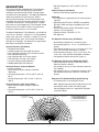
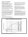
detectors. The detectors have a conical field-of-vision as
shown earlier in Figure 1. The type of fuel and the size
of the fire will determine the range of detection. Aim the
detector at a point equal to, or below horizontal, so that
water, dust and dirt will not accumulate on the optical
surfaces of the detector. As a general rule, mount the
detector so that it will view the base of the area to be
protected.
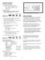
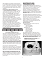
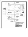
(FIG 4) WIRING DIAGRAM
ELECTRONICS
User Selectable Factory Settings
The electronic module has been factory configured to
provide the user with the following:
Time Delay:
Sensitivity:
5. Complete the installation by wiring the detector
according to wiring diagram (Figure 4). Before assembling
the detector housing to the base, verify that the terminal
block assembly is plugged in all the way and is located at
the top. Insure that the wires are arranged so as not to
interfere with the main electronics module. If a Torque
wrench is available, it is recommended that the four
cap screws be tightened to a value of 35 to 40 in-lbs.
(3.95 to 4.52 NM).
(660/860) 3 Seconds (fire),
(860) 35 Seconds (UV or IR warning)
(860) Fire Event Analysis Level I,
Industrial.
(660) Level 2, Normal
Relays:
Fire
Fault
Normally Open, Latching.
Normally Open, (Relay is failsafe, it
closes upon application of power to
detector), non-latching (cleared after
successful test).
Optical Self-Test:
Automatic (Only Self-Test
Models)
0 to 20 mA
(660-0XXXX/860-XXXXX) “OFF”
Note: The electronics module contains no re-useable
parts. It should never be removed from the housing
assembly. This will result in the voiding of the warranty.
RS485 (660/860) “OFF” — HI-Z mode
-4-