1
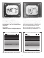
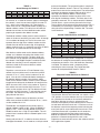
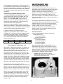
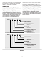
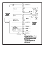
Note: Any adjustments to the user options listed above
should be done with the power “OFF”. The detectors will
not recognize any changes until the microprocessor is
reset. Removing the power does this.
Caution: Upon applying power, insure that the detector
remains on for at least 5 seconds to allow for complete
initialization to take place.
Fire Outputs Latching or Non-Latching
— Models 860 and 660, switch position 6 selects the
latching or non-latching Fire Outputs option. To select
latching, the switch position 6 must be toggled “ON”.
The Fire Outputs signal will remain engaged as long as
power remains “ON” or until the detector is reset through
the RS485 User Interface (UI). If you select non-latching
by toggling switch position 6 to “OFF”, then the Fire
Outputs signal will disengage after a fire is extinguished.
Optical Self-Test
— Models 660-XX1XX and 860-XX1XX: These models
have a “through-the-lens” optical clarity-checking
feature. The factory setting is for automatic test only,
switch position 1 is “OFF”, and switch position 2 is “ON”.
(See Figure 5 and 6 for location of the switches and
Figures 7,8 and 9 that describe the switch settings for
the user selectable interface.) If the addition of the
manual test feature is desired, then toggle the switch
position 1 to “ON”. If only the manual test feature is
needed, then toggle the switch position 1 “ON” and
switch position 2 “OFF”. If no optical testing is preferred,
then ensure that both of these switches are “OFF”.
Models 660-XX0XX and 860-XX0XX do not have either
the manual or the automatic test feature and do not test
the lens for optical clarity. Switch positions 1 and 2 are
non-applicable (N/A) in these detectors.
0 to 20 mA Output
— Models 660-0XXXX and 860-XXXXX switch position
7 selects the 0 to 20 mA output option. If this output is
utilized, then switch position 7 must be “ON” to engage
the peripheral. Otherwise, if this output is not used,
switch position 7 must be kept “OFF” or it will cause the
Fault Outputs to turn “ON”. Table 2 illustrates the order
of priority. For the Model 660-0XXXX, priority 2 is N/A.
TABLE 2 - Milliamp Logic Chart
Priority
State
Load Current mA
1
FIRE
20
2
UV-IR
16
3
FAULT
0
4
NORMAL
4
RS485 User Interface (UI)
The Series 660 and 860 Flame Detectors are equipped
with a two wire, half-duplex, serial communication
interface, which is called the “User Interface” (UI). The
RS485 UI will allow up to 31 detectors to be networked
to a controller (i.e., customized fire panel or personal
computer). The controller will perform the buss arbiter
duties, because the network is in half-duplex mode. This
means that only one transmitter is allowed on the
network at one time.
Activating The RS485 Option
On models 660-0XXXX and 860-XXXXX, switch
position 8 enables this option when it is toggled to the
“ON” position. It becomes disabled in the “OFF” position.
For model 660-1XXXX, switch position 7 performs this
task. This option provides the user with a half-duplex
serial communication network interface for up to 31
detectors.
The RS485 UI has two methods for configuring the
network. For either method, the unit has to be
programmed to a detector number from 01 through 31.
The detector number will give the Flame Detector an
address on the network. For the first method, the RS485
UI option is “ON”. If any alarm state changes, the
detector will send out an “Enquiry Interrupt” (EI). The EI
is the ASCII character “ENQ”, which is equal to the
number 5. Once a fire detector starts to transmit the EI
on the network, it will lock out any other detector from
sending out the EI. The detector will continue to transmit
the EI every second until the buss arbiter has requested
a status from it. For the second method, when the
RS485 UI option is “OFF”, the detector will be inhibited
from sending the EI. The network is still active, but the
detectors will only transmit information or perform a
function when the buss arbiter interrogates them. For
both methods, the detector will wait for a minimum of 16
ms before it will send a response to the buss arbiter.
This delay time allows for the buss arbiter to release the
network from its transmit mode.
NOTE: To determine the proper configuration of the RS485
UI refer to the firmware revision block on the nameplate,
which is a stamped pad located to the right of the model
name. The pad will contain a letter character to indicate
the firmware revision level.
The detector provides the RS485 UI with a “Status
Message”. After a status request is made, the detector
will send out for revision “A” a one-byte word that
represents the Status Message and starting with revision
“B” a six-byte response packet which the fourth byte
contains the status message. As shown in Table 3, the
status message has seven alarm bits and one valid
transmission bit. When bits 0 through 6 are at logic zero,
the alarms are “OFF”. When bits 0 through 6 are at logic
one, the alarms are “ON”. Bit 7 is always “ON”. For
revision “A”, it allows for error checking during
transmission. If a transmission occurs and bit 7 is not set,
then the trans-mission is not valid. Starting with revision
“B”, if bits 4 through 7 are set to logic one then the relay
coil is open. If bit 3 through 7 are set to logic one then the
non-volatile memory has been corrupted.
-7-