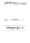
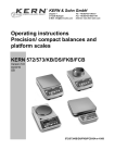
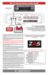
1
KERN & Sohn GmbH
D-72322 Balingen-Frommern
Postbox 4052
E-Mail: [email protected]
E
Service Manual
Electronic Precision Balances
KERN HUM
Version 1.0
- 1 - HUM-SH-e-0210
Tel: 0049-[0]7433- 9933-0
Fax: 0049-[0]7433-9933-149
Internet: www.kern-sohn.de
Page 2
E
KERN HUM
Version 1.0
Service Manual
Electronic Precision Balances
Table of Content
1. INTRODUCTION …………………………………………………………. 3
2. SPECIFICATION ………………………………………………………….
2.1 System Block Diagram ……………………………………………...
2.2 Physical Layout of Electrical Connection ………………………….
2.3 General Specification ………………………………………………..
2.3.1 Overall View ………………………………………………..
2.3.2 Dimensions …………………………………………………
2.3.3 Model Specification ………………………………………..
2.3.4 Operating Conditions ………………………………………
2.3.5 Main Components …………………………………………
2.3.6 Analog Specification ……………………………………….
2.3.7 Capacity & Division ………….……………………………..
4
4
5
6
6
7
7
7
8
8
8
3. INITIAL SETUP ……………………………………………………………. 9
3.1 Internal Functions and Alternate Division …………………………. 9
3.2 Auto and Dealer Calibration ………………………………………… 10
3.3 Disable Calibration with Dip Switch (S1) ………………………….. 10
3.4 Offset and Span Value Data ……………………………………….. 11
3.5 Flow Chart ……………………………………………………………. 12
3.5.1 Auto Calibration (for end-user) ……………………………. 12
3.5.2 Function Test (for technicians only) ………………………. 13
4. TROUBLE SHOOTING ……………………………………………………
4.1 Trouble Shooting Loop ……………………………………………….
4.2 Parts and Components Trouble Shooting ………………………….
4.2.1 Power Supply Check ……………………………………….
4.2.1.1 Relevant Parts …………………………………..
4.2.1.2 Input Voltage: 5.5V or higher …………………..
4.2.1.3 Output Voltage of Regulation: 5V +/- 10% ……
4.2.2 Load Receptor Check ……………………………………….
4.2.3 LCD Display Check ………………………………………….
4.2.4 CPU Check ……………………………………………………
4.2.5 A/D Unit Checking …………………………………………….
17
17
18
18
18
19
19
19
19
19
20
5. ELECTRICAL CIRCUITRY ………………………………………………… 21
5.1 Schematics ……………………………………………………………... 21
5.2 PCB Layout ……………………………………………………………... 26
- 2 - HUM-SH-e-0210
1. INTRODUCTION
Features of the KERN HUM series:
•
•
•
•
•
•
•
•
•
•
•
•
•
•
Full Tare
Tare indicator
Zero indicator
Negative value indicator
Special hold function
2 types of calibration
Dip switch to prevent end-user calibration
Built-in rechargeable battery operated
Operating time after fully charged: 80 hrs.
Low-battery signal
AC adaptor included
LED display – Easy to read
Optional Wireless Remote Controller
Capacity: 1ton, 3ton, 5ton, 7.5ton
- 3 - HUM-SH-e-0210
2. SPECIFICATION
1. SYSTEM BLOCK DIAGRAM
Description: When a load is applied to the loadcell, the resistance to the excitation
current in the strain gauge changes and the analog output signal varies. It is
amplified and digitalized continuously by the A/D converter into a digital signal.
Subsequently, the resulting count is processed and managed by the CPU. The CPU
refers to the instructions from the keyboard and then conveys the output data to the
LCD driver which formats the data into a readout for the display.
- 4 - HUM-SH-e-0210
2. PHYSICAL LAYOUT OF ELECTRICAL CONNECTION
- 5 - HUM-SH-e-0210
3. GENERAL SPECIFICATION
3.1 Overall View
500kg~2ton
3ton
- 6 - HUM-SH-e-0210
5ton, 7.5ton
3.2 Dimension
*Overall Size: 228(D) x 210 (W) x 575(H)mm ---------500kg~2ton capacities
228(D) x 210 (W) x 609(H)mm ---------3ton capacity
228(D) x 210 (W) x 880(H)mm ---------5ton, 7.5ton capacities
3.3 Model Specification
Display resolution : 1/2000(1ton)
1/2500(5ton, 7.5ton)
1/3000(3ton)
Internal resolution: 1/30000
Display: Single-sided
Weight display Æ 5 digits
3.4 Operation condition
* Power source: Rechargeable battery (6V 10 Ah) or AC adapter
(DC 15V, 500mA)
* Operating Temperature: 0°C ~ 40°C
* Operating Humidity : 15 ~ 85% RH
* Power Consumption: 1W/0.1W
5W When charge
- 7 - HUM-SH-e-0210
3.5 Main Components used
* Micro Processor
* Crystal Oscillator
* Display Device
* Loadcell
: 89C51/80C31
: 6 MHz/7.3728MHz
: 7 Segments LED display/Liquid Crystal Display(LCD)
: 350 resistance loadcell
3.6 Analog Specification
* INPUT SENSIVITY
: 2mV/V
* ZERO ADJUST RANGE
: 2% R.O.
* ZERO BALANCE RANGE
: +/-5% R.O.
* L/C APPLIED VOLTAGE
: DC 5V
* SPEED OF A/D CONVERSION : 4 times/sec
* INTERNAL RESOLUTION
: 30000
3.7 Capacity & division
MODEL NO.
HUM1000K500
HUM3000K1000
HUM5000K2000
HUM7500K5000
CAPACITY
1000kg
3000kg
5000kg
7500kg
- 8 - HUM-SH-e-0210
EXTERNAL DIVISION
0.5kg
1kg
2kg
5kg
3. INITIAL SETUP
1. INTERNAL FUNCTIONS AND ALTERNATE DIVISION
INTERNAL FUNCTION TABLE
Function
Symbol
1
F.1
2
F.2
3
F.3
4
F.4
Description
Span value reading and dealer calibration
Full display segment and max. capacity check
Check offset value and scale configuration
Auto power off setting
HOW TO ENTER THE REQUIRED FUNCTION MODE
a. Turn scale off.
b. Press and hold TARE, then turn scale on. Scale display F.1
c. Press TARE until the required function number appears.
d. Press MODE
e. Press MODE until the required setting appears.
f. Press TARE to confirm.
g. Repeat step c to f for other function setting, or
h. Press ZERO to save settings and return to normal operation.
F.1 Span Value Reading and Dealer Calibration
Simply enter F.1, then put on the designated mass to check
Span Value or keep going to do Dealer Calibration.
F.2 Display Segment and Rated Capacity & Division Check
When function is entered, scales will first display the rated capacity and
division, then display all segment. Check and make sure that no segment are
missed.
F.3 Check Offset Value is within acceptable range and Scale Configuration
1. Enter F.3, scale displays the Offset value.
2. Hold MODE (for about 2 seconds)
3. Scale displays capacity and division configuration.
4. Press MODE until the required configuration obtained.
Note: In some countries, only the metric weight unit is available.
5. Press ZERO to save setting and back to normal operation status.
F.4 Auto Power Off Setting
Two modes are available: (Default = 4_OFF)
0._OFF = Auto Power Off function is disabled.
4._OFF = Scale will automatically turned off after 4 minutes unused.
- 9 - HUM-SH-e-0210
2. AUTO AND DEALER CALIBRATION
ACCEPTABLE FOR AUTO AND DEALER CONFIGURATION
Model Number
HUM1000K500
HUM3000K1000
HUM5000K2000
HUM7500K5000
External
Division
1/2000
1/3000
1/2500
1/2500
Acceptable Auto and Dealer Calibration
Load
500kg
1000kg
1000kg
2000kg
2000kg
5000kg
2000kg
5000kg
Dealer Calibration Procedure
1.
2.
3.
4.
5.
6.
7.
8.
9.
10.
11.
12.
13.
14.
15.
Turn scale off.
Press and hold TARE, then turn scale on.
Scale displays F.1
Press MODE
Scale displays offset value
Press ZERO to zero offset value
Press TARE
Press ZERO
Press TARE
Press ZERO, the LED bellows ZERO indicator will be lighted.
It means the scale is ready for dealer calibration.
Make sure that the figure being displayed is =0 or 1, if not, press ZERO
again.
Load calibration either load as listed on above table.
When value display is stable, press MODE.
Wait until the scale start count down.
Calibration completed and scale is ready for operation.
Auto Calibration Procedure
1.
2.
3.
4.
5.
6.
7.
8.
Turn scale off
Press and hold MODE, then turn scale on.
Scale displays CAL?
Press MODE
Scale displays LOAD XXXX or XXXX
Load calibration load according to above table.
Wait until the scale display DONE and start count down.
Calibration completed and scale is ready for operation.
3. DISABLE CALIBRATION WITH DIP SW.(S1)
The DIP SW.#1 is used to control calibration. Push this switch to ON position to
disable calibration.
- 10 - HUM-SH-e-0210
4. OFFSET AND SPAN VALUE DATA
OFFSET AND SPAN VALUE DATA TABLE
Model Number
External
Division
Offset
Span Value (Thousand) at
Value
Various Load Applied
(Thousand)
HUM1000K500 1/2000
4~7
10-16 at 500kg, 25~40 at
1000 kg
HUM3000K1000 1/3000
4~7
10~15 at 1000kg, 20~30
at 2000kg
HUM5000K2000 1/2500
4~7
10~16 at 2000kg, 25~40
at 5000kg
HUM7500K5000 1/2500
4~7
8~16 at 2000kg, 20~30 at
5000kg, 30~45 at 7500kg
Offset
Span
Control Control(Ohm)
R1A R1B
VR1
40k
x
Trimmer
VR1
43.2K x
Trimmer
VR1
25K
x
Trimmer
VR1
18K
x
Trimmer
READING OFFSET VALUE
1. Turn scale off
2. Remove all load from platter
3. Enter F.3 and read the offset value
READING SPAN VALUE
1. Turn scale off
2. Remove all load from platter
3. Enter F.1
4. Press ZERO
5. Apply load to platter. Span value according to load applied will be
displayed.
HOW TO ADJUST OFFSET VALUE
In case the offset value is out of range, adjust the trimmer located at
VR1(TR2) on the mainboard to obtain correct offset value.
HOW TO ADJUST SPAN VALUE
The span value is controlled by resistor located on R1A and R1B Standard
resistor value of R1A and R1B is listed on the above table.
If the required span value is not attained, then change R1A and/or R1B
resistor according to either case below:
Span value too low : Increase the resistance of R1A and/or R1B.
Span value too high : Decrease the resistance of R1A and/or R1B.
- 11 - HUM-SH-e-0210
5. FLOW CHART
5.1 Auto Calibration (for end-user)
- 12 - HUM-SH-e-0210
5.2 Function Test (for technicians only)
- 13 - HUM-SH-e-0210
- 14 - HUM-SH-e-0210
- 15 - HUM-SH-e-0210
- 16 - HUM-SH-e-0210
4. TROUBLE SHOOTING
1. TROUBLE SHOOTING LOOP
- 17 - HUM-SH-e-0210
2. PARTS AND COMPONENTS TROUBLE SHOOTING
2.1 Power Supply Checking
2.11 Relevant parts:
HUM SERIES
Power Board(NCS-20-1)
Q1(C1061)
R1 (1.2 ohm, 1/2W)
Q2 (C945)
DC-JACK (SCD-21)
B1 (W041A)
Main Board(NCS-11-2)
U8 (LM2930-5)
Q2 (A1515)
C30 (EC 10uF/16V)
Q3 (C945)
U9 (HT-7039)
ROCK SW. (R19-00)
- 18 - HUM-SH-e-0210
Description:
1) AC Adaptor: This AC adaptor provides about (15V) dc power.
2) Battery: Built-in Rechargeable Battery (6V 10 Ah).
3) How Battery is charged completely?
The charging voltage is regulated by Q1(C1061) and ZD1(7.5V) for about 7volts.
The charging current will go down automatically If battery’s voltage reached.
Q2(C945) and R1(1.2R,1/2W) provide Over-Current protection.
4) Charging status indications:
LED turns RED(or ORANGE) colour Æ In charged
LED turns GREEN colour Æ Full charged
5) Auto-off:
If the scale is set on 4_Off or even under LO-BAT situation, after some minutes
the CPU will release a negative pulse to cut off Q4 transistor, then Q1 will be cut
off too, therefore the scale is shut down immediately.
6) Low Power Detection:
The U9(HT-7039) is designed to detect the power level. Whenever the power
less than 5.4 V, it will release a low potential signal to CPU, and then CPU will
instruct display to show LO-BAT symbol.
2.1.2 Input voltage: 5.5V or higher
Check and recharge battery if voltage less than 5.5V.
Check and replace DC-Jack or AC adaptor if been defective.
2.1.3 Output voltage of regulation: 5V +/- 10%
Check that the output voltage is within 5V +/- 10%
a) less than 2.7V, the CPU may not work properly.
b) more than 6V, ghost will appear on LCD.
2.2 Load receptor Checking
The load receptor device shall not touch anything around itself during operation.
Check that the load receptor is not contacted with the upper (no load) and/or
lower (with load) stopper.
2.3 LCD Display Checking
2.3.1 Check that it is soldered and connected properly between LCD and driver
IC(uPD/7225) and CPU.
2.3.2 Check whether LCD is broken.
2.4 CPU Checking
2.4.1 Check that all pins are seated properly into the socket.
2.4.2 Check that the Crystal Oscillator works.
2.4.3 Check the RESET is normally low.
- 19 - HUM-SH-e-0210
2.5 A/D Unit Checking
2.5.1 Check that the +5V power is correctly fed to the A/D unit.
2.5.2 Check that the signal output of loadcell is normal.
2.5.3 Check OP.Amplifier & A/D Converter(AD7715).
When no error is found with the above checking procedures, the trouble can be
caused on the loadcell or the PCB itself. Replace a new one could be better to
identify the defective.
In this way, the readout of weight would be varied because of the output voltage of
loadcell and different span value, so recalibration is required after this replacement.
- 20 - HUM-SH-e-0210
5. ELECTRICAL CIRCUITRY
1. SCHEMATICS
HUM series
- 21 - HUM-SH-e-0210
- 22 - HUM-SH-e-0210
- 23 - HUM-SH-e-0210
- 24 - HUM-SH-e-0210
- 25 - HUM-SH-e-0210
2. PCB LAYOUT
- 26 - HUM-SH-e-0210
- 27 - HUM-SH-e-0210
- 28 - HUM-SH-e-0210