1
TECHNICAL MANU
AL
MANUAL
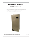
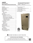
AVPTC Air Handlers
• Refer to Service Manual RS6200006 for installation, operation & troubleshooting information.
• All safety information must be followed as provided in the Service Manual.
• Refer to the appropriate Parts Catalog for part number information.
• Models listed on page 3.
This manual is to be used by qualified, professionally trained HVAC technicians only. Goodman
does not assume any responsibility for property damage or personal injury due to improper
service procedures or services performed by an unqualified person.
Copyright © 2010 - 2011 Goodman Manufacturing Company, L.P.
RT6121001r6
May 2011
PRODUCT IDENTIFICATION
The model number is used for positive identification of component parts used in manufacturing. Please use this number
when requesting service or parts information.
A
V
P
T
C
1830
1
4
EXPANSION
DEVICE:
F: Flowrater
T: TXV
(Expansion
Device)
PRODUCT
TYPE:
A: Air Handler
A
MINOR
REVISION*
MAJOR
REVISION*
CABINET FINISH:
U: Unpainted
P: Painted
N: Uncased
APPLICATION
C: Ceiling Mount PSC Motor
D: Downflow PSC Motor
E: Multi-Position Varible Speed Motor
R: Multi-Position PSC Motor
S: Energy-Efficient Motor:
Multi-Position PSC Motor
T: Coated Coils
V: Variable Speed ECM Motor
A
REFRIGERANT CHARGE:
4:
R-410A
EXPANSION
DEVICE:
C: 4-Wire
Communicating
Ready
ELECTRICAL:
1: 208-230V/1ph/60Hz
NOMINAL CAPACITY RANGE:
Multi-Position & Downflow Applications
1830: 1 1/2 - 2 1/2 Tons
3137: 2 1/2 - 3 Tons
4260: 3 1/2 - 5 Tons
All Airhandlers use DIRECT DRIVE MOTORS. Power supply is AC 208-230v, 60 hz, 1 phase.
WARNING
HIGH VOLTAGE!
Disconnect ALL power before servicing or installing this unit. Multiple power
sources may be present. Failure to do so may cause property damage, personal
injury or death.
Goodman will not be responsible
for any injury or property damage
arising from improper service or service procedures. If
you install or perform service on this unit, you assume
responsibility for any personal injury or property damage
which may result. Many jurisdictions require a license to
install or service heating and air conditioning equipment.
WARNING
2
Installation and repair of this unit
should be performed ONLY by individuals meeting (at a minimum)
the requirements of an "entry level technician", as specified by the Air-Conditioning, Heating, and Refrigeration
Institute (AHRI). Attempting to install or repair this unit
without such background may result in product damage,
personal injury or death.
WARNING
PRODUCT IDENTIFICATION
The model number is used for positive identification of component parts used in manufacturing. Please use this number
when requesting service or parts information.
AVPTC183014**
AVPTC313714**
AVPTC426014**
WARNING
The United States Environmental Protection Agency (“EPA”) has issued various regulations regarding the introduction and disposal of refrigerants introduced into this unit. Failure to follow
these regulations may harm the environment and can lead to the imposition of substantial fines.
These regulations may vary by jurisdiction. Should questions arise, contact your local EPA office.
Do not connect or use any device
that is not design certified by
Goodman for use with this unit.
Serious property damage, personal injury, reduced unit
performance and/or hazardous conditions may result
from the use of such non-approved devices.
WARNING
To prevent the risk of property
damage, personal injury, or death,
do not store combustible materials or use gasoline or
other flammable liquids or vapors in the vicinity of this
appliance.
WARNING
3
PRODUCT DESIGN
WARNING
When installing or servicing this equipment, safety
clothing, including hand and eye protection, is
strongly advised. If installing this equipment in an
area that has special safety requirements (hard hats
etc.), observe these requirements. To protect the
unit when brazing close to the painted surfaces,
the use of a quenching cloth is strongly advised to
prevent scorching or marring of the equipment finish.
AIR HANDLERS
*See Air Handler Specification Sheet for Proper Combinations.
ALL AIR HANDLERS USE DIRECT DRIVE MOTORS. POWER SUPPLY IS 220-240 V, 60 HZ, 1
PHASE
Installation
Before installing this appliance insure that it is properly sized
and adequate power is available.
This appliance can be installed in the vertical position without modification.
The horizontal left and downflow positions require product
modification and instructions for these field conversions can
be found in the AVPTC installation instruction manual.
This product is designed for zero inches (0 inches) clearance; however, adequate access for service or replacement
must be considered without removing permanent structure.
This unit can be installed on a platform when deemed necessary.
WARNING
The unit MUST have an uninterrupted, unbroken
electrical ground to minimize the possibility of personal injury if an electrical fault should occur. The
electrical ground circuit may consist of an appropriately sized electrical wire connecting the
ground lug in the unit control box to the building
electrical service panel. Other methods of grounding are permitted if performed in accordance with
the “National Electric Code” (NEC)/“American National Standards Institute” (ANSI)/“National Fire
Protection Association” (NFPA) 70 and local/state
codes. In Canada, electrical grounding is to be in
accordance with the Canadian Electric Code CSA
C22.1. Failure to observe this warning can result
in electrical shock that can cause personal injury
or death.
WARNING
If this appliance is installed in an enclosed area
such as a garage or utility room with any carbon
monoxide (CO) producing appliance (i.e. automobile, furnace, water-heaters, etc.), ensure the area
is properly ventilated.
4
In an attic installation a secondary drain pan must be provided by the installer and placed under the entire unit with a
separate drain line properly sloped and terminated in an area
visible to the owner. This secondary drain pan is required in
the event that there is a leak or main drain blockage. Closed
cell insulation should be applied to the drain lines in unconditioned spaces where sweating may occur.
Appliances installed in garages, warehouses or other areas
where they may be subjected to mechanical damage must
be suitably guarded against such damage by installing behind protective barriers, being elevated or located out of the
normal path of vehicles. When installed on a base, the base
must also be protected by similar means.
Heating and cooling equipment located in garages, which
may generate a glow, spark or flame capable of igniting flammable vapors, must be installed with the ignition source at
least 18"[46cm] above the floor level.
When more than one appliance is installed in a building it
shall be permanently identified as to the area or space serviced by the equipment.
PRODUCT DESIGN
When this product is installed in the downflow installation in
an unconditioned space, remove the horizontal drain pan and
install the following insulation kit
AVPTC Model
Insulation Kit
1830
DPI36-42/20
3137
4260
See following chart for the correct DPIH kit.
AVPTC Model
Insulation Kit
1830
DPIH36-42
3137
4260
DPIH48-61
DPI48-61/-20
This kit is used to prevent sweating on the vertical drain pan.
To prevent the horizontal drain pan from sweating in high
humidity applications, it is recommended that a DPIH
insulation accessory kit be used. NOTE: The DPIH insulation kit is not supplied with this product and must be
purchased separately.
*AVPTC is a multi-position, variable-speed air handler and is
used with R-410A. The unit's blower design includes a variable-speed ECM motor and is compatible with heat pumps
and variable-capacity cooling applications. (See note below.)
*NOTE: Factory-sealed to achieve a 2% or less leakage rate
at 1.0" water gauge external duct static pressure.
Complies with the Factory-sealed Air Handling Credit as
listed in the 2001 Florida Building Code, Chapter 13, Section
610.2.A.2.1.
5
AVPTC
PRODUCT DIMENSIONS
D
B
C
E
A
SUCTION
LINE
LIQUID
LINE
INLET
TUBE
F
G
I
INLET
(RIGHT SIDE VIEW)
H
INLET
(FRONT VIEW)
Model
A
B
C
D
E
F
G
H
I
J
AVPTC183014
46 3/4"
22"
17 1/2"
19 1/2"
10'
14 1/2"
11 15/16"
17 1/8"
17 15/16"
2"
AVPTC313714
53 1/4"
24"
20"
22"
12"
19 5/8"
11 15/16"
19 5/8"
19 15/16"
1 13/16"
AVPTC426014
53 1/4"
24"
20"
22"
12"
19 5/8"
11 15/16"
19 5/8"
19 15/16"
1 13/16"
6
PRODUCT SPECIFICATIONS
AVPTC
AVPTC183016*
AVPTC313716*
AVPTC426016*
9 1/2"
10 5/8"
10 5/8"
Width
Lineset Connection Size
8"
10 5/8"
10 5/8"
Coil Drain Connection FPT
3/4"
3/4"
3/4"
Liquid
3/8"
3/8"
3/8"
Suction
Electrical Data
Voltage
3/4"
7/8"
7/8"
208/240
208/240
208/240
Min. Circuit Ampacity
4.9/4.9
6.5/6.5
8.6/8.6
15/15
15/15
15/15
197
253
197
253
197
253
FLA
3.90
5.20
6.90
HP
Ship Weight (lbs)
1/2
3/4
1
127
178
197
Blower Wheel
Diameter
Max. Overcurrent Device (amps)
Minimum VAC
Maximum VAC
Blower Motor
7
BLOWER PERFORMANCE DATA
Cooling/Heat Pump Airflow Table
Speed Selection Dip Switches
Adjust
Selection
Switches
Cool
Selection
Switches
Tap
A
B
C
1
OFF
ON
OFF
2
OFF
OFF
ON
D
ON
ON
TRIM
0%
+ 10%
- 10%
0%
Model
3
OFF
ON
OFF
4
OFF
OFF
ON
ON
ON
AVPTC426014*
Pre-Run
Short-Run
Off Delay
5
Electric Heat Airflow Table
6
A
-------
-------
60 sec/100%
OFF
OFF
B
-------
30 sec/50%
60 sec/100%
ON
OFF
7.5 mins/82% 60 sec/100%
OFF
ON
7.5 mins/82%
ON
ON
C
-------
D
30 sec/50%
30 sec/50%
High
Stage
Cool
630
840
1040
610
830
1040
1240
1210
1410
1560
1800
NOTE: Airflow data shown applies to non-communicating mode operation only. For a fully
communicating system, please see the outdoor unit's installation instructions for cooling and heat
pump airflow data. See ComfortNet™ System - Airflow Consideration section for details.
TO SET COMFORT MODE:
Select desired Comfort Mode profile (see profiles above). Set switches
5 and 6 to the appropriate ON/OFF positions.
Profile
Selection
Switches
Profiles
A
B
C
A
B
C
D
A
B
C
D
AVPTC183014*
AVPTC313714*
TO SET AIRFLOW:
1.Select appropriate model from Cooling/Heat Pump Airflow Table.
Based on desired Airflow for your application select corresponding tap
(A,B,C or D). Set dip switches 1 & 2 to the appropriate ON/OFF
positions.
2. Select appropriate Airflow adjustment factor for application
(0%. +10%, -10%). Set dip switches 3 & 4 to the appropriate ON/OFF
positions.
3. If installed with Heater Kit:
Using Electric Heat Airflow Table, set dip switches 9, 10 and 11 to the
appropriate ON/OFF positions based on Heater kit installed.
If installed without Heater Kit:
Ensure dip switches 9, 10 and 11 are set to a valid heater kit selection.
Example: The only valid heater kits for AVPTC183014* applications
are 3, 5, 6, 8 and 10 kW.
Failure to do so will result in a Heater Kit error code.
Low
Stage
Cool
420
560
700
410
560
700
830
810
940
1050
1210
Tap
ON
OFF
ON
AVPTC
183014*
630
730
840
AVPTC
313714*
610
710
840
AVPTC
426014*
600
680
790
OFF
ON
OFF
ON
1080
1270
1060
1260
990
1190
OFF
OFF
ON
OFF
OFF
ON
NR
NR
1470
NR
1390
1580
OFF
OFF
OFF
NR
NR
1580
Htr kW
9
10
11
3
5
6
ON
ON
ON
ON
ON
OFF
8
10
ON
OFF
15
20
21
NOTE: Airflow data shown applies to the emergency heat mode (electric heat only) in either noncommunicating mode operation or fully communicating mode operation.
NOTE: Airflow blink codes are approximations of actual airflow.
Heat Kit Selection
*
MODELS
HKR-03*
HKR-05*/-05C*
HKR-06*
HKR-08*/-08C* HKR-10*/-10C*
HKR-15C
HKR-20C
HKR-21C
AVPTC183014A*
X
X
X
X1
X1
---
---
---
AVPTC313714A*
AVPTC426014A*
X
X
X
X
X
X
X1
X
X1
X
X2
X
--X3
--X3
Revision level that may or may not be designated.
C Circuit breaker option.
NOTE:
When 8kW and 10kW heat kits are used with an AVPTC1830 and AVPTC3137, matched with 2- ton outdoor unit, see Note 1
below.
1
Set Heater Kit dip switches 9, 10 and 11 to 6kW setting (9-ON, 10-OFF,11-ON) to obtain 840 CFM.
2
This heater kit can only be used for ‘1000 CFM or higher’ applications.
3
This heater kit can only be used for ‘1200 CFM or higher’ applications.
8
BLOWER PERFORMANCE DATA
Outdoor
Control
Indoor Control
BIAS Dipswitches
Switch 1 Switch 2
TERM
Dipswitch
TERM
Dipswitches
Switch 3
Switch 1 Switch 2
Data Line
Voltages, Vdc
1-C
2-C
1-2
ON
ON
ON
ON
ON
>2.5
<2.5
>0.2
ON
ON
ON
ON
OFF
ON
ON
OFF
ON
ON
>2.8
>2.8
<2.2
<2.2
>0.6
>0.6
ON
ON
ON
ON
OFF
>2.8
<2.2
>0.6
ON
ON
OFF
OFF
OFF
5
0
5
OFF
ON
ON
ON
ON
0
0
0
ON
OFF
ON
ON
ON
5
5
0
ON or
ON or
OFF
OFF
ON or OFF
0
0
0
OFF
OFF
TERM1 / TERM2 = Termination dipswitches at outdoor unit. See installation
TM
instructions with CT compatiable outdoor unit.
OFF
ON
1
BIAS
2
BIAS
3
TERM
Indoor Unit BIAS and TERMINATION Dipswitches
9
WIRING DIAGRAMS
AVPTC
HIGH VOLTAGE!
DISCONNECT ALL POWER BEFORE SERVICING OR INSTALLING THIS
UNIT. MULTIPLE POWER SOURCES MAY BE PRESENT. FAILURE TO
DO SO MAY CAUSE PROPERTY DAMAGE, PERSONAL INJURY OR DEATH.
FL
FL
FL
FL
HTR1 TL
FL
RD
BK
BK
FL
HTR1 TL
BK
HTR1 TL
BK
HTR2 TL
RD
FL
HTR2 TL
FL
HTR1 TL
HTR2 TL
FL
RD
HTR3 TL
FL
1
BK
BK
2
HTR3 TL
1
BK
YL
HTR4 TL
1
BL
BK
RD
PU
BK
2
3
YL
PU
4
M1
BK
R
5
M2
M1
M1
M3
4
M2
M4
5
RD
M3
M2
6
BK
BR
5
8
YL
M1
M3
M2
M4
BK
RD
WH
M5
M7
M6
M8
R1
BK
6
R2
BK
RD
BK
6
RD
RD
BL
4
BR
5
WH
6
7
BK
RD
4
RD
R2
3
BL
BL
M2
R1
WH
7
BK
BK RD
RD
M1
M4
2
PU
BL
3
BL
R
WH
PU
BK
3
BL
RD
1
2
YL
RD
RD
BL
7
BK
7
YL
8
RD
BK
8
9
YL
RD
9
BL
BK
8
RD
9
9
L1
COLOR CODES:
PK PINK
BR BROWN
WH WHITE
BL BLUE
GY GRAY
RD RED
YL YELLOW
OR ORANGE
PU PURPLE
GN GREEN
BK BLACK
L2
L2
L1
ONE (1) ELEMENT ROWS
L1
TWO (2) ELEMENT ROWS
L2
L1
L2
THREE (3) ELEMENT ROWS
L1 L2
L1 L2
FOUR (4) ELEMENT ROWS
EX
NOTE: WHEN INSTALLING HEATER KIT, ENSURE SPEED TAP DOES NOT EXCEED
MINIMUM BLOWER SPEED (MBS) SPECIFIED FOR THE AIRHANDLER/HEATER
KIT COMBINATION ON THIS UNIT'S S&R PLATE. AFTER INSTALLING OPTION AL HEAT KIT, MARK AN "X" IN THE
LOW VOLTAGE (24V)
LOW VOLTAGE FIELD
PROVIDED ABOVE.
HI VOLTAGE (230V)
MARK ACCORDING TO NUMBER OF HEATER ELEMENT ROWS IN STALLED. NO MARK INDICATES NO HEAT KIT INSTALLED.
HI VOLTAGE FIELD
JUNCTION
L1
TERMINAL
INTERNAL TO
INTEGRATED CONTROL
L2
PL1 PL2
2
3
3
1
1
6
6
5
4
RD
BK
BL
RD
1
3
BL
OVERCURRENT
PROT. DEVICE
PLUG CONNECTION
TR
TH
INDOOR
AIR
CIRCULATOR
BLWR
COM
SEE
NOTE
BK 7
FUSE
CFM LED
DELAY
DEHUM
UNUSED
2
O
Y2
DIP SWITCHES
W2
BIAS
BIAS
TERM
W1
4
LEARN
STATUS
LED
G
RX LED
C
R
SEE NOTE 6
2
1
BL
GY
BK
RD
2
3
4
CIRCULATOR BLOWER
1
ECM MOTOR
HARNESS
GND
1
2
3
4
5
FUSE 3 A
24 VAC
W1 (1)
W1
W2 (2)
W2
Y1
Y2
L2
40 VA
TRANSFORMER
TH
R
24V THERMOSTAT CONNECTIONS
Y1
3
208/230 VAC
L1
DEHUM
24 V THERMOSTAT CONNECTIONS
1
NOTES:
1. PLACE RED WIRES ON TRANSFORMER
TERMINAL 2 FOR 208 VAC OPERATION.
GND
24 V
3A
SEE
NOTE 5
DIAGNOSTIC
LED
COOL
RD
FIELD SPLICE
RESISTOR
BR
ADJUST
9
7
8
9
FIELD GND
DISCONNECT
BL
WH
2
7
8
EQUIPMENT GND
GN
1
BK
GND
GND
2
4
5
4
RD
3
RD
ELEC
HEAT
AF
2
HEAT SEQUENCER R1
+VDC (1)
TO
MICRO
G
RX (2)
TX (3)
INDOOR
AIR
CIRCULATOR
BLWR
O
RD
C
7. DISCARD CONNECTOR PL1 WHEN
INSTALLING OPTIONAL HEAT KIT.
COM
INTEGRATED CONTROL MODULE
5. TO RECALL THE LAST 6 FAULTS, MOST
RECENT TO LEAST RECENT, DEPRESS
SWITCH FOR MORE THAN 2 SECONDS
WHILE IN STANDBY (N THERMOSTAT
INPUTS)
6. BIAS AND TERM DIP SWITCHES MUST BE
IN "ON" POSITION. RED STATUS LED
PROVIDES NETWORK STATUS. GREEN RX
LED INDICATES NETWORK TRAFFIC. USE
LEARN BUTTON TO RESET NETWORK.
DEHUM
TR
BK
3. IF ANY OF THE ORIGINAL WIRES AS
SUPPLIED WITH THIS UNIT MUST
BE REPLACED, IT MUST BE REPLACED
WITH WIRING MATERIAL HAVING A
TEMPERATURE RATING OF AT LEAST 105°C.
USE COPPER CONDUCTORS ONLY.
4. UNIT MUST BE PERMANENTLY
GROUNDED AND CONFORM TO N.E.C AND
LOCAL CODES.
HEAT SEQUENCER R2
GND (4)
GN
2. MANUFACTURER'S SPECIFIED
REPLACEMENT PARTS MUST BE USED
WHEN SERVICING.
GND
0140A00039-D
Wiring is subject to change. Always refer to the wiring diagram on the unit for the most up-to-date wiring.
10