1
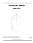
TECHNICAL MANU
AL
MANUAL
MBVC Blowers
• Refer to Service Manual RS6200007 for installation, operation, and troubleshooting information.
• All safety information must be followed as provided in the Service Manual.
• Refer to the appropriate Parts Catalog for part number information.
• Models listed on page 2.
This manual is to be used by qualified, professionally trained HVAC technicians only. Goodman
does not assume any responsibility for property damage or personal injury due to improper
service procedures or services performed by an unqualified person.
Copyright © 2009 - 2011 Goodman Manufacturing Company, L.P.
RT6223003r1
January 2011
PRODUCT IDENTIFICATION
The model number is used for positive identification of component parts used in manufacturing. Please use this number
when requesting service or parts information.
MBVC1200AA-1**
MBVC1600AA-1**
MBVC2000AA-1**
MB
V
C
12
DESIGN SERIES:
MB: Modular Blower
00
FACTORY HEAT:
00: No Heat
COMMUNICATION
FEATURE:
C: 4-wire
Communication
Ready
MOTOR TYPE:
V: Variable Speed
WARNING
A
1
DESIGN SERIES:
A: First Series
CIRCUIT BREAKER:
A: No Circuit Breaker
B: Circuit Breaker
ELECTRICAL SUPPLY:
1: 208-230V/60HZ/1 phase
AIRLOW DELIVERED:
12: 1200 CFM
16: 1600 CFM
20: 2000 CFM
HIGH VOLTAGE!
Disconnect ALL power before servicing or installing this unit. Multiple power
sources may be present. Failure to do so may cause property damage, personal
injury or death.
Goodman will not be responsible
for any injury or property damage
arising from improper service or service procedures. If
you install or perform service on this unit, you assume
responsibility for any personal injury or property damage
which may result. Many jurisdictions require a license to
install or service heating and air conditioning equipment.
WARNING
Installation and repair of this unit
should be performed ONLY by
individuals meeting (at a minimum) the requirements of
an "entry level technician" as specified by the Air-Conditioning, Heating, and Refrigeration Institute (AHRI). Attempting to install or repair this unit without such background may result in product damage, personal injury or
death.
WARNING
The United States Environmental Protection Agency (“EPA”) has issued various regulations regarding the introduction and disposal of refrigerants introduced into this unit. Failure to follow
these regulations may harm the environment and can lead to the imposition of substantial fines.
These regulations may vary by jurisdiction. Should questions arise, contact your local EPA office.
Do not connect or use any device
that is not design certified by
Goodman for use with this unit.
Serious property damage, personal injury, reduced unit
performance and/or hazardous conditions may result
from the use of such non-approved devices.
WARNING
2
A
WARNING
To prevent the risk of property
damage, personal injury, or death,
do not store combustible materials or use gasoline or
other flammable liquids or vapors in the vicinity of this
appliance.
WARNING
PRODUCT DESIGN
GENERAL INFORMATION
The MBVC Blower Cabinets are used in combination with a
cased evaporator coil for a two-piece blower and coil combination. This combination of blower and coil functions as the
indoor part of a split air-conditioning system, and may be
matched with a remote condensing or heat pump unit and
allows for a variety of mix-matching possibilities.
The blower cabinet can also function as an electric furnace
when used with an electric heater.
NOTE: The electric heating elements for electric furnace
installation are not shipped with the cabinet and are fieldinstalled. Electric heater kits (HKR) are available as sales
accessories for supplemental electric heat.
Systems should be properly sized by heat gain and loss
calculations made according to methods of the Air Conditioning Contractors Association (ACCA) or equivalent. It is
the contractor’s responsibility to ensure the system has adequate capacity to heat or cool the conditioned space.
The MBVC blower cabinet uses a variable speed motor that
maintains a constant airflow with a higher duct static. It is
approved for applications with cooling coils of up to 0.8 inches
W.C. external static pressure and includes a feature that
allows airflow to be changed to + 10%.
The MBVC blower cabinets, with proper coil matches, can
be positioned for upflow, counterflow, horizontal right or horizontal left operation. All units are constructed with R-4.2
insulation. In areas of extreme humidity (greater than 80%
consistently), insulate the exterior of the blower with insulation having a vapor barrier equivalent to ductwork insulation,
providing local codes permit.
The CAPX/CHPX coils are equipped with a thermostatic expansion valve that has a built-in internal check valve for refrigerant metering. The CACF/CAPF/CHPF coils are equipped
with a fixed restrictor orifice.
The coils are designed for upflow, counterflow, or horizontal
application, using ECM motors on the MBVC models.
FEATURES
This modular blower is a part of the ComfortNet™ family of
products. It may be installed as part of a “legacy” system
using a standard 24 VAC thermostat. However, with the
CTK01AA ComfortNet thermostat kit, this modular blower may
be installed as part of a digitally communicating system. The
ComfortNet system provides automatic airflow configuration,
enhanced setup features, and enhanced diagnostics. It also
reduces the number of thermostat wires to a maximum of
four.
COMFORTNET SYSTEM
OVERVIEW
The ComfortNet system (or CT system) is a system that
includes a ComfortNet compatible modular blower and air
conditioner or heat pump with a CTK01AA thermostat. Any
other system configurations are considered invalid ComfortNet
systems and must be connected as a traditional (or legacy)
system. The table below compares the valid CT systems.
CT compatible
Modular Blower
CT compatible
Air Conditioner
Full CT system
benefits & features
CT compatible
Modular Blower
CT compatible
Heat Pump
Full CT system
benefits & features
A ComfortNe™ heating/air conditioning system differs from a
legacy/traditional system in the manner in which the indoor
unit, outdoor unit and thermostat interact with one another.
In a traditional system, the thermostat sends commands to
the indoor and outdoor units via analog 24 VAC signals. It is
a one-way communication path in that the indoor and outdoor units typically do not return information to the thermostat.
On the other hand, the indoor unit, outdoor unit, and thermostat comprising a ComfortNet system “communicate” digitally with one another. It is now a two-way communications
path. The thermostat still sends commands to the indoor
and outdoor units. However, the thermostat may also request and receive information from both the indoor and outdoor units. This information may be displayed on the CT
thermostat. The indoor and outdoor units also interact with
one another. The outdoor unit may send commands to or
request information from the indoor unit. This two-way digital
communications between the thermostat and subsystems
(indoor/outdoor unit) and between subsystems is the key to
unlocking the benefits and features of the ComfortNet system.
Two-way digital communications is accomplished using only
two wires. The thermostat and subsystem controls are powered with 24 VAC Thus, a maximum of 4 wires between the
equipment and thermostat is all that is required to operate
the system.
3
MBVC BLOWER SPECIFICATIONS
D
3 1/4
5 C1/8
(3) KNOCKOUTS
1.125
1.375
1.750
.875 KNOCKOUT
(2 PLACES)
H
5
6 1/2
W
MBVC1200/1600/2000
Dimensions, inches (mm)
Physical Information
Blower Wheel
(D x W)
Blower Motor
(HP)
MCA1
MOP1
W
H
D
Shipping
Weight
lbs.(kg)
MBVC1200
10X8
1/2
4.3
15
17½
(445)
26
(660)
21
(533)
72
(32.6)
MBVC1600
10X8
3/4
6.3
15
21
(533)
30
(762)
21
(533)
82
(37.2)
MBVC2000
11X10
3/4
5.8
15
24½
(622)
30
(762)
21
(533)
94
(42.6)
MODEL
1
4
Minimum Circuit Ampacity (MCA) and Maximum Overcurrent Protection (MOP) for blower without supplemental heat
installed. Refer to unit nameplate for MCA and MOP with approved accessory heaters installed.
MBVC BLOWER SPECIFICATIONS
BLOWER OPENING DIMENSIONS
(TOP VIEW)
10-7/8”
11”
10-1/4”
13-1/4”
11-5/16”
11-5/16”
20-1/16”
16-1/2”
23-1/2”
SMALL
LARGE
MEDIUM
MBVC1200/1600/2000
HKR HEATER DATA
HEATER KIT
BLOWER
NO HEAT KIT
HKR-03*
HKR05-(C)*
HKR-06*
HKR-08(C)*
1200AA-1**
X
X
X
X
X
1600AA-1**
X
X
X
X
X
2000AA-1**
X
X
X
X
X
MBVC
^ = Circuit 1: Single Phase for Air Handler Motor
Circuit 2: 3-Phase for HKR3 Heater Kits
* = Revision level that my or may not be designated
C = Circuit Breaker option
X = Allowable combinations
~ = Restricted combinations
HEATER KIT
BLOWER
HKR-10(C)*
HKR-15C*
HKR-20C*
HKR-21C*
1200AA-1**
X
X
~
~
1600AA-1**
X
X
~
~
2000AA-1**
X
X
X
~
MBVC
^ = Circuit 1: Single Phase for Air Handler Motor
Circuit 2: 3-Phase for HKR3 Heater Kits
* = Revision level that my or may not be designated
C = Circuit Breaker option
X = Allowable combinations
~ = Restricted combinations
5
BLOWER PERFORMANCE DATA
SWITCH
9
SWITCH
10
SWITCH
11
800
800
ON
ON
ON
ON
ON
OFF
800
ON
OFF
ON
OFF
HTR kW
MBVC1200*
MBVC1600*
MBVC2000*
3
5
600
600
800
800
6
635
800
8
740
1000
1000
ON
OFF
10
1000
1000
1200
OFF
ON
ON
15
1400
1500
1500
20
NR
NR
2000
OFF
OFF
ON
OFF
OFF
ON
21
NR
NR
NR
ON^
ON^
ON^
^ Factory setting
MODEL
MBVC1200
MBVC1600
MBVC2000
COOL SELECTION
SWITCHES
ADJUST SELECTION
SWITCHES
LOW STAGE
COOL
HIGH STAGE
COOL
400
540
600
800
1
OFF
ON
2
OFF
670
1000
OFF
ON
ON
OFF
3
OFF
ON
OFF
4
OFF
OFF
ON
PROFILE SELECTION
SWITCHES
5
OFF
ON
ON
ON
OFF
ON
ON
800
1200
ON
1000
OFF
1200
ON
ON
OFF
OFF
OFF
800
OFF
OFF
OFF
ON
OFF
OFF
940
1400
OFF
ON
OFF
ON
OFF
ON
1070
800
1600
1200
ON
OFF
ON
ON
OFF
ON
OFF
ON
OFF
ON
OFF
OFF
1070
1600
ON
OFF
ON
OFF
ON
OFF
1200
1800
OFF
ON
ON
ON
OFF
2000
ON
ON
OFF
1340
ON
ON
ON
Locate the blower speed selection DIP switches on the integrated control module. Select the desired
“cooling” speed tap by positioning switches 1 and 2 appropriately. Select the desired “adjust” tap by
positioning switches 3 and 4 appropriately. Refer to the following figure for switch positions and their
corresponding taps. Verify CFM by counting the number of times the green CFM LED blinks.
Normal*
+10%
OFF ON
OFF ON
-10%
OFF
ON
Normal
OFF
3
3
3
3
4
4
4
4
ON
Air flow Adjust Taps (*indicates factory setting)
Thermostat "Fan Only" Mode
During "Fan Only" operations, the CFM output is 30% of the maximum CFM capability.
CFM Trim Adjust
Minor adjustments can be made through the dipswitch combination of 3-4.
6
OFF
670
ON
ON
6
OFF
WIRING DIAGRAMS
THERMOSTATS
HIGH VOLTAGE!
DISCONNECT ALL POWER BEFORE SERVICING OR INSTALLING THIS
UNIT. MULTIPLE POWER SOURCES MAY BE PRESENT. FAILURE TO
DO SO MAY CAUSE PROPERTY DAMAGE, PERSONAL INJURY OR DEATH.
Typical Two-Stage Cool, Two-Stage Heat
Thermostat
Y2
R
C
Y1
G
W1 W2
1
2
R C G
W1 W2 Y1
Y2
Y1
Y2
O
DEHUM
Modular Blower
Integrated Control Module
*
C
R
NEU
Dehumidistat
[Optional]
HOT
Remote Condensing Unit
(Two-Stage AC)
Typical Two-Stage Cooling with Two-Stage Heating
O
R
C
Y1
G
EMR
1
2
R C G
Typical Two-Stage Cool,
Two-Stage Heat
Heat Pump Thermostat
Y2
W2
W1 W2 Y1
Y2
O
W1
Y2
O
DEHUM
Modular Blower
Integrated Control Module
*
C
R
Y1
NEU
Dehumidistat
[Optional]
HOT
Remote Condensing Unit
(Two-Stage HP)
Typical Two Stage Heat Pump heating and Auxiliary/Emergency Heating
Wiring is subject to change. Always refer to the wiring diagram on the unit for the most up-to-date wiring.
7
WIRING DIAGRAMS
HIGH VOLTAGE!
DISCONNECT ALL POWER BEFORE SERVICING OR INSTALLING THIS
UNIT. MULTIPLE POWER SOURCES MAY BE PRESENT. FAILURE TO
DO SO MAY CAUSE PROPERTY DAMAGE, PERSONAL INJURY OR DEATH.
FL
FL
FL
FL
HTR2 TL
FL
HTR1 TL
RD
BK
BK
BK
FL
HTR1 TL
PLM
H TR1 TL
BK
H TR2 TL
RD
FL
HT R1 TL
FL
HT R2 TL
FL
RD
PLM
1
BK
BK
2
BK
H TR3 TL
FL
P LM
HT R3 TL
1
YL
H TR4 TL
1
PLM
BL
BK
RD
PU
BL
BK
2
3
4
M1
R
RD
5
M2
YL
PU
BL
BK
6
M1
M1
M3
4
M2
M4
5
RD
M2
BK
BL
4
BR
5
M2
R2
RD
WH
RD
3
M1
YL
M3
M5
M7
M6
M8
RD
BL
RD
M2
M4
R1
R2
4
5
BR
BK
6
BK
RD
6
WH
7
7
BK
8
BK R D
BL
6
BK
RD
M1
M4
R1
WH
7
BK
M3
BL
RD
BK
BK
2
PU
3
BL
R
WH
PU
BK
3
1
2
YL
RD
RD
7
YL
8
RD
9
YL
BK
8
RD
BL
BK
9
8
RD
9
9
L1
L2
L1
ONE (1) ELEMENT ROWS
L2
L1
TWO (2) ELEMENT ROWS
L2
L1
L2
THREE (3) ELEMENT ROWS
L1
L2
L1
L2
FOUR (4) ELEMENT ROWS
NOTE: WHEN INSTALLING HEATER KIT, ENSURE SPEED TAP DOES NOT EXCEED MINIMUM BLOWER SPEED (MBS) SPECIFIED FOR THE AIRHANDLER/HEATER
KIT COMBINATION ON THIS UNIT'S S&R PLATE. AFTER INSTALLING OPTIONAL HEAT KIT, MARK AN "X" IN THE
PROVIDED ABOVE.
MARK ACCORDING TO NUMBER OF HEATER ELEMENT ROW S INSTALLED. NO MARK INDICATES NO HEAT KIT INSTALLED.
2
2
230 VAC
RD
3
1
1
208 VAC
24 VAC
GN
DISCONNECT
COM
BK
L2
GND
GND
RD
RD
3
L1
40 VA TRANSFORMER, SEE NOTE 1
PL1 PL2
BL
BK
BR
BL
RD
1
3
BL
TR
TH
4 CIRCUIT HEATER
CONNECTOR
SEE
NOTE
7
FUSE
CFM LED
ELEC
HEAT
AF
DELAY
DEHUM
UNUSED
ADJUST
O
Y2
2
DIP SWITCHES
W2
LEARN
W1
BIAS
TERM
STATUS
LED
BIAS
4
G
C
RX LED
R
SEE NOTE 6
2
1
TWO-STAGE INTEGRATED CONTROL MODULE
BL
GY
BK
RD
3
2
1
ECM MOTOR
HARNESS
TH
24 VAC
W1 (1)
W1
W2 (2)
W2
Y1
Y2
HEAT SEQUENCER R1
HEAT SEQUENCER R2
+VDC (1)
TO
MICRO
G
RX (2)
INDOOR
AIR
CIRCULATOR
BLWR
TX (3)
O
4
CIRCULATOR BLOWER
FUSE 3 A
L2
40 VA
TRANSFORMER
R
24V THERMOSTAT CONNECTIONS
Y1
3
208/230 VAC
L1
DEHUM
24 V THERMOSTAT CONNECTIONS
1
GND
24 V
3A
SEE
NOTE 5
DIAGNOSTIC
LED
COOL
R
D
INDOOR
AIR
CIRCULATOR
BLWR
COM
-
B
K
7
8
9
WH
2
6
5
4
5
4
7
8
9
4
6
GND
1
2
3
4
5
DEHUM
GND (4)
GN
C
TR
BK
COM
RD
INTEGRATED CONTROL MODULE
NOTES:
1. PLACE RED WIRE ON TRANSFORMER TERMINAL 2 FOR 208 VAC
OPERATION.
2. MANUFACTURER'S SPECIFIED REPLACEMENT PARTS MUST BE USED
WHEN SERVICING.
3. IF ANY OF THE ORIGINAL WIRE AS SUPPLIED WITH THE BLOWER MUST
BE REPLACED, IT MUST BE REPLACED WITH WIRING MATERIAL HAVING A
TEMPERATURE RATING OF AT LEAST 105°C. USE COPPER CONDUCTORS
ONLY.
4. UNIT MUST BE PERMANENTLY GROUNDED AND CONFORM TO N.E.C. AND
LOCAL CODES.
5. TO RECALL THE LAST 6 FAULTS, MOST RECENT TO LEAST RECENT,
DEPRESS SWITCH FOR MORE THAN 2 SECONDS WHILE IN STANDBY (N
THERMOSTAT INPUTS).
6. BIAS AND TERM DIPSWITCHES MUST BE IN "ON" POSITION. RED
STATUS LED PROVIDES NETWORK STATUS. GREEN RX LED INDICATES
NETWORK TRAFFIC. USE LEARN BUTTON TO RESET NETWORK.
COLOR CODES:
PK PINK
BR BROWN
WH WHITE
BL BLUE
GY GRAY
RD RED
YL YELLOW
OR ORANGE
VT VIOLET
GN GREEN
BK BLACK
GND
LOW VOLTAGE (24V)
LOW VOLTAGE FIELD
HI VOLTAGE (230V)
HI VOLTAGE FIELD
JUNCTION
TERMINAL
INTERNAL TO
INTEGRATED CONTROL
EQUIPMENT GND
FIELD GND
FIELD SPLICE
RESISTER
7. DISCARD CONNECTOR PL1 WHEN INSTALLING OPTIONAL HEAT KIT.
0140A00039 REV. A
OVERCURRENT
PROT. DEVICE
PLUG CONNECTION
Wiring is subject to change. Always refer to the wiring diagram on the unit for the most up-to-date wiring.
8