1
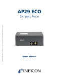
Publication: INFICON - Part number nipb69e1-a (1302) - All information can be modified without prior notice AP29 ECO Sampling Probe Service Manual Contents 1. Introduction . . . . . . . . . . . . . . . . . . . . . . . . . . . . . . . . . . . . . . . . . . . . . . . . . . . . . . . . . .2 2. System Description . . . . . . . . . . . . . . . . . . . . . . . . . . . . . . . . . . . . . . . . . . . . . . . . . . . .3 3. 4. 5. 2.1. General . . . . . . . . . . . . . . . . . . . . . . . . . . . . . . . . . . . . . . . . . . . . . . . . . . . . . . . . . .3 2.2. Hydrogen Gas. . . . . . . . . . . . . . . . . . . . . . . . . . . . . . . . . . . . . . . . . . . . . . . . . . . . .3 2.3. Main Parts . . . . . . . . . . . . . . . . . . . . . . . . . . . . . . . . . . . . . . . . . . . . . . . . . . . . . . .4 2.4. System Setup . . . . . . . . . . . . . . . . . . . . . . . . . . . . . . . . . . . . . . . . . . . . . . . . . . . . .5 Operational Modes . . . . . . . . . . . . . . . . . . . . . . . . . . . . . . . . . . . . . . . . . . . . . . . . . . . . .6 3.1. Reference Gas Calibration Sequence . . . . . . . . . . . . . . . . . . . . . . . . . . . . . . . . . . .6 3.2. Measure Sequence . . . . . . . . . . . . . . . . . . . . . . . . . . . . . . . . . . . . . . . . . . . . . . . . .7 3.3. Sample Calibration Sequence . . . . . . . . . . . . . . . . . . . . . . . . . . . . . . . . . . . . . . . .8 3.4. Gas Flow . . . . . . . . . . . . . . . . . . . . . . . . . . . . . . . . . . . . . . . . . . . . . . . . . . . . . . . .9 Function Test . . . . . . . . . . . . . . . . . . . . . . . . . . . . . . . . . . . . . . . . . . . . . . . . . . . . . . . .19 4.1. Function Test . . . . . . . . . . . . . . . . . . . . . . . . . . . . . . . . . . . . . . . . . . . . . . . . . . . .19 4.2. Operation Test . . . . . . . . . . . . . . . . . . . . . . . . . . . . . . . . . . . . . . . . . . . . . . . . . . .23 4.3. Tightness Control . . . . . . . . . . . . . . . . . . . . . . . . . . . . . . . . . . . . . . . . . . . . . . . . .25 Maintenance and Service . . . . . . . . . . . . . . . . . . . . . . . . . . . . . . . . . . . . . . . . . . . . . . .27 5.1. Changing Sniffer Flow Orifices . . . . . . . . . . . . . . . . . . . . . . . . . . . . . . . . . . . . . .27 5.2. Adjusting Flow Alarm Switches. . . . . . . . . . . . . . . . . . . . . . . . . . . . . . . . . . . . . .29 5.3. Replacing Flow Alarm Switches . . . . . . . . . . . . . . . . . . . . . . . . . . . . . . . . . . . . .31 5.4. Replacing Sample or Purging Pump . . . . . . . . . . . . . . . . . . . . . . . . . . . . . . . . . .31 5.5. Replacing the Valves . . . . . . . . . . . . . . . . . . . . . . . . . . . . . . . . . . . . . . . . . . . . . .32 6. Illustrated Parts Breakdown . . . . . . . . . . . . . . . . . . . . . . . . . . . . . . . . . . . . . . . . . . . . .33 7. Spare Parts . . . . . . . . . . . . . . . . . . . . . . . . . . . . . . . . . . . . . . . . . . . . . . . . . . . . . . . . . .39 8. Electric Diagram . . . . . . . . . . . . . . . . . . . . . . . . . . . . . . . . . . . . . . . . . . . . . . . . . . . . .43 9. Pneumatic Diagram . . . . . . . . . . . . . . . . . . . . . . . . . . . . . . . . . . . . . . . . . . . . . . . . . . .44 10. Technical Data . . . . . . . . . . . . . . . . . . . . . . . . . . . . . . . . . . . . . . . . . . . . . . . . . . . . . . .45 11. Contact Information . . . . . . . . . . . . . . . . . . . . . . . . . . . . . . . . . . . . . . . . . . . . . . . . . . .46 INFICON - Maintenance Manual AP29 ECO 1 1. Introduction Together with Hydrogen Leak Detector Sensistor ISH2000, the Sampling probe AP29 ECO forms a complete, industrial leak-detection unit, to be incorporated into an automatic leak tester. The AP29 ECO is intended for intermittent or continuous sampling of a test point or test chamber. It performs quick and accurate accept/reject testing. Note! The AP29 ECO can only be controlled by Leak Detector Sensistor ISH2000 with software version 3.00 or higher. Upgrade kit can be ordered from your supplier. Typical applications for the AP29 ECO are:· 2 • Integral testing in accumulating test chamber. • Point testing of pipe joints. For example, refrigeration and automotive pipes. • Automatic surface or weld seam scanning. INFICON - Maintenance Manual AP29 ECO 2. System Description 2.1. General The standard configuration has a sniffer flow rate of 3.0 std cc/s which gives a direct sniffing sensitivity better than 3x10⁻⁵ std cc/s (4 g/yr R134). Considerably higher sensitivities can be achieved for point testing applications by using the accumulation technique supported by the Sensistor ISH2000 software. Consult your supplier for best system design for your particular application. The AP29 ECO is equipped with two separate sniffer flow channels: Sampling and Analysing flow. This configuration makes it possible to perform true steady-state measurements. The constant sniffer flows are created by a pump pulling air through two high-precision ruby orifices. A critical flow type situation is obtained. The orifices are protected by built-in filters, see Figure 21 position 5 in Chapter 5. The flow is supervised by two differential flow alarm switches activated by the pressure drop across the orifices. The switches are factory set to open at 75% of the nominal sniffer flow. The AP29 ECO is equipped with an overexposure protection mode purging the sensor with reference air as soon as the signal goes above the rejection threshold. This reduces the recovery time of the sensor enabling the system to work with high speed testing applications. The unit is also equipped with a reference mode. This allows for fast and automatic calibration adjustment, with a certified gas mixture of Hydrogen in Air. An optional software driver can be ordered if calibration with reference leak is preferred. See further in calibration section below. The Sensistor ISH2000 system offers 24 VDC logic signals for valve control, leak alarms, sniffer flow alarm etc. for easy interfacing to any PLC system. The AP29 ECO is designed for minimum maintenance and easiest possible service. 2.2. Hydrogen Gas Hydrogen as a tracer gas for leak detection. When pure hydrogen gas is released in air its flammability region spans from 4% to 75% of hydrogen in air. Below 4% there is not enough chemical energy available for a flame to occur. Above 75% hydrogen there is not enough oxygen left to support a flame. When, for example, a mixture of less than 5.7% hydrogen in nitrogen mixes with air there will never be enough energy to support a flame, irrespective of the ratio of air-to-gas. When a mixture of more than 5.7% hydrogen in nitrogen is released into air there is a region of ratios between air-to-gas where the mixture is flammable. When, for example, a mixture of 10% hydrogen in nitrogen mixes with air there is still very little energy available. Only in very special circumstances can a flame be self-supporting. Such mixtures cannot detonate. Warning! Never use a mixture containing more than 5% hydrogen or make your own mixtures. Otherwise, an explosion can occur which can result in serious injury. INFICON - Maintenance Manual AP29 ECO 3 2.3. Main Parts The AP29 ECO has five main parts: • main valve block • sensor • solenoid valves • flow alarm switch • two pumps. See Figure 1. Figure 1 Main parts. 1 Flow alarm switch 2 Sensor 3 Solenoid valve 4 Pump 5 Main valve block Table 1 Key to Figure 1. 4 INFICON - Maintenance Manual AP29 ECO 2.4. System Setup Typical setup, ILS500 including the Sensistor ISH2000 together with an AP29 ECO and a test fixture. See Figure 2. Figure 2 Typical setup. INFICON - Maintenance Manual AP29 ECO 5 3. Operational Modes 3.1. Reference Gas Calibration Sequence Reference gas calibration sequence is shown in Figure 3. Start No Signal = 0? Yes Purge reference gas hose Expose sensor to reference gas Calibrate sensor Yes Within tolerance? Calibration performed No Calibration rejected Set REJECT output Purge system To Standby Figure 3 Reference gas calibration sequence flow chart. 6 INFICON - Maintenance Manual AP29 ECO 3.2. Measure Sequence Measure sequence is shown in Figure 4. Start Accumulation During D seconds Sampling During B seconds No Yes Analysis During A seconds Leak? Yes > Purge level? Set REJECT output Set REJECT output Purge sensor Purge sensor During C seconds Purge sampling valve Purge sampling valve Purge calibration valve No Set ACCEPT output Purge sensor During C seconds To Standby Figure 4 Measure sequence flow chart. INFICON - Maintenance Manual AP29 ECO 7 3.3. Sample Calibration Sequence Sample calibration sequence is shown in Figure 5. Start No Signal = 0? Yes Accumulation Duration D seconds Sampling Duration B seconds Expose sensor to sampled gas Duration B seconds Calibrate sensor Within tolerance? Yes Calibration performed No Calibration rejected Set REJECT output Purge system To Standby Figure 5 Sample calibration sequence flow chart. 8 INFICON - Maintenance Manual AP29 ECO 3.4. Gas Flow Visual descriptions over the gas flow are presented below. 3.4.1. Stand-by Mode Reference air = Sample = Reference gas = MM 9 %XHAUST 6ACUUM 9 MM 2EF'AS !0%#/##'- 2EF'AS 9 3AMPLE 9 " 9 MM ( !0%#/30- " MM %XHAUST - - - - &RESHAIR Figure 6 Gas flow in Stand-by mode. INFICON - Maintenance Manual AP29 ECO 9 3.4.2. Calibration Reference air = Sample = Reference gas = Step 1 MM !0%#/##'- 9 9 %XHAUST 2EF'AS 6ACUUM MM 2EF'AS 9 3AMPLE 9 " 9 MM ( !0%#/30- " MM %XHAUST - - - - &RESHAIR Figure 7 Gas flow in calibration mode, under 0.3 seconds. Under 0.3 seconds: No Calibration gas (Reference gas). Reference air (Fresh air) flow passes the sensor H65. See Figure 7. This is only valid if you do the calibration through the Reference Gas Port. If you use the Sample Inlet Port to do the calibration instead, then the steps 2 through 4 are not used. 10 INFICON - Maintenance Manual AP29 ECO Step 2 MM !0%#/##'- 9 9 %XHAUST 2EF'AS 6ACUUM MM 2EF'AS 9 3AMPLE 9 " 9 MM ( !0%#/30- " MM %XHAUST - - - - &RESHAIR Figure 8 Calibration gas flow, under 0.5 seconds. Under 0.5 seconds: Calibration gas (Reference gas) flows to the exhaust. Reference air (Fresh air) flows pass the sensors. See Figure 8. INFICON - Maintenance Manual AP29 ECO 11 Step 3 MM 9 %XHAUST 6ACUUM 9 MM 2EF'AS !0%#/##'- 2EF'AS 9 3AMPLE 9 " 9 MM ( !0%#/30- " MM %XHAUST - - - - &RESHAIR Figure 9 Calibration gas flow under the calibration period. Calibration gas (Reference gas) flows to the exhaust and passes the sensor under the calibration period. See Figure 9. 12 INFICON - Maintenance Manual AP29 ECO Step 4 MM !0%#/##'- 9 9 %XHAUST 2EF'AS 6ACUUM MM 2EF'AS 9 3AMPLE 9 " 9 MM ( !0%#/30- " MM %XHAUST - - - - &RESHAIR Figure 10 When calibration passed or failed, 3 seconds. After 3 seconds: When calibration passed or failed Air purging the valve –Y05 and the sensor, see Figure 10. INFICON - Maintenance Manual AP29 ECO 13 Sampling 3.4.3. Reference air = Sample = Reference gas = MM !0%#/##'- 9 9 %XHAUST 2EF'AS 6ACUUM MM 2EF'AS 9 3AMPLE 9 " 9 MM ( !0%#/30- " MM %XHAUST - - - - &RESHAIR Figure 11 After accumulation time. After accumulation time (Timer D), the Valve –Y02 will go from LO to HI mode. The Gas Sample Sniffing goes directly to the exhaust and the sensor is purged with Fresh air under B seconds (Timer B). See Figure 11. 14 INFICON - Maintenance Manual AP29 ECO Analysing Step 1 MM 9 %XHAUST 6ACUUM 9 MM 2EF'AS !0%#/##'- 2EF'AS 9 3AMPLE " 9 9 ( MM " MM !0%#/30- 3.4.4. %XHAUST &RESHAIR Figure 12 Under 0.2 seconds + A seconds (Timer). Under 0.2 seconds + A seconds (Timer) the sample will pass the sensor. See Figure 12. INFICON - Maintenance Manual AP29 ECO 15 Step 2 MM 9 %XHAUST 6ACUUM 9 MM 2EF'AS !0%#/##'- 2EF'AS 9 3AMPLE 9 " 9 MM ( !0%#/30- " MM %XHAUST - - - - &RESHAIR Figure 13 Under 1.5 seconds the sensor is rinsed with Fresh air. Under 1.5 seconds the sensor is rinsed with Fresh air. If the sample has a hydrogen concentration over Purge Level the pump -M01 starts and purges the sensor until the sensor signal goes to LO. See Figure 13. 16 INFICON - Maintenance Manual AP29 ECO Purging 3.4.5. There are two types of purging: (1) when a measuring has been done, Timer C (2) when the Purge Level has been passed. Purging after a measure period is shown in Figure 14. MM !0%#/##'- 9 9 %XHAUST 2EF'AS 6ACUUM MM 2EF'AS 9 3AMPLE 9 " 9 MM ( !0%#/30- " MM %XHAUST - - - - &RESHAIR Figure 14 Purging after the measuring has been done. INFICON - Maintenance Manual AP29 ECO 17 Purging after the Purge Level has been passed 3.4.6. Under 3,5 seconds or until the sensors gives no more signal, the pump is running and purging both sensor and sample hose. Observe that the sample hose now has outlet flow. Under this time valve –Y05 opens shortly into the clean calibration part of the manifold. See Figure 15. MM !0%#/##'- 9 9 %XHAUST 2EF'AS 6ACUUM MM 2EF'AS 9 3AMPLE 9 " 9 MM ( !0%#/30- " MM %XHAUST - - - - &RESHAIR Figure 15 Purging if Purge Level has passed. 18 INFICON - Maintenance Manual AP29 ECO 4. Function Test To verify that the AP29 ECO unit is working, follow the steps described below. Use these tools: 4.1. • Leak Detector Sensistor ISH2000 • Bus Test Box (BTB) • AP29 ECO driver loaded for the calibration gas port • Flowmeter 0-500ml/min (FM1) • Flowmeter 0-150ml/min (FM2) • Calibration gas 10ppm 0,3-1bar • Tracer gas 5%H/95%N • Fresh air (Reference air) Function Test Refer to Figure 16. Connect: • Calibration gas 10 ppm to AP29 ECO • Sensistor ISH2000 (set for AP29 ECO) to the BTB • AP29 ECO to BTB • Sensor cable Sensistor ISH2000 to AP29 ECO • Flowmeter to the Sample port (AP29 ECO) INFICON - Maintenance Manual AP29 ECO 19 Figure 16 Function test. 1 Sensistor ISH2000 2 Combox 3 AP29 4 Flow meter 5 BTB Table 2 Key to Figure 16. 20 INFICON - Maintenance Manual AP29 ECO 4.1.1. Check operation pressure guards Apply following settings on the Sensistor ISH2000: APC settings, Time A=0; B=60; C=0; D=0 (Calibration factor C=10; K=1, old program version) Calibration coefficient =10 Action: • Press IN_0 on the Bus Test Box (BTB) Result: The flow meter shows a flow= 150-200cc/min. Note! For further information refer to the Sensistor ISH2000 Manual. 4.1.2. Check Operation Flow Alarm Switch APC Settings APC Time A Set Analysing 60.0 s Esc Save Figure 17 Set Analysing. Apply following settings in the Sensistor ISH2000 (see Figure 17): APC settings, Time A=60; B=0; C=0; D=0 (Calibration factor C=10; K=1, old program version) Calibration coefficient =10 INFICON - Maintenance Manual AP29 ECO 21 Action: • Press IN_0 to start a measurement, the AP29 ECO will analyse the flow for 60 seconds. Result: Make sure that the analyse flow is 150-200 cc/min according to the flowmeter. If the flow is below 100 cc/min the filters may be clogged or the sample pump does not work correctly. To clean or replace the filter refer to “Illustrated Parts Breakdown” Figure 26, pos 14. Do a function check of the sample pump. Action: • Press IN_0, adjust the flow valve on the analyze flow meter to 75% of normal analysing flow. Result: Make sure that the pressure guard switches within 75+/- 10% of normal analyze flow. Sensistor ISH2000 indicates flashing red LED and the display shows: “Probe Error”. APC Settings APC Time B Set Sampling 60.0 s Esc Save Figure 18 Set Sampling. Apply following settings on the Sensistor ISH2000 (see Figure 18): APC settings, Time A=0; B=60; C=0; D=0 (Calibration factor C=10; K=1, old program version) Calibration coefficient =10 22 INFICON - Maintenance Manual AP29 ECO Action: • Press IN_0, adjust the flow valve in the sample flow meter to 75% of normal sample flow. Result: Make sure that the pressure guard switches within 75+/- 10% of normal sample flow. Sensistor ISH2000 indicates flashing red LED and the display shows: “Probe Error”. Note! For further information refer to the Sensistor ISH2000 Manual. 4.2. Operation Test Apply following settings on the Sensistor ISH2000: APC settings, Time A=5; B=5; C=5; D=5 Leak level = 20 ppm Purge Level = 50 ppm (Calibration factor C=10; K=1, old program version) Calibration coefficient =10 Connect 10 ppm calibration gas to the Reference gas inlet, 0.3-1.0 bar. Action: • Press IN_1, for calibration. Result: Calibration =ok Connect fresh air to the Sample Inlet on the AP29 ECO. See Figure 19. 3AMPLEINLET Figure 19 Sample inlet. INFICON - Maintenance Manual AP29 ECO 23 Action: • Make a measurement Result: No or small signal (<2ppm). Make sure that the LED OUT_6 on BTB is lit after measurement (approximately 10 seconds). Connect 10 ppm calibration gas to the sample inlet. Note! Do not exceed atmospheric pressure! Action: • Make a measurement on 10 ppm calibration gas. Result: Make sure that the measured value is the same as calibration value +/- 10%. Make sure that the LED OUT_6 on BTB is lit after measurement (approximately 10 seconds). General Settings Reject Level Esc < Figure 20 Reject Level. 24 INFICON - Maintenance Manual AP29 ECO > Enter Action: • Adjust leak level = 5x10E0 (5ppm), see Figure 20. Make a measurement on 10 ppm calibration gas. Note! Do not exceed atmospheric pressure! Result: Leak (reject) = High after measurement. Connect 5% Hydrogen to sample inlet. Note! Do not exceed atmospheric pressure! Action: • Make a measurement. Result: The measurement should be aborted and purging should start. Make sure that the display shows “Leak”. Note! For further information refer to the Sensistor ISH2000 Manual. 4.3. Tightness Control Connect the Sample Inlet to fresh air. Action: • Blow a “cloud” of 5% Hydrogen in through the ventilation grid on the side of the AP29 ECO box. Wait 5 seconds. Result: Sensistor ISH2000 shows less than 5 ppm. INFICON - Maintenance Manual AP29 ECO 25 Action: • To start a measurement press IN_0 on the BTB. Result: Sensistor ISH2000 shows less than 5 ppm. Action: • Press IN_3 and hold for 5 seconds. Result: Sensistor ISH2000 shows less than 5 ppm. 26 INFICON - Maintenance Manual AP29 ECO 5. Maintenance and Service Do the following actions regardless of the service done: Carefully examine the external filter for dust, oil, or other things that can interfere with the performance of the unit. 5.1. Changing Sniffer Flow Orifices The by-pass and sample flows are regulated by ruby disk orifices. Standard orifices are 0.16 mm diameter giving a flow of typically 3 atm cc/s. The flow can be changed by changing to another orifice diameter. The sample flow orifice is placed behind the hydrogen sensor. The by-pass orifice is placed behind the brass plug next to the hydrogen sensor. The orifice is mounted in a valve core that is spring loaded to a valve seat. This constitutes a check valve configuration set to open if the vacuum line is subject to over pressure. Over pressure can result from restricted exhaust. The check valve protects the flow switches from damage by over pressure. Note! Use orifices of same size both for sampling and for analysing flow. This operation must be performed in a clean environment with low dust concentration! Be very careful not to lose any parts. Spare parts of the flow regulating assembly are listed below. Reference numbers refer to the Figure 21. INFICON - Maintenance Manual AP29 ECO 27 Figure 21 Sniffer flow orifices. 1 Brass plug 2 O-ring 3 Spacer 4 Retaining o-ring 5 Filter disc 6 O-ring 7 Valve spring 8 Orifice Table 3 Key to Figure 21. Refer to Figure 21 and change flow orifice as follows: 1. Switch off system power. 2. Shut off all gas and air supplies. 3. Disconnect sensor cable from H65 Sensor if changing Analyzing-flow orifice. 4. If possible, place the sample probe on a table with sensor connector facing upwards. 5. Remove H65 Sensor or brass plug (1) and o-ring (2). 6. Turn probe around and let the parts 3, 4, 5, 6, 7, and 8 fall into your hand. Go to step 10 or remove the parts as described in steps 7 to 9. 7. Remove spacer (3) with retaining o-ring (4). Pull spacer out with a small screw driver. 8. Remove filter disk (5) and o-ring (6). 9. Remove orifice (8) and valve spring (7). 10. Clean valve bore with filtered compressed air. Make sure that valve bore is free from dust! Put probe on table again with valve bore facing up. 11. New orifice is delivered in a brass body. Open this and take out the spring and the orifice. 12. Replace o-ring (6). 13. Install new orifice (8). 28 INFICON - Maintenance Manual AP29 ECO 14. Install valve spring (7) and filter disk (5). 15. Place retaining o-ring (4) around spacer (3) and push in to hold the valve/filter assembly. 16. Install H65 sensor or brass plug (1) and o-ring (2). Tighten sensor/plug with wrench. 17. Repeat procedure to change the other orifice. 18. Reconnect cable and switch on system again. 19. Check and adjust flow switch. See “Adjusting flow alarm switches” below. 5.2. Adjusting Flow Alarm Switches Tools: • Air/gas flow meter. Range 0-100 atm cc/min for 0.1mm orifices, 0-500 for 0.16 and 0.25 mm orifices. • Needle valve. • Small screwdriver (shape: - minus) to trim flow switch. Service Mode ADC mV: 2412.276 Locate: 7.63 Measure: 0.00E+00 Signal: Diode: Volume APC 0.000 597 (591-20) Menu IN_2 Measuring flow alarm_ Row Time ADC: Loc: Meas: Back 0 0.0 2412.276 0.00E+00 0.00E+00 APC I/O < Inputs 01234 ----00000 IN_0 > Status Outputs 0123456 OWSRCE -----------0010100 100000 Toggle IN_4 Sampling flow alarm_ INFICON - Maintenance Manual AP29 ECO 29 Figure 22 Adjusting flow alarm switches. Refer to Figure 22 and adjust flow alarm switches as follows: 1. Set up AP29 ECO and Sensistor ISH2000 for normal operation 2. Start Sensistor ISH2000 in Service Mode: Press and hold the right button while you switch power on. 3. Note current setting of APC timers. Change timers as follows: A=0, B >100s, C=0 and D=0. 4. Enter the service mode display: a. Enter the menu system and select “Service Settings”. b. On second level, select “Service Mode”. 5. Connect the sampling hose to the flow meter and needle valve (fully open). See Figure 22. 6. Remove cover of AP29 ECO box. 7. Locate the two digits that show the status of the flow alarm switches. IN_2 = Analyzing flow switch (B01), IN_4 = Sampling flow switch (B02). See Figures 22 and 23. Make sure that both digits show 1. If not, trim switch(es) carefully clockwise until digits show 1. Make sure that the flow meter shows no flow. 8. Start a test sequence. Make sure that the flow meter now shows 150 – 250 atm cc/s for 0.16 orifices, 50–80 atm cc/min for 0.1 mm orifices. 9. Close needle valve until flow meter shows 75% of previous reading. 10. If B01 digit shows 0: Adjust trim screw of switch (B01) slowly clockwise until digit flips to 1. 11. Adjust trim screw of switch (B01) slowly counter clockwise until digit flips to 0. a. Make sure that the display shows “Probe error”. b. Open needle valve slightly until “Probe Error” message disappears. c. Start test sequence again. d. Close needle valve slowly to verify that switch opens at 75% of nominal flow. If adjustment is not satisfactory, open needle valve and repeat steps 8 - 11. 30 INFICON - Maintenance Manual AP29 ECO 12. To adjust the sampling flow switch, set APC timers as follows: A > 100s, B = 0, C = 0 and D = 0. 13. Repeat steps 9 – 12. This time adjust sampling flow switch (B02). 14. For best result: Wait one hour and then check the adjustment again! 15. Disconnect flow meter, reinstall sample hose and install cover of AP29 ECO. 16. Reset APC timers to correct values. 5.3. Replacing Flow Alarm Switches Refer to Figure 23 under “Replacing the Valves” and replace the defective flow alarm switch, (-B01) or (-B02), as follows: 1. Switch off system power. 2. Shut off all gas and air supplies. 3. Remove cover of AP29 ECO. 4. Locate the switch you want to replace. Refer to Figure 23. 5. Disconnect the two cables. Use a small screw driver to push the connectors off the tabs. Do not pull on the cables! 6. Remove the two screws that hold the switch. 7. Lift the switch off and remove the o-ring from around the vacuum port under the switch. 8. Make a cloth moist with alcohol. Clean the o-ring seat on the valve manifold with it. 9. Put the o-ring (or a new one) around the vacuum port of the new switch. 10. Put the new switch in place with the vacuum port entering the centre hole. Make sure the o-ring is in place. See Figure 23 for correct orientation of the switch. 11. Install the two screws and tighten them. 12. Connect the red cables. Note! Adjusting a new flow switch can be a bit difficult. The setting will change slightly during the first hour or so after the first adjustment. After adjusting the switch it is recommended that you wait for one hour and then check the setting again. 13. Adjust the flow switch according to instructions under “Adjusting Flow Alarm Switches” above. 5.4. Replacing Sample or Purging Pump Refer to Figure 23 and replace the pump, (-M01) or (-M02), as follows: 1. Switch off system power. 2. Shut off all gas and air supplies. 3. Remove cover of AP29 ECO. INFICON - Maintenance Manual AP29 ECO 31 4. Remove silicone hoses from the old pump. 5. Disconnect power supply to the pump. Make sure you remember the position of the cables! 6. Remove the screws that hold the pump from the below of the instrument box. 7. Install the new pump and gently tighten the two screws. 8. Reconnect the power cables. Make sure you connect the cables to correct position! 9. Install new silicon hoses. Cut the hoses to same length as the original hoses. 10. Install the cover. 11. Do a function test. 32 INFICON - Maintenance Manual AP29 ECO 5.5. Replacing the Valves ͲϬϮ ͲzϬϱ ͲϬϭ ͲzϬϮ ͲzϬϭ ͲDϬϮ ͲzϬϰ ͲzϬϯ ͲDϬϭ Figure 23 Replacing the Valves Refer to Figure 23 and replace the defective valve, (-Y01), (-Y02), (-Y03), (-Y04), or (Y05), as follows: 1. Switch off system power. 2. Shut off all gas and air supplies. 3. Remove cover of instrument box. 4. Disconnect contacts from valve. 5. Remove the two screws. 6. Carefully note the orientation of the valve. It is possible to rotate the valve 180! Remove the valve, and clean the surface of the valve manifold. 7. Turn valve over and check that o-ring seal is correctly in place. 8. Install the valve and tighten both screws. Make sure that the orientation of the valve is correct! 9. Connect contacts. INFICON - Maintenance Manual AP29 ECO 33 6. Illustrated Parts Breakdown Figure 24 External filter. 34 INFICON - Maintenance Manual AP29 ECO Figure 25 Front view and top view. INFICON - Maintenance Manual AP29 ECO 35 Figure 26 Illustrated parts. 36 INFICON - Maintenance Manual AP29 ECO Figure 27 Illustrated parts 2. INFICON - Maintenance Manual AP29 ECO 37 1 Screw 2 Cable 3 Rubber foot 4 D-sub connector distance 5 Washer 3.2x7 6 Valve block medium 7 Lock washer 8 Valve 9 I-coupling 8 R1/8 10 O-ring 5.1x1.6 11 Box 12 Orifice 13 Screw 14 Filter disc 10um 15 Filter M5 16 Plate 17 Pump 18 C-coupling 6/4 19 C-coupling 20 Nut 22 Plate 23 O-ring 8x1 24 Probe H65 25 Probe plug 26 Valve block 28 X-coupling plug 29 Coupling 30 Sealing ring 31 X-coupling 32 Differential flow alarm switch 33 Screw 34 O-ring 4x2 35 Silicon hose 36 Orifice 37 Filter holder 38 INFICON - Maintenance Manual AP29 ECO 38 Hose connector 39 Screw 40 Cable 60 cm Table 4 Key to Figure 24, 25, 26, and 27. INFICON - Maintenance Manual AP29 ECO 39 7. Spare Parts Name Partnumber Valve 591-744 08 X-coupling 591-169 31 Filter disc 10um 591-173 14 Filter holder 591-174 37 O-ring 4x2 591-176 34 O-ring 5.1x1.6 591-177 10 I-coupling 8 R1/8 591-268 9 40 INFICON - Maintenance Manual AP29 ECO Picture Position number in Figure 26 O-ring 8x1 591-284 23 Washer 3.2x7 591-317 5 Screw 591-745 39 Pump 591-740 17 Differential flow alarm switch 591-371 32 Orifice 3,2 cc/s 591-418 36 X-coupling plug 591-433 28 INFICON - Maintenance Manual AP29 ECO 41 Coupling 591-462 29 C-coupling 6/4 591-463 18 C-coupling 591-465 19 Cable 591-769 02 Rubber foot 591-474 03 D-sub connector distance 591-522 04 Sealing ring 591-534 30 Filter M5 591-542 15 42 INFICON - Maintenance Manual AP29 ECO Valve block 598-159 26 Valve block medium 598-164 6 Washer 598-041 12 Probe H65 590-250 24 Bus cable (2 m) 591-420 Table 5 Spare parts. INFICON - Maintenance Manual AP29 ECO 43 '.$ /54? /54? '.$ !0%#/!#4)6%02/"% 9 '.$ 9 /54? 9 ,%!+$%4%#4/2(0,53 '.$ - #!,?#/.& - '.$ " ).? - ).? - 6$# " Electric Diagram 0).$35"#/..%#4/2 8. 9 /54? /54? 0).,%-/ #/..%#4/2 44 /54? 7()4% '2%9 '2%%. 9%,,/7 "2/7. INFICON - Maintenance Manual AP29 ECO 02/"% ( 9 '.$ - - - " " 9 9 ( - !0%#/30- 9 %XHAUST 6ACUUM 2EF'AS 9 9 !0%#/##'- MM 9. Pneumatic Diagram MM 2EF'AS 3AMPLE MM MM %XHAUST &RESHAIR INFICON - Maintenance Manual AP29 ECO 45 10. Technical Data Concentration Same as detector Sensitivity (using 5% H2 tracer gas) 0.5 ppm or 3x10⁻⁵ atm cc/s for direct sniffing with standard sniffer flow Sniffer flow alarm Set to 75% of nominal flow Reference gas Most commonly 10 ppm H2 in air. Hydrogen concentration should be within 1 to 400 ppm and within +/- 50% of alarm level. Reference gas pressure 0.03 – 0.1 MPa / 0.3 – 1 barg / 4.3 – 15 psig Reference gas consumption Typically 15 std. cc/s at 0.05 MPa / 0.5 barg / 7 psig Temperature range 10 – 50°C (50 – 122°F) Protection rating IP54 (if mounted with ventilation grid facing downwards) Dimensions 3,6 x 7,3 x 10,2 in 92 x 185 x 260 mm Weight 4.5 kg Electrical ratings Pumps 24 VDC±10%, typical 130 mA Solenoid valves 24 VDC±10%, 0.35 W each Sniffer flow options Standard flow 3 atm. cc/s with std 0.16 mm orifice Optional flow 1 1 atm. cc/s with 0.10 mm orifice 46 INFICON - Maintenance Manual AP29 ECO INFICON AB, Box 76, SE-581 02 Linköping, Sweden Phone: +46 (0) 13 35 59 00 Fax: +46 (0) 13 35 59 01 www.inficon.com E-mail: [email protected]