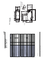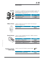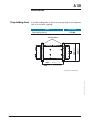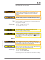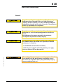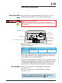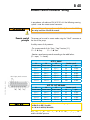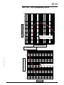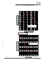
1
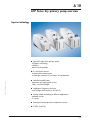
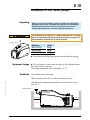
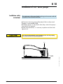
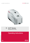
ACP Series Pompes primaires sèches Dry primary pumps Trockenlaufende Vakuumpumpen Manuel de l’Utilisateur User’s Manual Benutzerhandbuch !LCATEL6ACUUM4ECHNOLOGYASPARTOFTHE !LCATEL'ROUPHASBEENSUPPLYINGVACUUM PUMPSLEAKDETECTIONSYSTEMSVACUUM MEASUREMENTANDMICROMACHININGSYSTEMS FORSEVERALYEARS 4HANKSTOITSCOMPLETERANGEOFPRODUCTSTHE COMPANYHASBECOMEANESSENTIALPLAYER INMULTIPLEAPPLICATIONSINSTRUMENTATION 2ESEARCH$EVELOPEMENTINDUSTRYAND SEMICONDUCTORS !LCATEL6ACUUM4ECHNOLOGYHASLAUNCHED !DIXENITSNEWBRANDNAMEINRECOGNITION OFTHECOMPANYSINTERNATIONALSTANDINGIN VACUUMPOSITION 7ITHBOTH)3/AND CERTIlCATIONSTHE&RENCHCOMPANYISAN ACKNOWLEGDEDEXPERTINSERVICEAND SUPPORTAND!DIXENPRODUCTSHAVETHE HIGHESTQUALITYANDENVIRONMENTALSTANDARDS '"%DITION*UNE 7ITHYEARSOFEXPERIENCE!64TODAYHASA WORLDWIDEPRESENCETHROUGHITSINTERNATIONALNETWORK THATINCLUDESAWHOLEHOSTOFEXPERIENCEDSUBSIDIARIES DISTRIBUTORSANDAGENTS 4HElRSTSTEPWASTHEFOUNDINGOF!LCATEL6ACUUM 0RODUCTS(INGHAM-!INTHE5NITED3TATES THIRTYYEARSAGOREINFORCEDTODAYBYOTHERS53 SUBSIDIARIESIN&REMONT#!AND4EMPE!: )N%UROPE!64&&RANCEHEADQUARTERSANDTHREEOFITS SUBSIDIARIES!LCATEL(OCHVAKUUMTECHNIK'ERMANY !LCATEL6ACUUM4ECHNOLOGY5+3COTLANDAND!LCATEL 6ACUUM3YSTEMS)TALYFORMTHEFOUNDATIONFORTHE %UROPEANPARTNERNETWORK )N!SIAOURPRESENCESTARTEDINWITH!LCATEL 6ACUUM4ECHNOLOGY*APANANDHASBEEN STRENGTHENEDWITH!LCATEL6ACUUM4ECHNOLOGY+OREA IN!LCATEL6ACUUM4ECHNOLOGY4AÕWANIN !LCATEL6ACUUM4ECHNOLOGY3INGAPORE ANDMORERECENTLYWITH!LCATEL6ACUUM4ECHNOLOGY 3HANGHAI#HINAIN 4HISORGANIZATIONISROUNDEDOFFBYMORETHAN REPRESENSATIVESBASEDINAVARIETYOFCONTINENTS 4HUSWHATEVERTHECIRCUMSTANCESTHEUSERSOF!DIXEN PRODUCTSCANALWAYSRELYONQUICKSUPPORTOFOUR SPECIALISTSIN6ACUUM4ECHNOLOGY User’s manual ACP series dry primary pumps Welcome Dear customer, You have just purchased an Adixen dry primary pump. We would like to thank you and are proud to count among our customers. This product benefits from Alcatel’s many years of experience in producing vacuum products in many applications like Instrumentations, R & D, Semiconductors process. In the last field, thousands of dry pumps, based on the ACP technology are currently running. GB 00685 - Edition 08 - July 06 In order to guarantee performance and obtain full satisfaction from this equipment, we suggest that you study this manual, particularly chapter B devoted to installation and start-up, before installing or performing maintenance on your pump. APPLICATIONS: ACP 15, ACP 28 AND ACP 40 «CLEAN» APPLICATIONS DRY PRIMARY PUMPS FOR • Instrumentation • Research and Development • Semi-conductors: Load lock - Transfer chamber ACP 15 G, ACP 28 G, ACP 40 G DRY PRIMARY PUMPS FOR THE PUMPING OF CORROSIVE GAS TRACES. FEATURES: MULTI-STAGE ROOTS TECHNOLOGY UNIVERSAL SINGLE PHASE ELECTRICAL AIR COOLED SUPPLY 1/2 User’s manual ACP series dry primary pumps Copyright/Intellectual property: The use of Adixen products are subject to copyright and intellectual property rights in force in any jurisdiction. All rights reserved, including copying this document in whole or any part without prior written authorization from Alcatel Vacuum Technology France. Specifications and information are subject to change without notice by Alcatel Vacuum Technology France. 2/2 GB 00685 - Edition 08 - July 06 This product complies with the requirements of European Directives, listed in the Declaration of Conformity contained in G100 of this manual. These Directives are amended by Directive 93/68/E.E.C (E.C. Marking). General contents MANUAL REFERENCE: 112369 EDITION: 01 - July 2006 ACP Series User’s Manual Chapter A INTRODUCTION A A A A A A 10 20 30 40 41 50 - ACP Series dry primary pumps overview Operating principle Dry primary pump applications Technical characteristics - ACP 15 Technical characteristics - ACP 28, ACP 40 Accessories Chapter B INSTALLATION B B B B B B B 00 10 20 30 40 41 50 - Safety instructions Installation of ACP Series pumps Mechanical connections Electrical connections Remote control connector wiring RS 485 serial link wiring Inert gas purge connection (G version) Chapter C OPERATION C 10 - Pump operation C 20 - Detailed description of RS 485 commands Chapter D MAINTENANCE - TROUBLESHOOTING D 10 - Maintenance frequency Chapter E MAINTENANCE SHEETS E 00 - Maintenance safety instructions Chapter F COMPONENTS GB 03109 - Edition 01 - June 06 F - Non used Chapter G APPENDIX G G G G G 10 11 12 100 200 ACP 15 / 15 G - Pumping curves ACP 28 / 28 G - Pumping curves ACP 40 / 40 G - Pumping curves - Declaration of Conformity - Safety questionnaire Indicates a potentially hazardous situation which, if not avoided, could result in property damage. Indicates a potentially hazardous situation which, if not avoided, could result in moderate or minor injury. It may also be used to alert against unsafe practices. 1/2 MANUAL REFERENCE: 112369 EDITION: 01 - July 2006 General contents ACP Series User’s Manual Indicates a potentially hazardous situation which, if not avoided, could result in death or severe injury. GB 03109 - Edition 01 - June 06 Indicates an imminently hazardous situation that, if not avoided, will result in death or severe injury (extreme situations). 2/2 ! )NTRODUCTION 5SERS-ANUAL!#03ERIES $ETAILEDCONTENTS ! !#03ERIESDRYPUMPOVERVIEW 3UPERIORTECHNOLOGY -ODEL!#0'OVERVIEW -ODEL!#0''OVERVIEW ! /PERATINGPRINCIPLE -ULTISTAGE2OOTSPRINCIPLE ! $RYPRIMARYPUMPAPPLICATIONS 3TANDARDVERSIONFORhCLEANVACUUMvAPPLICATIONS 'VERSIONFORPUMPINGOFCORROSIVEGASTRACESORCONDENSABLEGAS ! 4ECHNICALCHARACTERISTICS!#0MODEL 3PECIFICATIONS $IMENSIONALDRAWING ! 4ECHNICALCHARACTERISTICS!#0MODELS 3PECIFICATIONS $IMENSIONALDRAWING ! !CCESSORIES '"%DITION*ULY )NLETFILTERS %XHAUSTSILENCER 3OUNDINCLOSURE &REQUENCYCONVERTERINTERFACEPLUG 0UMPHOLDINGDEVICE A 10 ACP Series dry primary pump overview Superior technology Type Multi-stage Roots primary pump - frictionless technology - reliability - aluminium pump body Dry and clean vacuum - no particulate contamination - residual gas spectrum free of traces of hydrocarbons GB 03110 - Edition 01 - July 06 Sealed air-cooled motor - permanent air cooling (built-in fan) - safety: certified leaktight Single-phase frequency converter - multi-voltage, dual frequency 50/60 Hz 2 pump models according to different applications - standard version - G version Thermal protection based on temperature sensors. RS 485 Serial link. 1/2 A 10 ACP Series dry primary pump overview Model ACP 15 / 15 G overview Neutral gas connection (G version) Gas ballast Hoisting ring Inlet Identification label Exhaust Clock-timer Remote control connector Start / Stop switch Neutral gas connection (G version) Electrical power supply Hoisting ring Inlet Gas ballast Start / Stop switch Exhaust Clock-timer Remote control connector Electrical power supply 2/2 GB 03110 - Edition 01 - July 06 Model ACP 28 / 28 G / 40 / 40 G overview ! /PERATINGPRINCIPLE -ULTISTAGE2OOTS PRINCIPLE ).,%4 ST34!'% 4HE!#0PUMPSARECOMPOSEDOFOR2OOTSTYPESTAGES CONNECTEDINSERIES .OCONTACTDESIGN4HEROTORSDONOTTOUCHEACHOTHERORTHE HOUSING ND34!'% RD34!'% TH34!'% TH34!'% 3),%.#%2 %8(!534 '"%DITION*ULY 4HESTANDARDPUMPSARE '!3"!,,!34 EQUIPPEDWITHAGASBALLAST DEVICETOIMPROVEPUMPINGOF LIGHTGASESANDCONDENSABLE VAPORS 4HUSAVOIDINGCONDENSATIONOF PUMPEDGASESINTOTHEPUMP TH34!'% %8(!534 3),%.#%2 ! $RYPRIMARYPUMPAPPLICATIONS 3TANDARDVERSIONFOR vCLEANVACUUMv APPLICATIONS 4HEPUMPISDESIGNEDFORAPPLICATIONSTHATREQUIRETHEPUMPINGOF CLEANDUSTFREEANDNONCORROSIVEGASES%XAMPLESARE )NSTRUMENTATION s'ASANALYSIS s%LECTRONICMICROSCOPE s8RAYSPECTROMETER s,EAKDETECTION s3URFACEANALYZER 2ESEARCHAND$EVELOPMENT 3EMICONDUCTOR&ABRICATION s,OADLOCKANDTRANSFERCHAMBERPUMPING s7AFERBACKPUMPING '"%DITION-ARCH 'VERSIONFOR PUMPINGOFCORROSIVE GASTRACESOR CONDENSABLEGAS 'VERSIONPUMPISCOMPATIBLEWITHTHEPUMPINGOFCORROSIVETRACES )TISEQUIPPEDWITHGASPURGECIRCUITSUSEDTOWITHSTANDGASTRACES TOPROTECTTHE,0AND(0BALLBEARINGSANDTHEPUMPTHIGHTNESSIS REINFORCED4HISPUMPMODELCANBEUSEDINAPPLICATIONSSUCHAS s0ROCESSMONITORING s,OADLOCKPUMPING s4RANSFERCHAMBERPUMPING s&OCUSED)ON"EAMS &ORCORROSIVEGASPUMPINGCONTACTTHEMANUFACTURER GB 02222 - Edition 05 - July 06 °C (°F) Min. ambient operating temperature °C (°F) Storage temperature Alcatel Vacuum Technology France - ACP Series User's Manual _ 5 20 23 (50.7) mini -10 (14) / maxi 60 (140) (3) oil charge has been introduced into oil casing at factory. Don’t modify this oil level. (2) relative nitrogen pressure 300 mbar (1) typical value Kg (lbs) Oil Weight cm3 DN 16 ISO-KF capacity(3) Exhaust port 180 DN 25 ISO-KF Fan flow rate 520 480 600 <5 + 12 (+ 54) + 40 (+ 104) 1200 (900) 110 / 230 V ± 10% - 50/60 Hz 10/15 A - 1150 VA _ 0.5 14 (8.2) 3 x 10 -1 (2.25 x 10 -1) 1013 (760) 3 x 10 -1 (2.25 x 10 -1) 5 x 10 -2 (3.8 x 10 -2) Inlet port m3/h slm Single phase power Automatic switch voltage (high or low) m3/h N2 flowrate(2) W Gas ballast flowrate Power consumption …………at ultimate pressure (gas ballast closed) …………at ultimate pressure (gas ballast opened) …………at atmospheric pressure mA °C (°F) Max. ambient operating temperature Leakage current mbar (Torr) mbar (Torr) Maximum exhaust pressure (absolute) m3/h (cfm) Peak pumping speed (rotation speed 6000 rpm) Maximum pressure at inlet (absolute) mbar (Torr) Ultimate pressure(1) - Standard model: with gas ballast opened - G model: with purge (300 mbar relative pressure) Ultimate pressure(1) - gas ballast closed 5 x 10 -2 (3.8 x 10 -2) II 2 mbar (Torr) ACP 15 G < 2000 (6561) Pollution degree m (ft) Indoor Installation category Functioning altitude Utilization ACP 15 1/1 Electrical power supply (0.43) 11 284 (11.22) 409 (16.14) Hoisting ring 498 (19.77) 480 (19.05) Gas ballast 300 (11.81) 239 (9.45) (3.39) 85 Dimensional drawing mm (inch) 272 (10.8) Unit 8 Specifications (0.31) Technical characteristics ACP 15 / ACP 15 G (3.74) 95 Gas line supply 1/4 connector (G model) Exhaust DN 16 ISO-KF Inlet DN 25 ISO-KF 44 150 (5.91) 15 (0.59) 190 (7.48) (1.73) A 40 207 (8.14) GB 03111 - Edition 01 - July 06 3 x 10 -2 (2.25 x 10 -2) °C (°F) _ Alcatel Vacuum Technology France - ACP Series User's Manual _ 1.2 1.65 _ _ 32 (70.5) DN 40 ISO-KF mini -10 (14) / maxi 60 (140) 30 (66) 25 DN 25 ISO-KF 410 _ 1/1 1x10⁻¹ (0.75x10⁻¹) 110 / 230 V ± 10% - 50/60 Hz 10/15 A - 1150 VA 700 1000 <5 + 12 (+ 54) + 40 (+ 104) 1.65 DN 25 ISO-KF _ 1.2 _ (3) oil charge has been introduced into oil casing at factory. Don’t modify this oil level. (2) relative nitrogen pressure 300 mbar. (1) typical value. Kg (lbs) Storage temperature cm3 Weight Oil capacity(3) Exhaust port Inlet port Fan flowrate Single phase power Automatic switch voltage (high or low) m3/h slm flowrate(2) N2 m3/h Gas ballast flowrate W °C (°F) Min. ambient operating temperature Power consumption …………at ultimate pressure (gas ballast closed) …………at atmospheric pressure °C (°F) Max. ambient operating temperature mA 1200 (900) mbar (Torr) Maximale exhaust pressure (absolute) Leakage current 1013 (760) mbar (Torr) 37 (22) Maximum pressure at inlet (absolute) 27 (16) m3/h (cfm) (0.75x10⁻¹) ACP 40G 3 x 10 -2 (2.25 x 10 -2) 2 x 10⁻¹ (1.5 x 10⁻¹) Peak pumping speed (rotation speed 4800 rpm) 1x10⁻¹ _ mbar (Torr) 2 x 10 -1 (1.5 x 10 -1) - G model : with purge (300 mbar relative pressure) Ultimate pressure(1) - Standard model : with gas ballast opened mbar (Torr) 2 mbar (Torr) Pollution degree Ultimate pressure(1) - gas ballast closed ACP 40 < 2000 (6561) Indoor ACP 28G II m (ft) ACP 28 Installation category Functioning altitude Utilization Unit 20 (0.79) Electrical power supply 278 (10.94) Exhaust DN 25 ISO-KF ACP 28 - Inlet DN 25 ISO-KF ACP 40 - Inlet DN 40 ISO-KF 309 (12.17) Inlet 450 (17.11) 627 (24.69) Hoisting rings Remote control connector 101 (3.97) Dimensional drawing mm (inch) 150 (5.9) 322 (12.68) Specifications 96 (3.78) 66 (2.6) 94 (3.7) 21.5 (0.84) (Modele G) R1/4 connector Gas line supply 228 (8.98) 11,5 (0.45) 20 (0.79) 60 67 (2.64) (2.36) Technical characteristics ACP 28 / 28 G / 40 / 40 G 272 (10.71) A 41 250 (9.84 ) (Inlet and exhaust) 193 (7.6) A 50 Accessories Inlet filter The inlet filter is installed on the pump inlet and collects particles with a diameter greater than 25 microns (vacuum packing, metallurgy, lamp manufacture, evaporation, etc.). Model Exhaust silencer IPF 25 (for ACP 15/28) 111 649 IPF 40 (for ACP 40) 111 647 In order to reduce noise level at the exhaust when the pump is operated at high pressures. Model In order to reduce significantly noise level (- 5 dBA) in maximum ambiant temperature of 35 °C. GB 03112 - Edition 01 - June 06 Model Frequency converter interface plug Part number 109 873 Silencer ES25S Sound inclosure Part number Part number NRC 28-40 for ACP28/ACP40 112 637 NRC15 for pump ACP 15 111 968 Sound enclosure (-10 dBA) for ACP 15 112 779 In order to recover the information «pump at speed» ( Model Frequency converter interface plug B40) Part number 112 581 1/2 A 50 Accessories Pump holding device It includes holding plates to fasten to the pump body on the equipment (M6 screw customer supplied). Model Part number 112 846 Pump holding device 254 (10) 240 (9.45) Holding plates 300 (11.8) (ACP 15) 450 (17.7) (ACP 28-40) GB 03112 - Edition 01 - June 06 Dimensions mm/(inch) 2/2 Installation B User’s Manual ACP Series Detailed contents B 00 Safety instructions - Unpacking - Installation and start-up - Operation B 10 Installation of ACP Series pump - Unpacking Equipment storage Ventilation Installation safety instructions B 20 Mechanical connections - Inlet - Exhaust B 30 Electrical connections - General - Rear panel of the pump - Circuit breaker B 40 Remote control connector wiring - Remote control principle - Wiring of the remote control plug - Wiring of output S2 GB 03119 - Edition 01 - July 06 B 41 RS 485 serial link wiring - Factory configuration - RS 485 connector wiring - RS 485 serial link B 50 Inert gas purge connection (G version) - Gas line connection - Nitrogen flowrate adjustment 1/1 B 00 Safety instructions Indicates a potentially hazardous situation which, if not avoided, could result in property damage. Indicates a potentially hazardous situation which, if not avoided, could result in moderate or minor injury. It may also be used to alert against unsafe practices. Indicates a potentially hazardous situation which, if not avoided, could result in death or severe injury. Indicates an imminently hazardous situation that, if not avoided, will result in death or severe injury (extreme situations). Before switching on the pump, the user should study the manual and follow the safety instructions listed in this manual. Unpacking To keep your product in the clean condition in which it left our factory, we recommend unpacking the pump at the site of installation. GB 00224 - Edition 04 - July 06 Make sure that the equipment has not been damaged during the transport. It it has been damaged, take the necessary steps with the carrier and inform the manufacturer if necessary. In all cases, we recommend that you keep the packaging (reprocessing material) to transport the equipment or for prolonged storage. Installation - Start up Our products are designed to comply with current EEC regulations. Any modification of the product made by the user is liable to lead to noncompliance with these regulations, or reduce the EMC (electromagnetic compatibility) performance and the safety of the product. The manufacturer declines any responsibility for such operations. 1/3 B 00 Safety instructions Installation - Start up (ctd) Before performing any maintenance operations on the product, isolate the product from the various energy sources (electricity, compressed air, etc). The EMC performance of the product is obtained on the condition that the installation complies with EMC rules. In particular, in disturbed environments, it is essential to: - use shielded cables and connections for interfaces, - stabilize the power supply line with shielding from the power supply source to a distance of 3 m from the product inlet. When switching off an item of equipment containing loaded capacitors at over 60 VDC or 25 VAC, take precautions concerning the access to the connector pins (single-phase motors, equipment with line filter, frequency converter, monitoring unit, etc.). Wait 1 minute after pump switch off before operating on the product. Risk of tilting over: although compliance with EEC safety regulations is guaranted (normal range ± 10°), it is recommended to take precautions against the risk of tilting over during handling, installation and operation. The vacuum pump is also a compressor: incorrect use may be dangerous. Study the user manual before starting up the pump. Make sure that the parts or chambers connected to the inlet of our pumps withstand a negative pressure of 1 bar in relation to the atmospheric pressure. 2/3 GB 00224 - Edition 04 - July 06 The performance and the operational safety of this product are guaranteed provided that it is used in normal operating conditions. B 00 Safety instructions Operation The air tightness of the products is guaranteed when they leave the factory for normal operating conditions. It is the user's responsibility to maintain the level of airtightness particularly when pumping dangerous gases. The ACP Series G version are made to pump on corrosive gas traces. The manufacturer has no control over the types of gases passing through this pump. Frequently, process gases are toxic, flammable, corrosive, explosive or otherwise reactive. Since these gases can cause serious injury or death, it is very important to plumb the exhaust of the pump to the facility's hazardous gas exhaust system which incorporates approppriate filters, scrubbers, etc., to insure that the exhaust meets all air regulations. Check that pump is correctly connected to the equipment. The pumps are designed so as not to present a thermal risk for the user's safety. However, specific operating conditions can generate temperatures which require particular care to be taken by the user (external surfaces > 70°C). GB 00224 - Edition 04 - July 06 The ACP pumps must not be operated in an area with risk of explosion. Consult us to study a solution. 3/3 B 10 Installation of ACP Series pumps Unpacking When you receive the equipment, unpack it carefully; do not discard the packaging until you have ensured that the pump has not been damaged during transport. Otherwise, take the necessary measures with the transporting company and, if necessary, notify the manufacturer. For all handling of the equipment, it is highly recommended to use a lifting device. Use the hoisting rings delivered with the pump by screwing them in the threated holes located on the top side of the pump. Hoisting rings Model type Weight ACP 15/15 G 23 kg ACP 28/28G 30 kg ACP 40/40G 32 kg If necessary the hoisting rings can be removed from the housing. Equipment storage If the new pump is to be stored, the plugs on the inlet and exhaust ports must remain in position. The storage temperature must not be below -10 °C. Ventilation Vents at both ends of the pump. GB 03113 - Edition 01 - July 06 Place the pump at least 80 mm from the stationary section. The ambient air temperature particularly near the fan must be less than 40 °C. SINGLE-PHASE FREQUENCY CONVERTER 3.15 inch mini 3.15 inch mini t ≤ 40 °C 1/2 B 10 Installation of ACP Series pumps Installation safety instructions The performance of the pump depends on the type of accessories used and the quality of the mechanical connection. Determine where the pump will be placed. Refer to dimensional diagram in section A 40 or A 41. Install the pump in a way that the Start/Stop switch of the pump is accessible for the operator. After pump connection, it is necessary to perform an helium leak tightness test. The pump must be operated in the horizontal position with the pumping axis vertical and the inlet operating upwards. horizontal surface 2/2 GB 03113 - Edition 01 - July 06 Inlet B 20 Mechanical connections Remove the blanck offs blocking the inlet and exhaust ports: these components prevent foreing bodies from entering the pump during transport and storage. It is dangerous to leave them on a pump in operation. For safety reasons, use accessories on the inlet and exhaust lines whose materials and sealing properties are compatible with the gases being used. Inlet Connection type Connect the pump inlet to the equipment with connecting accessories (see manufactrer’s catalog). - ACP 15 / 28 model: DN 25 ISO-KF. - ACP 40 model: DN 40 ISO-KF. The maximum inlet pressure is the absolute atmospheric pressure. A pressure too high can damage the pump. In case of applications involving dust or solid particules, we recommend to use appropriate inlet filters in order to protect the pump ( section A 50). Also, we advise to use clean fittings and pipings for connecting the pump to the installation. GB 00823 - Edition 06 - July 06 Exhaust When pumping on corrosive gas traces, or aggressive gases (pump G version), the gas can cause injury or death. The exhaust of the pump must be connected to an exhaust stack or an evacuation duct. Make sure that the exhaust pressure does not exceed 1200 mbar (absolute pressure). A pressure too high can damage the pump. Connection type - ACP 15 model: DN 16 ISO-KF. - ACP 28 / 40 model: DN 25 ISO-KF. Several fitting accessories are available in the manufacturer’s catalog. 1/1 B 30 Electrical connections General Our products are designed to comply with current EC regulations. Any modification of the product made by the user is liable to lead to noncompliance with these regulations, or to reduce the EMC (ElectroMagnetic Compatibility) performance and the safety of the product. The manufacturer declines any responsability for such operations. The performance and the operational safety of this product is guaranteed provided that it is used in normal operating parameters defined in this manual. Any modification of the pump not improved by the manufacturer can compromise the protection ensured by the pump. The EMC performance of the product is obtained on the condition that the installation complies with the EMC rules. In particular, in disturbed environments, it is essential to: - use shielded cables and connections for interfaces, GB 00695 - Edition 05 - July 06 - stabilize the power supply line with meshing from the power supply source to a distance of 3m from the pump inlet. When switching off an item of equipment containing capacitors loaded at over 60 VDC or 25 VAC, take precautions concerning the access to the connector pins (single-phase motors, fitting with line filter, frequency converter, monitoring system, etc.). 1/2 B 30 Electrical connections Rear panel of the pump In accordance with recommandations of EN 61010-1+ A2, the following warning symbol is on the variator inside the pump. Warning: risk of electrical shock. Voltage or current hazard sufficient to cause shock. Disconnect and lockout power before servicing. Any intervention must be done by trained personnel only. Start/Stop switch Electrical power supply 0 Clock-timer Frequency converter label Remote control connector Identification label Electrical motor is in accordance with CE standards offers the following voltage range: Model ACP 15 ACP 28 / 40 Voltage range 110 V / 230 V 50/60 Hz 10 A / 5 A 1150 VA allows automatically low or high voltage pump running, according to range voltage 110 V to 230 V, 50/60 Hz. The pump supplying cable is provided with the pump delivered. The earthing of the pump (frequency converter, covers, body of the pump) is realized by the cable connected with the network customer. The network customer should have himself a connection in the ground. Circuit breaker An 6 A circuit breaker is recommended for high voltage, 230 VAC + 10 %. A 12 A circuit breaker is recommended for low voltage, 110 VAC + 10 %. The pump is equipped with thermal sensors which stops pump starting-up depending on the temperature ( C 10). 2/2 GB 00695 - Edition 05 - July 06 The motor is equipped with an electrical frequency converter which B 40 Remote control connector wiring In accordance with advice of EN 61010-1+A2 the following warning symbol is near the remote control connector: Before switching on the pump, the user should study the manual and follow the safety instructions listed in this manual. Remote control principle The pump can be used in remote mode using the “Sub-D” connector at the rear of the pump. Used by means of dry contacts: - The remote control of the “Start / Stop” function (S1). S1 = 0 Stop S1 = 1 Start. - Rotation speed remote control according to the table below: (O = open, 1 = closed): ACP 15 Model S3 S4 S5 Contact status Contact status Contact status GB 03114 - Edition 01 - July 06 DB 15 pins, male connector Rotation speed Hz rpm S3 = 1 S4 = 0 S5 = 1 60 3 600 S3 = 1 S4 = 0 S5 = 0 70 4 200 S3 = 0 S4 = 1 S5 = 1 80 4 800 S3 = 0 S4 = 1 S5 = 0 90 5 400 S3 = 0 S4 = 0 S5 = 1 95 5 700 S3 = 0 S4 = 0 S5 = 0 100 6 000 ACP 28 - ACP 40 Model S3 S4 S5 Contact status Contact status Contact status Rotation speed Hz rpm S3 = 1 S4 = 1 S5 = 0 42 2 500 S3 = 1 S4 = 0 S5 = 0 50 3 000 S3 = 0 S4 = 1 S5 = 0 65 3 900 S3 = 0 S4 = 0 S5 = 0 80 4 800 For pump safety, do not exceed the maximum frequency: 100 Hz for ACP 15 models, 80 Hz for ACP 28/40 models. N t Ch Note: Changing i the th rotational t ti l speed d will ill affect ff t the th pumping i speed d and the ultimate pressure. 1/3 B 40 Remote control connector wiring Wiring of the remote control plug S1, S3, S4 and S5 are inputs. S2 is an output (open collector). Pump connection Equipment connection S1: start/stop S2 closed: pump at speed S3, S4, S5: rotational speed selection C Pin 8, 10, 12 and 14 are connected to the ground of the control unit. GND 1 1 2 2 3 3 4 4 5 5 6 6 7 7 8 8 9 9 10 10 11 11 12 12 13 13 14 14 15 15 S2 output S1 start/stop S3 Speed selection S4 S5 Do not add any strap except S1, S3, S4 and S5. Wiring of output S2 S2 is an open collector output and must be wired as shown below. Vcc is a direct voltage (between 7 and 30VDC) supplied by the user. The value of the resistance R depends on the customer installation. Frequency converter Connector Sub-D Vcc R 5 I Vout C 2/3 GB 03114 - Edition 01 - July 06 Output S2: Do not connect a relay between the pins 5 and 6. The relay coil induces a current which may result in damage of the frequency converter unit. Wiring of output S2: The maximum value of the current in the output must be of 35 mA. 6 B 40 Remote control connector wiring Vcc and R values must be calculated so as not to exceed a current value of 35 mA. Higher current will damage the frequency converter. When the nominal speed is reached, the transistor becomes conductive («on-state») and Vout = 0 V. As long as the nominal speed is not reached, the transistor is blocked («off-state») and Vout = Vcc. This circuit can not be used for power transfer. For switching of power circuits an amplification stage is required. This is an example that correspond to the remote interface plug available as an accessory ( A50). It allow to use output S2 as a relay (dry contact). +5V Pump side R1 11123 47K 0603 R2 10723 1K0 0603 15 14 13 12 11 10 9 8 7 6 5 4 3 2 1 36591 B C807 S O T23-3 4 3 2 2RT 47721 K 1 5 6 7 1 8 15 14 13 12 11 10 9 8 7 6 5 4 3 2 1 47710 15p R3 C R1 +5V 47691 0,5A 1 3 2 Z1 47561 +5V GND NC 5 2 3 GND IN GND OUT GN D 1 C2 42452 0603 100nF L 78L05C SO-8 6 35964 B AT54C SOT23-3 NC 47700 15p J1 Q1 4 GB 03114 - Edition 01 - July 06 J2 Customer equipment side 7 Wiring example 8 C1 42452 0603 100nF 3/3 B 41 RS 485 serial link wiring Factory configuration The serial link allows to control and monitor several pump in a network. • Transmission speed: 9600 bauds • Data lenght: 8 bits • Parity: none • Stop bit: 1 V-(B) (RS 485) RS 485 connector wiring V+(A) (RS 485) +5 V DB 15 pins, male connector (soldered view) RS 485 serial link Several units (up to 255) can be controlled on a single link. It’s a parallel type connection which allows communication in the network even if a pump is disconnected. G 03115 - Edition 01 - July 06 RS 485 communication box V-(B) V+(A) 1.5 kΩ 1/4 W Wiring of the unit at the end of the line , or when there is one and only unit in the link. 1.5 kΩ 1/4 W 1/1 B 50 Inert gas purge connection (G version) Gas line connection For optimum performances -ball bearing protection-, the nitrogen supply should have the following characteristics: - Maximum moisture rate: 5 ppm of water - Dust < 1μm - Oil < 0.1 ppm - Pressure:1.5 bar absolute (before the gas pressure reducing valve, customer supply) Connect the gas line supply to the R 1/4 connector provides on purpose with flexible or stainless steel pipe (customer supply). Note : we recommend to install an isolation valve on the gas supply line, nearest the inlet gas port to allow pump performance recovering when the gas line is not used ( A 40, A 41). For optimum ball bearing protection, the neutral gas pressure must be set to 0.3 bar (relative pressure) according to the flowrate value given in the table below: GB 00697 - Edition 05 - July 06 Nitrogen flowrate adjustment ACP 15 ACP 28/40 Flowrate max (slm) 5 1.65 Ultimate pressure (mbar) 3 x 10⁻¹ 1 x 10⁻¹ e.g: ACP 28 G Gas line supply R 1/4 connector 1/1 Operation C User’s Manual ACP Series Detailed contents C 10 Pump operation - C 20 Pump temperature for start-up condition Operation in local mode Operation in remote mode Pump start-up Pumping of condensable vapors Pump stop Detailed description of RS 485 commands GB 03120 - Edition 01 - July 06 - Conventions applicable to the syntax of all commands - The commands 1/1 C 10 Pump operation The ACP Series uses a specific gear oil. The amount required for pump operation is set at in the factory. Do not modify this oil level. Pump temperature for start-up condition Operation in local mode The pump is equipped with thermal sensors. When switching on the pump, if the temperature is: - less than 12 °C, - or over than 40 °C, the pump doesn’t start, but the fan is energized. The pump will start automatically when the ambient temperature is back in the authorized temperature range. In local mode, the pump can run only if the cover plug (delivered with the pump) is fitted on the remote control connector. Wiring of the Remote cover plug 8 7 15 6 14 5 13 4 12 3 11 2 10 1 9 GB 03116 - Edition 01 - July 06 DB 15 pins, male connector (soldered side view). Factory wired with appropriate jumper for local operation. Operation in remote mode Note Pump start-up The pump can be used in remote mode: • if the Remote control plus is wired according to instructions given in B40. B 41). • if the RS485 serial link is wired ( It’s the origin of Start/Stop control which has priority on the speed selection: - when the Start/Stop is made by the remote control cover plug, the selected speed corresponds to the dry contact setting, - when the Start/Stop is made by RS485 serial link, the speed corresponds to the speed set point defined on serial link. Pump is equipped with a main power switch. The pump starts up when the power line cord is connected, and main switch is on “1” position. A time counter displays the pump running time in hour. 1/2 C 10 Pump operation Avoid sudden changes in ambient temperature when the pump is running. Neutral gaz purging is imperative for the pumping of corrosive gas traces. The pumps are designed so as not to present a thermal risk for the user’s safety. However, specific operating conditions can generate temperatures which require particular care to be taken by the user (external surfaces > 70°C). Pumping of condensable vapours In order to better handle condensable vapours, it is necessary to pump with a hot pump. It is recommended to isolate the pump from the installation and let the pump run for at least 1 hour, with gas ballast opened. Then open the isolation valve, the pump will operate in optimized conditions, thus reducing the risk of condensation inside the pumping module. Operation of gas ballast • Knob screwed: gas ballast closed. • Knob unscrewed: gas ballast opened. Before switching off, isolate the pump from the installation and let it run for 1 hour with gas ballast opened. Put the main switch on « O » position or press the circuit breaker of the customer’s installation. When the pump is remote controlled, the pump will be stopped by opening the « Start/Stop » contact ( B40). When the pump is controlled by RS 485 serial link, the pump will be stopped by sending the appropriate command ( C 20). 2/2 GB 03116 - Edition 01 - July 06 Pump stop Clic ! C 20 Detailed description of RS 485 commands Conventions applicable to the syntax of all commands Status values Error messages ADR Syntax Result GB 03117 - Edition 01 - July 06 Syntax Result IDN Syntax Result Adr = address, from 000 to 255 <CR> Carriage return (ascii 13) <LF> line Feed (ascii 10), between square brackets ; this character is not compulsory # hash sign (ascii 35) , comma (ascii44) Ok : command executed correctly Err0: Err1: Err2: Err3: adjustment error (out of bounds) command error (syntax) parameter error (eg. Non-hexadecimal character.) context error Specifies the address of the device for networking #adrADRaaa<CR>[LF] adr = product address before the command aaa = new address of the product condition : 000 ≤aaa ≤255 #aaa,ok or Err2 This command is used to allocate a specific number to each of the products making up a network. It’s important to record each product address. When the address of the product is unknown, it’s possible to recover the product address using ADR command but only this pump must be connected on the link RS 485. # ???ADR <CR>[LF] ??? chain of three ascii characters. #adr,ok OK means command received, adr is the product address. Identifies the device which is communicating and its software version #adrIDN<CR>[LF] #adr, VPxxxxx – Vx.zz Return the type of pump, ACP15, ACP28 or ACP 40 depending on the variator, the software version (x) and software release (zz). Ex : #004,ACP28– V1.03: product address 004 controls ACP 28 with a software release V1.03. 1/3 C 20 Detailed description of RS 485 commands NSP Syntax Result RPM Syntax Switches the speed set point to the nominal speed value #adrNSP<CR>[LF] This command allows to restore the nominal speed to the default value : (80 Hz for ACP 28/40 and 100 Hz for ACP 15). #adr,ok Defines the speed set point in stand-by mode #adrRPMnnnn<CR>[LF] nnnn speed value in rpm Set point speed from 2100 rpm ( 35 Hz) ( to maximum speed by step of 10 rpm. Max. speed : ACP15: 6000rpm (100 Hz) ; ACP 28/40 or RVP : 4800 rpm (80 Hz). Note: you must send the SBY command, before changing the pump rotational speed using RPM command. Result SBY Syntax #adr, ok or #adr, Errx x = 1 out of range, 2: parameter error , 3: context error. Switches the speed set point to the stand-by value #adrSBY<CR>[LF] Resets the stand-by speed to the default value (35Hz for all pump models). #adr, ok Note : you must send the SBY command before changing the pump rotational speed using the RPM command. ACP Syntax Result 2/3 Defines the operating status of the pump #adrACPON<CR>[LF] : start pump rotation #adr OFF<CR>[LF] : stop pump #adr, ok or #adr, Err3 if the pump is already in the requested state (context error). GB 03117 - Edition 01 - July 06 Result C 20 Detailed description of RS 485 commands STA Syntax Result Returns the state of the internal dynamic parameters #adrSTA<CR>[LF] #adr,xxxxxx,yyyyyyy,zzzzzz,sssss,iii,www,ppp,vvv,tttt<CR>[LF] adr: address xxxxxx,yyyyyy,zzzzzz codified information under 6 decimal figures (0 or 1 depending on conditions: 543210 x x x x x x state bits 5 - reserved ( 0) 4 - reserved (0) 3 - Pump running (1), pump stopped (0) 2 - standby speed (1), nominal speed reached (0) 1 - standby mode (1), other (0) y y y y y y fault bits 5 - power transistor non controlled (copy of red LED =1), otherwise (0) 4 - motor temperature too high (1) 3 - motor current too high (1) 2 - reserved (0) 1 - reserved (0) 0 - reserved (0) GB 03117 - Edition 01 - July 06 z z z z z z alert bits 5 - reserved (0) ; 4 - reserved (0) ; 3- reserved ( 0) ; 2 - reserved (0) ; 1- reserved (0) ; 0 - reserved (0) sssss: current speed value in rpm, codified on 5 decimal figures (eg: speed 05600 rpm: sssss = 05600) iiii: Motor power in Watts, codified on 4 decimal figures (eg: power 450 W: iiii = 0450) www: reserved ppp: variator temperature codified on 3 decimal figures (eg:variator temperature 56 °C: ppp = 056) vvv: reserved tttt: pump operating time value (since first start up), codified on 4 decimal figures (eg: operating time 4568 hours: tttt = 4568). 3/3 $ 5SERS-ANUAL!#03ERIES $ETAILEDCONTENTS -AINTENANCESCHEDULE '"%DITION*ULY $ -AINTENANCE4ROUBLESHOOTING $ -AINTENANCESCHEDULE -/$%, !#0 4)-).' %6%29x H OR YEARS $%3#2)04)/. #OMPLETEMAINTENANCE - !#0 !#0 H OR YEARS sOILDRAINING s,0AND(0BEARINGREPLACEMENT sSEALREPLACEMENT #ALL CUSTOMER 3ERVICE 4HEMANUFACTURER#ENTER3ERVICEADRESSLISTATTHEBACKOFTHECOVER-ANUAL '"%DITION-ARCH -AINTENANCEFREQUENCIESARETYPICALVALUESFORNONCORROSIVE APPLICATIONS&ORAPPLICATIONSUSING'PUMPVERSIONSTHESEVALUESCAN BEREDUCED#ONTACTUS - 0ERFORMEDBYTHEMANUFACTURER % -AINTENANCESHEETS 5SERS-ANUAL!#03ERIES $ETAILEDCONTENTS % 3AFETYINSTRUCTIONSRELAREDTOMAINTENCE '"%DITION*ULY 3AFETYINSTRUCTIONS 0ROCEDUREFORRETURNINGVACCUMPUMPS E 00 Safety instructions related to maintenance Safety instructions Hazardous voltage enclosed. Voltage or current hazard sufficient to cause shock. Disconnect and lockout power before servicing. Any intervention must be done by trained personnel only. “G” version Remaining process gases in the pump may cause severe injury or death. Before removing the pump, continue N2 flow from the process tool for 30 min. Nitrogen pressure and flow rate should be identical to the programmed values during process. During pump removal, operator could be in contact with process residues on the exhaust which could cause severe injury or death. Ask your safety department for instructions according to the local statements. Recommandations GB 03118 - Edition 01 - July 06 Purge the installation with dry nitrogen. Wear gloves, protective glasses and, if necessary, a breathing mask. Ventilate the premises well. Do not dispose of residue, if necessary, have it destroyed by a qualified organization. Oil drain. The oil drain is performed during pump overhaul by manufacturer’s trained personnel. 1/2 E 00 Safety instructions related to maintenance Procedure for returning vacuum pumps No contaminated pump Fill in the safety questionnaire ( G 200) and return it with the product to the service center (see adresses at the back of the manual). Close the inlet and exhaust pipe with black plastique cap, supply with the pump. Contaminated pump Refer to safety instructions listed on page 1. Close the inlet and exhaust pipe of the pump with the following connecting accessories (avalaible in manufacturer’s catalog): Accessories How us to contact DN 16 ISO-KF DN 25 ISO-KF DN 40 ISO-KF Centering ring with O-ring 068 193 068 189 068 194 Stainless steel blank flange 068 195 068 196 068 197 Clamp 083 333 083 264 087 163 The full overhaul must be performed by manufacturer trained personnel. Contact manufacturer nearest service center or the service support at the following e-mail address: GB 03118 - Edition 01 - July 06 [email protected] 2/2 ' !PPENDIX 5SERS-ANUAL!#03ERIES $ETAILEDCONTENTS ' !#0'PUMPINGCURVES ' !#0'PUMPINGCURVES ' !#0'PUMPINGCURVES $ECLARATIONOFCONFORMITY ' 3AFETY1UESTIONNAIRE '"%DITION*ULY ' G 10 ACP 15 / 15 G pumping curves 10 ACP 15 ACP 15 G, purge 300 mbar 5 100 Hz 0 100 Hz Pumping speed (m3/h) 15 10-2 10-1 10 1 1 10 2 10 3 Inlet pressure (mbar) Pressure drop volume = 1m3 103 ACP 15 ACP 15 G, purge 300 mbar Pressure (mbar) GB 02225 - Edition 04 - July 06 102 101 1 10-1 10-2 0 10 20 30 40 50 60 70 80 90 Time (mn) 1/1 G 11 ACP 28 / 28 G pumping curves 40 35 30 Pumping speed (m3/h) 25 20 15 10 ACP 28 ACP 28 G, purge 300 mbar 80 Hz 0 80 Hz 5 10-2 10-1 10 1 1 10 2 10 3 Inlet pressure (mbar) Pressure drop volume = 1m3 103 Inlet pressure (mbar) GB 00958 - Edition 06 - July 06 102 101 ACP 28 ACP 28 G, purge 300 mbar 1 10-1 10-2 0 10 20 30 40 50 60 70 80 90 Times (mn) 1/1 G 12 ACP 40 / 40 G pumping curves 40 35 Pumping speed (m3/h) 30 25 20 15 10 ACP 40 ACP 40 G, purge 300 mbar 0 80 Hz 80 Hz 5 10-2 10-1 10 1 1 10 2 10 3 Inlet pressure (mbar) Pressure drop volume = 1m3 103 Inlet pressure (mbar) GB 02226 - Edition 04 - July 06 102 101 ACP 40 ACP 40 G, purge 300 mbar 1 10-1 10-2 0 5 10 15 20 25 30 35 40 45 Time (mn) 1/1 '"%DITION*ULY ' G 200 Safety questionnaire Procedure for returning ADIXEN vacuum pumps and helium leak detectors You wish to return an Alcatel vacuum pump or helium leak detector for maintenance. The equipment will be dismantled and possibly cleaned by a technician from our Service Centre. In compliance with European Community’s L360 directives, French labor code L231 - R231 and Federal OSHA Safety Standard 1910-1200, Alcatel Vacuum Technology requires this form to be completed to preclude the potential health risk to its service personnel that can occur when receiving, disassembling, or repairing potentially contaminated products. Equipment returned without this form completed and secured to outside of package will be returned to customer unprocessed. Equipment must be drained of fluids and residue, securely packaged and shipped prepaid. Concerning the closing of the ports (inlet & outlets of the product), metallic airtight blank flanges should be used if toxic or copper gases have been pumped. We wish to draw your attention to the following points: • The risk may be of the following nature: GB 00956 - Edition 03 - April 06 - Chemical: Danger to health, risks of explosion, fire, risks for the environment. Please indicate the chemical formula and name of the gases or substances that have been in contact with the equipment (pump or helium detector). - Biological: Pathogenic germs, micro-organisms (bacteria, viruses, etc.) classes 1 to 4 and group E. We are currently unable to deal with contamination of this sort without risk to the safery of our staff. If your equipment has been contaminated in this way, contact us so that we can try to find a solution together. - Radioactive: Contact us in this case. - Copper contamination: Copper based by products formed in sputtering or etching processes are considered as a poison in some semi-conductor processes. In the event of chemical contamination, please indicate the following gases or substances: Gases introduced A Substances produced by reaction Reactor B C Exhaust A B C Pump or pump unit · Gases (or substances) introduced into the reactor and which may be found at the exhaust (A). · Gases (or substances) resulting from the reaction or process (B). · Gases (or substances) that may possibly be formed inside the pump (due to a thermodynamic or chemical reaction, condensation, deposition, precipitation, etc.) (C). •· Precautions need to be taken before transferring contaminated pumps. Please contact customer service for recommendations. 1/2 QUESTIONNAIRE DE SECURITE SAFETY QUESTIONNAIRE Ce questionnaire est téléchargeable sur le site : www.adixen.com This questionnaire can be downloaded from: www.adixen.com Procédure de retour des Pompes à Vides et Détecteur de Fuite à Hélium ADIXEN (Ce formulaire ne peut être rempli et signé que par une personne habilitée) Procedure for returning ADIXEN Vacuum Pumps and Helium Leak Detectors (This questionnaire is only to be filled in and signed by an authorized person) SOCIETE - COMPANY EQUIPEMENT - EQUIPEMENT Nom Société – Name of company : Description : G 200 Nom personne – Name of person: (Qui remplit ce formulaire) – (Who has filled in questionnaire) Fonction – Position : N° de Série – Serial no : N° Tél. – Tel. no : Type de procédé – type of process : N° Fax – fax no: (Pour renseignements éventuels sur les produits utilisés) – (for any information on products used) (Pour lequel l’équipement est utilisé) – (for which equipment is used) Date de l’expédition – Date of consignment : INTERVENTION - SERVICE Intervention souhaitée (Révision, réparation,…) – Service required(overhaul, repair, etc.): Type d’anomalie constatée – Type of anomaly observed : N E M I C PROCEDE CUIVRE – COPPER PROCESS Produit utilisé sur un procédé Cuivre – Product used on a Copper process ASPECT SECURITE – SAFETY ASPECT Oui – Yes Non – No L’équipement mentionné ci-dessus a été en contact avec les produits suivants – The above equipment has been in contact with the following substances : (nom et formule chimique) – (name and chemical formula) Ces produits présentent un risque de nature E P S Chimique – Chemical Toxique – Toxic Cancérigène - Carcinogenic Combustible - Combustible Corrosive - Corrosive Explosive - Explosive Biologique – Biological Radioactive – Radioactive Autre – Other Oui – Yes Oui – Yes Oui – Yes Oui – Yes Oui – Yes Oui – Yes Oui – Yes These susbstances present the following risks Explication détaillée – Detailed explanation Si “Oui” risque de nature – If “Yes”, what type of risk Non – No Non – No Non – No Non – No Non – No Non – No Non – No (Vous reporter éventuellement à la page précédente) – (See preceding page if necessary) Vous avez répondu “Oui” à une des questions précédentes : Je confirme que seules les substances précisées ont été en contact avec l’équipement sus-mentionné, et que les procédures de préparation, d’emballage,et de transport ont été respectées. Je confirme que le matériel sus-mentionné n’a été en contact avec aucune substance dangereuse, et a été vidé de son huile. (Si applicable) I confirm that the above equipment has not been in contact with any dangerous substance and has been emptied of oil. (if applicable) You have replied “yes” to one of the above questions: I confirm that only the substances mentioned have been in contact with the above equipment and that the preparation, packing and transport procedures have been complied with. Réponse “Non” (sans risque) Reply “No“ (no risk) Réponse “Oui” (fermeture étanche de l’aspiration et du refoulement) Reply «Yes« (seal inlet and outlet ports with blank flanges) Nom - Name : Nom - Name : Fonction - Position : Fonction - Position : Date : Date : Signature autorisée – Authorised signature : Signature autorisée – Authorised signature : Tampon / Cachet Stamp / Seal Tampon / Cachet Stamp / Seal ALCATEL Vacuum Technology France – 98, avenue de Brogny – B.P. 2069 – 74009 ANNECY CEDEX Tél. (33) 4 50 65 77 77 – Fax (33) 4 50 65 75 77 Web site: www.adixen.com 2/2 GB 00956 - Edition 03 - April 06 SIGNATURE CHINA Alcatel Vacuum Technology, Shanghai N°82 Lane 887 Zuchongzhi Road Zhangjiang High-Tech Park, Shanghai 201203 - P.R. China Tel. (86) 21 5027 0628 Fax. (86) 21 3895 3815 FRANCE Alcatel Vacuum Technology France 98, avenue de Brogny - BP 2069 74009 Annecy cedex Tel. (33) 4 50 65 77 77 Fax. (33) 4 50 65 77 89 GERMANY Alcatel Hochvakuumtechnik GmbH Am Kreuzeck 10 - Postfach 1151 97877 Wertheim Tel. (49) 9342 9610 00 Fax. (49) 9342 9610 30 ITALY Alcatel Vacuum Systems Via Trento, 30 20059 Vimercate (Mi) Tel. (39) 0396 86 38 55 Fax. (39) 039 66 71 25 JAPAN KOREA Alcatel Vacuum Technology Korea 447 Banwol-dong, Hawsung-si, Kyungki-do 445-330, Korea Tel. (82) 031-206-6277 Fax. (82) 031-204-6279 SINGAPORE Alcatel Singapore Pte Ltd 49 Jalan Pemimpin #01-01 APS Industrial Building 577203 Singapore Tel. (65) 62540828 Fax. (65) 62547018 TAIWAN Alcatel Vacuum Taïwan No. 169-3, Sec.1, Kang-Leh Rd Song-Lin Village, Hsin-Feng 304 Hsin-Chu County, Taiwan -R.O.C. Tel. (886) 35599230 Fax.(886) 35599231 UNITED KINGDOM Alcatel Vacuum Technology UK Ltd 8 Bain Square Kirkton Campus Livingston - West Lothian EH54 7DQ Scotland Tel. (44) 1 506 418 000 Fax. (44) 1 506 418 002 USA Alcatel Vacuum Products 67, Sharp Street Hingham - MA 02043 Tel. (1) 781 331 4200 Fax. (1) 781 331 4230 Alcatel Vacuum Technology France - 98, avenue de Brogny - BP 2069 - 74009 Annecy cedex - FRANCE Tel. (33) 4 50 65 77 77 - Fax. (33) 4 50 65 77 89 Web site: www.adixen.com Realization: www.axess-groupe.com Publication: Alcatel - Part number: 112 369 - Ed.01 - 07/2006 Alcatel Vacuum Technology Japan 4-3-10 Shimokodanaka, Nakahara-ku Kawasaki, Kanagawa 211-0041 Tel. (81) 44-797-5920 Fax. (81) 44-797-5932