1
MSR400
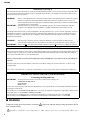
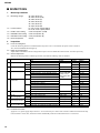
■ IC BLOCK DIAGRAM(IC ブロック図)
• NJM2068L-D (AAX64880)
INPUT: IC102
MIX: IC103, IC104, IC105, IC106, IC107, IC108, IC109
Operational Amplifier
A
1
+
+
2
3
OUT –IN +IN
A
A
A
4
–V
5
6
B
7
8
+IN –IN OUT +V
B
B
B
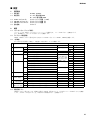
■ DISASSEMBLY PROCEDURES
■ 分解手順
• Preparing
A screwdriver with a long shaft is required to remove some
screws.
• 準備
一部のネジの取 り 外 し には、軸が長い ド ラ イ バーが必要で
す。
220mm or more
1.
Amplifier Assembly
1.
アンプ Ass’y
(Time required: about 5 minutes)
( 所要時間:5 分 )
1-1.
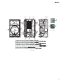
Remove the twelve (12) screws marked [21]. The amplifier
assembly can be removed. (Fig.1)
1-1.
[21] のネジ 12本を外 し 、ア ンプ Ass’y を外 し ます。( 図 1)
2.
Rear Cabinet and Front Cabinet
2.
リアキャビネットとフロントキャビネット
(Time required: about 10 minutes)
Remove the eighteen (18) screws marked [18]. The front
cabinet can then be removed from the rear cabinet. (Fig.1)
2-1.
[18] のネジ 18 本を外 し 、 リ ア キ ャ ビ ネ ッ ト か ら フ ロ
ン ト キ ャ ビ ネ ッ ト を外 し ます。 ( 図 1)
3.
Woofer (Time required: about 15 minutes)
3.
ウーファー (所要時間:15 分 )
3-1.
Remove the front cabinet from the rear cabinet. (See
procedure 2.)
Remove the four (4) screws marked [1] and the front grille.
(Fig.1)
Remove the four (4) screws marked [6]. Then the woofer
can be removed. (Fig.1)
3-1.
3-2.
3-3.
リ ア キ ャ ビ ネ ッ ト か ら フ ロ ン ト キ ャ ビ ネ ッ ト を外 し
ます。 (2 項参照 )
[1]のネジ4本を外 し 、フ ロ ン ト グ リ ルを外 し ます。(図1)
[6] のネジ 4 本を外 し 、 ウーフ ァ ーを外 し ます。 ( 図 1)
4.
Tweeter (Time required: about 15 minutes)
4.
ツィーター(所要時間:15 分)
4-1.
Remove the front cabinet from the rear cabinet. (See
procedure 2.)
Remove the four (4) screws marked [9]. Then the tweeter
can be removed with the bracket. (Fig.1)
Remove the two (2) screws marked [32] and the two
washers marked [31]. Then the tweeter can be removed
from the bracket. (Fig.1)
4-1.
リ ア キ ャ ビ ネ ッ ト か ら フ ロ ン ト キ ャ ビ ネ ッ ト を外 し
ます。 (2 項参照 )
[9] のネジ 4 本を外 し 、 ツ ィ ー タ ー と 取付金具を外 し
ます。 ( 図 1)
[32] のネジ 2 本 と [31] の ワ ッ シ ャ ー 2 個を外 し 、 取付
金具か ら ツ ィ ー タ ーを外 し ます。 ( 図 1)
3-2.
3-3.
4-2.
4-3.
6
( 所要時間:10 分 )
2-1.
4-2.
4-3.