1
MSR400
5.
AMP/INPUT/MIX/SW/AC INLET Circuit Boards
5.
(Time required: about 7 minutes each)
5-1.
5-2.
Remove the amplifier assembly. (See procedure 1.)
Each circuit boards should be removed in proper order as
follows:
a) AMP circuit board: Disconnect the connectors, and then
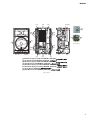
remove the screws mentioned in the table below. (Fig.2)
b) INPUT/MIX/SW/AC INLET circuit boards:
Remove the knobs and screws, and then disconnect the
connectors mentioned in the table below. (Fig.2, Photo.1)
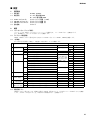
AMP/INPUT/MIX/SW/AC INLET シート
( 所要時間:7 分 )
5-1.
5-2.
ア ンプ Ass’y を外 し ます。 (1 項参照 )
各シー ト は下記の手順で外 し ます。
a) AMP シー ト : 下表の各 コ ネ ク タ ーの接続を外 し て
か ら 、 ネジ を外 し ます。 ( 図 2)
b) INPUT/MIX/SW/AC INLET シー ト :
ノ ブお よ び下表のネジ を外 し てか ら 、 各 コ ネ ク タ ーの
接続を外 し ます。 ( 図 2、 写真 1)
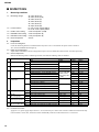
PCB Name
REF No.
Description
QTY
AMP
Circuit Board
CN201/CN202/CN203/
CN204/CN205
Connector
One for each
(total 5)
A24
Bind Head Sems Screw 3x12 MFZN2BL (AAX64760) +バイ ン ド セムス小ネジ
13
A1
5
CN101
Bind Head Screw 3x6 MFZN2BL (AAX64740) +バイ ン ド 小ネジ
Connector
A16
Phone Jack Nut (--) ホーン ジ ャ ッ ク ナ ッ ト
1
A14
Bonding Tapping Screw-B 3x8 MFZN2BL (AAX64840) ボンデ ィ ング B タ イ ト
Connector
INPUT
Circuit Board
MIX
Circuit Board
CN102/CN103/CN104/
CN105
A1
SW
Circuit Board
CN106/CN107
Bind Head Screw 3x6 MFZN2BL (AAX64740) +バイ ン ド 小ネジ
Connector
1
4
One for each
(total 4)
4
One for each
(total 2)
CN106
Bind Head Screw 3x6 MFZN2BL (AAX64740) +バイ ン ド 小ネジ
Connector
2
AC INLET
Circuit Board
A1
Bind Head Screw 3x6 MFZN2BL (AAX64740) +バイ ン ド 小ネジ
2
A8
Bind Head Tapping Screw-B 4x8 MFZN2BL (AAX64730) +バイ ン ド B タ イ ト
1
A1
1
A13
2
Bind Head Screw 3x10 MFZN2BL (AAX64750) +バイ ン ド 小ネジ
※ There is a GND wire connected the MIX and INPUT circuit boards with solder. When removing the MIX or INPUT circuit
boards, remove both of them simultaneously and remove solder on GND terminals. The MIX and INPUT circuit boards can
then be separeted.
※ MIX シー ト と INPUT シー ト にはアース線がはんだ付け さ れています。 MIX シー ト または INPUT シー ト を取 り 外す と きは両方を同時に
外 し 、 アース端子に付いてい るはんだ を外 し ます。
6.
Power Transformer
6-1.
6-2.
Remove the amplifier assembly. (See procedure 1.)
Remove the four (4) screws marked [A18]. The power
transformer can then be removed. (Fig.2)
6.
(Time required: about 7 minutes)
8
電源トランス
(所要時間:7 分)
6-1.
6-2.
ア ンプ Ass’y を外 し ます。 ( 1 項参照)
[A18] の 4 本を外 し 、電源 ト ラ ン ス を外 し ます。(図 2 )